Roof challenge
ROOF DESIGN
AIM
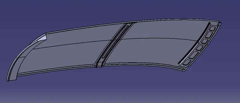
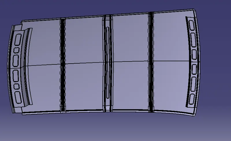
Create a car roof on the given Class A with the help of given master section and the appropriate design consideration. Check section modulus of front roof rail, rear roof rail, bow roof rails, and center roof rail.
ROOF
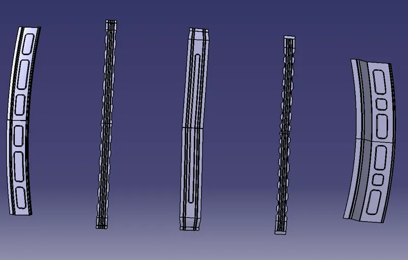
Roof is the component of a car which sits at the top of the car or above the passenger compartment. It protects the passenger from the sun, wind, ran, dust and other elements. Roof is consist of four roof rails ( Front roof rail, rear roof rail, bow roof rails, center roof rail ). It is connected with the front roof rail and rear roof rail. Bow roof rails and center roof rail is attached by the mastics.
FRONT ROOF RAIL
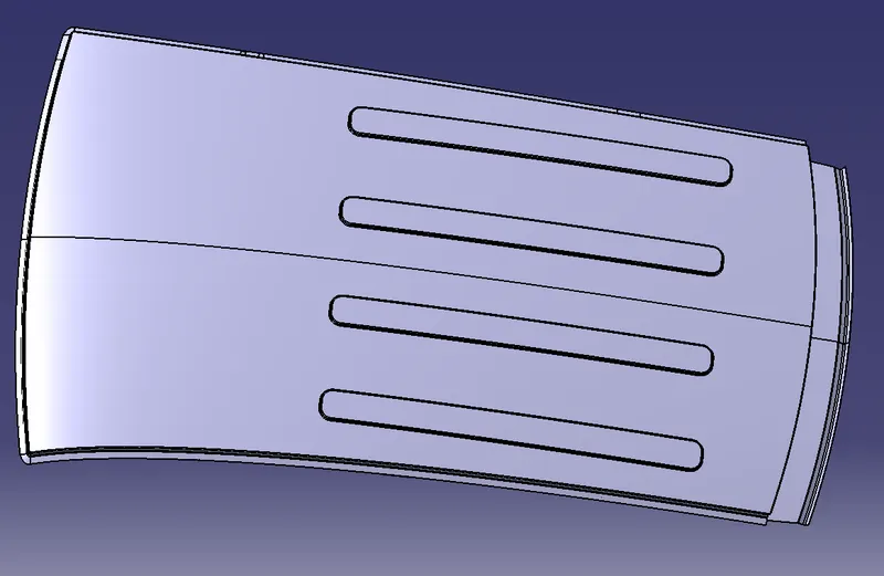
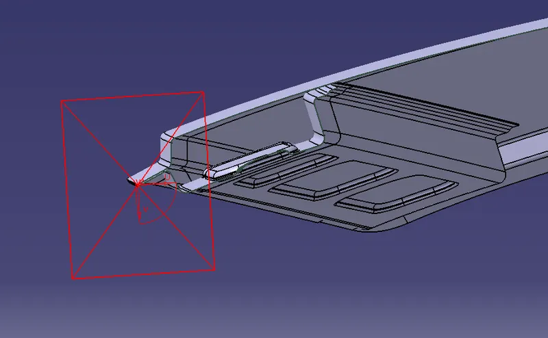
Front roof rail is created according to the mastersection given and with the design considerations. It is attached to the roof. It is created to give the support to the roof. Embosses are created on the front roof rail to give strenght to it.
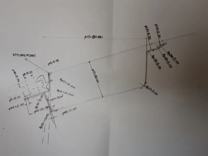
Master section of front roof rail
REAR ROOF RAIL
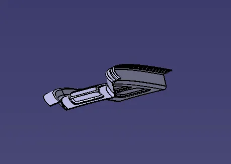
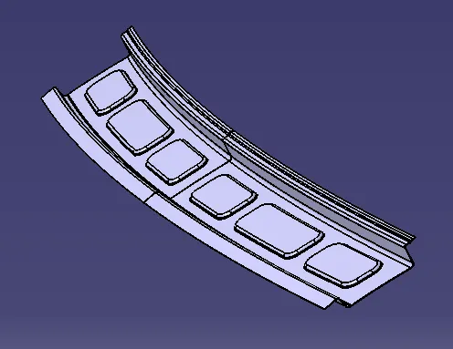
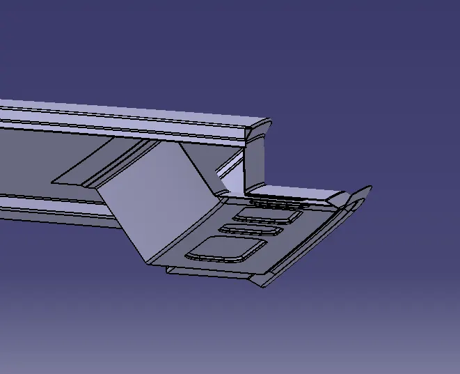
Rear roof rail is the component which is attached to the roof and as well as tail gate. There should be more gap between the rear roof rail and upper roof compare to the front roof rail because there should be a gap for tail gate to rotate. Rear roof rail is created according to the mastersection given and with the design considerations. we create the embosses on rear roof to give strenght to it.
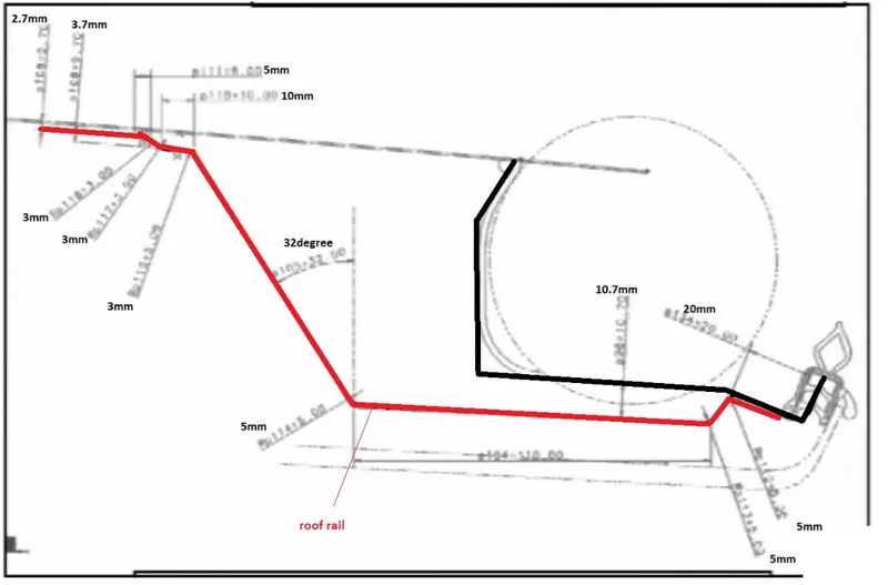
Master section of rear roof rail
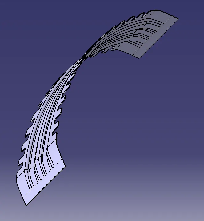
BOW ROOF RAILS
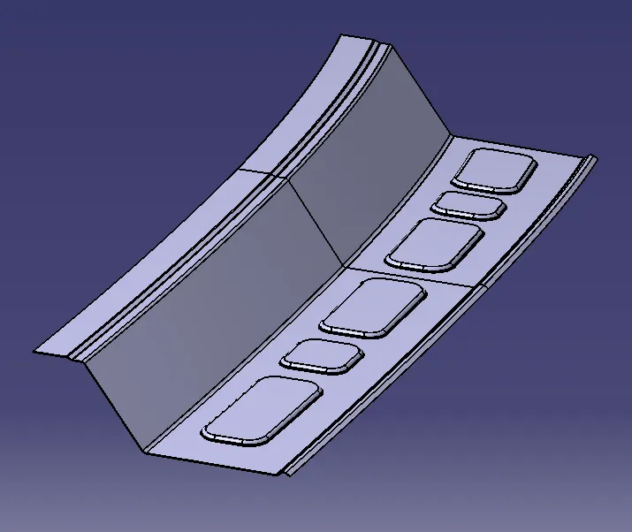
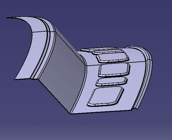
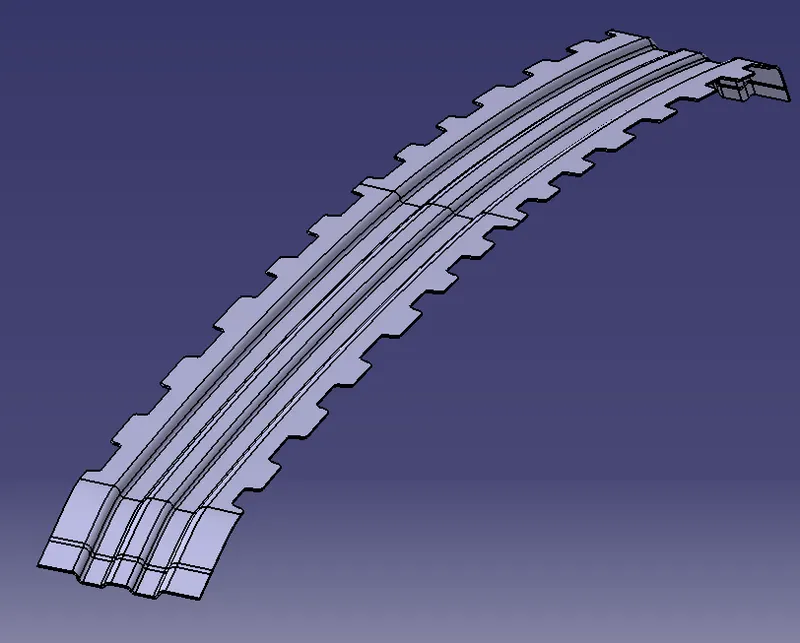
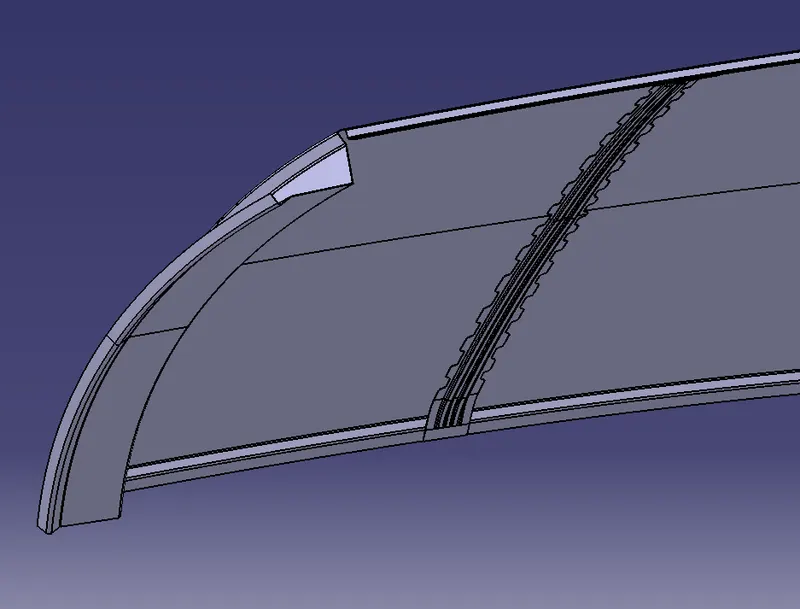
Reinforcement are created on the bow roof rails for increasing the strenght of the bow roof. There should be minimum 4mm gap between the bow roof rails and roof upper part so that the mastics that we have provided should be jion with the roof upper part and bow roofs. Bow roof rails is created according to the mastersection given and with the design considerations.
BOW ROOF RAIL 1
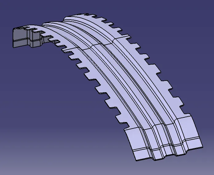
BOW ROOF RAIL 2
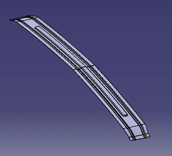
CENTER ROOF RAIL
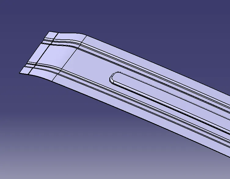
Similar to other roof rail design we have to create these by the consideration. For the center roof rail spot welds are not applied for joining the rails to roof, instead mastic sealants are introduced at both the end since center roof rail and bow roof rails are fully positioned under the styling surface of the roof. Embosses are created to increase the strenght of the component and it also reduces the weight of the component.
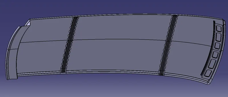
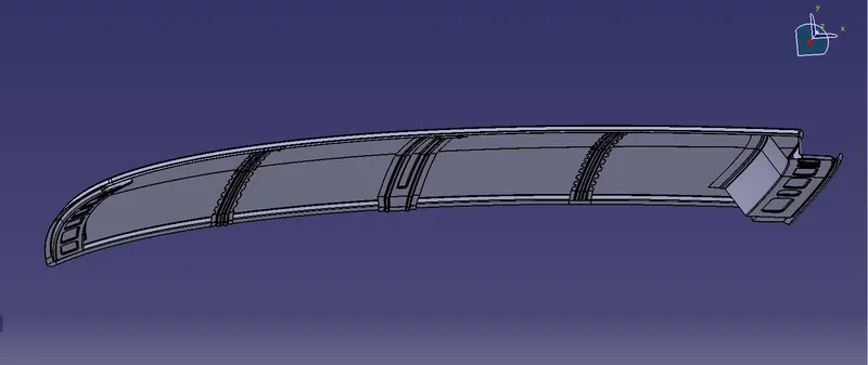
COMPLETE ROOF DESIGN
HEAT DISTORTION CRETERIA
Heat distortion study will pay an important role in sheetmetal. Heat distortion tempereture is the temperature limit above which the material cannot be used for structural applications. The study is used to predict heat distrotion temperature at where the material starts to soften when exposed to a fixed load at elevated temperature. In order to avoid the damage on roof, based on heat distrosion temperature, these study will pridict the bow rof position on the roof to strenght the roof.
Formula,
W = (1.73 x 10^-3 x L ) + [ 1.85 x 10^-8 x R^2/t ] + (1.10 x 10^-3 x l - 2.68 )
Condition OK<2.7<NG
Where ,
L - Roof lenght in X direction (mm) [Roof dimension in O-Y]
R - Roof curvature [R=2(Rx X Ry ) / (Rx + Ry )
Rx - X curvature
Ry - Y curvature
t - Roof plate thickness (mm).
l - Bow roof span (mm
|
ROOF |
L(length) mm |
Rx (mm) |
Ry (mm) |
Thickness (t) mm |
Width (l) |
W |
Status |
|
FR & BW1 |
2045.02 |
2500.006 | 5739.434 | 0.75 | 392.378 | 1.587 | OK |
| BW1 & CR | 2045.02 | 6160.943 | 4980.8 | 0.75 | 384.141 | 2.027 | OK |
| CR & BW2 | 2045.02 | 10340.143 | 4024.13 | 0.75 | 422.954 | 2.154 | OK |
| BW2 & RR | 2045.02 | 14932.017 | 3227.395 | 0.75 | 365.521 | 1.961 | OK |
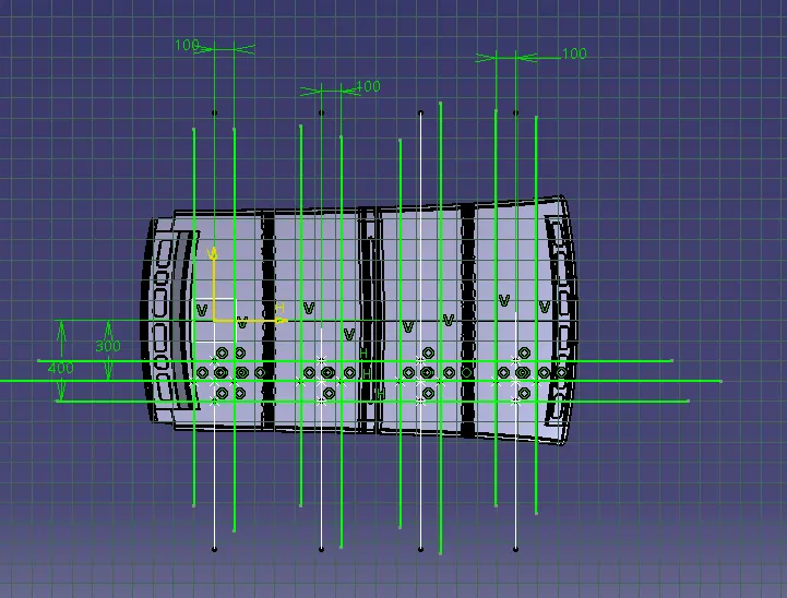
SNOWED CRITERIA
Snow load Prediction formula
Qr = [Iy x t2] / [α x s x [(Rx + Ry)/2]2 x 10-8]
Where,
α = My x Lx2 x 10-12 ,
My = Y(Ly-Y)
Judgement condition = Qr ≥ 3.1
250 ≤ s ≤ 380
t = Roof plate thickness [mm]
Ly = Distance between the front and rear roof Rails on the Vehicle along with 0Y[mm]
Length of Roof panel with the center point between Roof rail Front /Rear as the reference point of the front and the rear.
Lx = Distance between the Left and Right end of the roof on the Roof BOW [mm]
Width of the roof panel exposed on the surface.
Y = Distance from Front Roof Rail to Roof BOW[mm]
s = Distance for which Roof BOW bears divided load [mm]
s = L1/L2 + L2/2
Iy = Geometrical moment of inertia of Roof BOW (Y cross-section )[mm4]
Rx = Lateral direction curvature radius of roof panel Y cross-section on Roof BOW [mm]
Roof panel curvature Radius of the Length Lx in Front view
Ry = Longitudinal Direction curvature radius of the Roof panel X cross-section on Roof BOW [mm]
Roof panel X curvature radius of length s in Side view
BOW ROOF RAIL 1
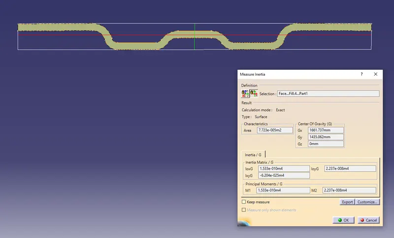
CENTRE ROOF RAIL
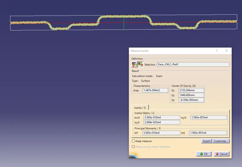
BOW ROOF RAIL 2
| ROOF | Y | LY | LX | S | Thickness | Rx | Ry | ALFA (α) | Iy | Qr | Status |
| FR&BW1 | 396.47 | 2000.33 | 1105.69 | 236.85 | 0.75 | 978.173 | 5528.25 | 0.777 | 153.3 | 11.33 | OK |
| BW1&CR | 384.16 | 2000.33 | 1068.56 | 255.44 | 0.75 | 3130.49 | 4803.71 | 0.708 | 558.5 | 28.25 | OK |
| CR&BW2 | 423.23 | 2000.33 | 1048.22 | 274.63 | 0.75 | 7811 | 4135.05 | 0.733 | 127.9 | 2.56 | NG |
| BW2&RR | 365 | 2000.33 | 0 | 0 | 0.75 | 1100.742 | 3416.34 | 0 | 0 | 0 | NG |
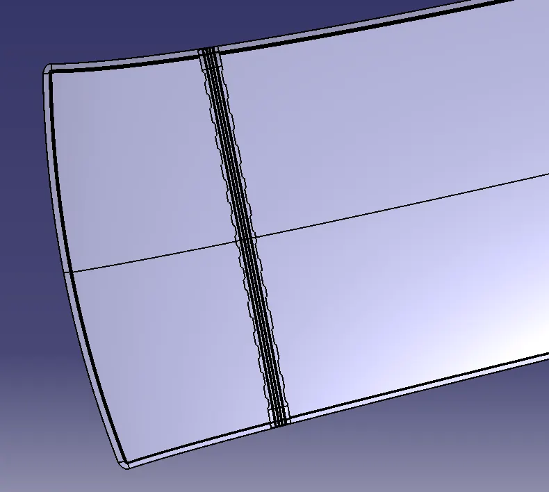
Embosses on the roof
Bow roof rail 1 and centre roof rail both are passed from thr snowed criteria that means they are having a good strenght and a good curvature that can carry the load but embosses are created on the roof because bow roof rail 2 has not passed the snowed criteria. Hence for increasing the strenght of the roof we create it. The emboss will help to give the good strenght to the roof to carry the load.