Roof challenge
Roof Design
Aim: To Design Roof, Front roof rail, Rear Roof Rail, Bow Roofs, and reinforcement roof center by following the Master section with the design parameter for the given class A surface
Introduction: An automobile roof or car top is the portion of an automobile that sits above the passenger compartment, protecting the vehicle occupants from sun, wind, rain, and other external elements.
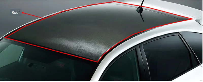
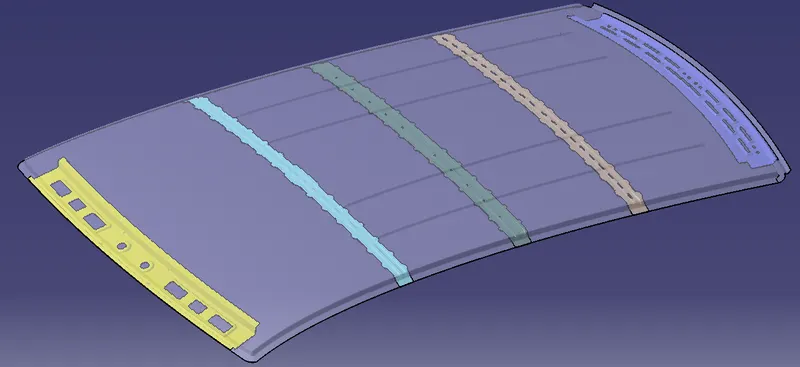
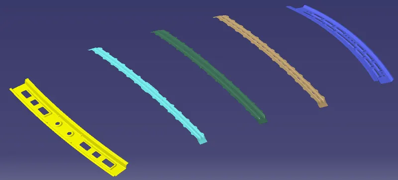
Roof is consisting of the following parts shown in the fig 0.1A
1. Roof: An automobile roof or car top is the portion of an automobile that sits above the passenger compartment, protecting the vehicle occupants from sun, wind, rain, and other external elements.
2. Front Roof Rail: Front roof rail is the additional commodity which acts as reinforcement also it has certain features in it which will be supporting bracket maplamp and room lamp
3. Rear Roof Rail: Rear roof rail is mainly supporting the roof. And also the back door hinges in order to make opening and closing.
4. Reinforcement center: Is the main supporting member of the roof where it helps to absorb energy at the time of side crash. Also it acts as a bow roof for small cars.
5. Bow Roofs: This is the roof supporting rails, which are provides additional stiffness, designed based on Heat Distortion Criteria and Snow load Condition,
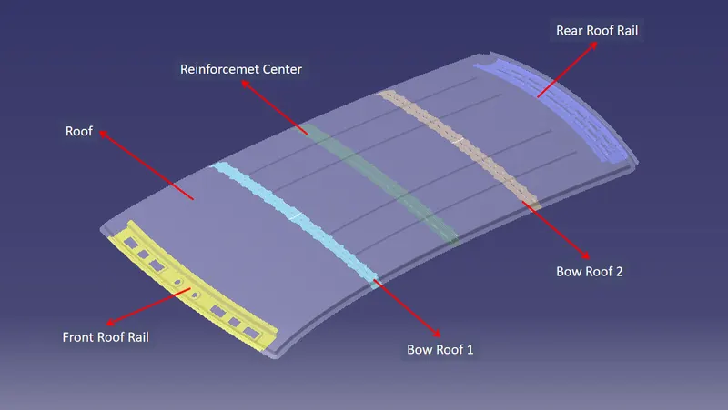
Fig.0.1A: Roof Parts
Design Procedure:
1. Import the file: File > open > browse file and select the given file (Product name.igs) shown in the fig. 1A.
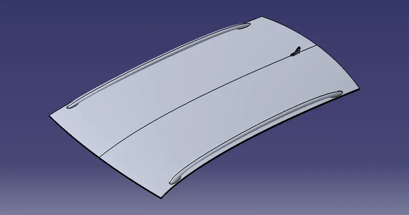
Fig.1A: Imported File
1. Roof design:
Given surface is A class and we have to Design Roof using the given class A with the help of the Given master section shown in the fig 1B.
Master section is developed based on the previous car model and Head Roof clearance 85mm, There are two master sections on it for front and other one is for rear side.
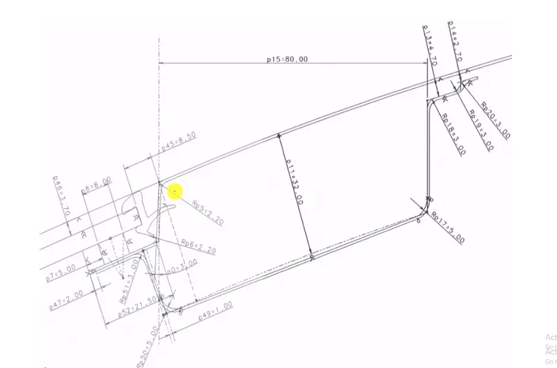
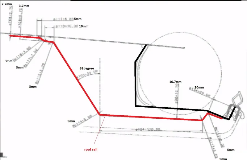
Fig.1B: Master section
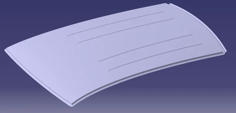
From the class A roof is developed by using mastersection. shown in the fig 1C.
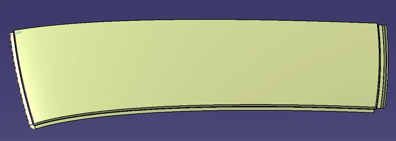
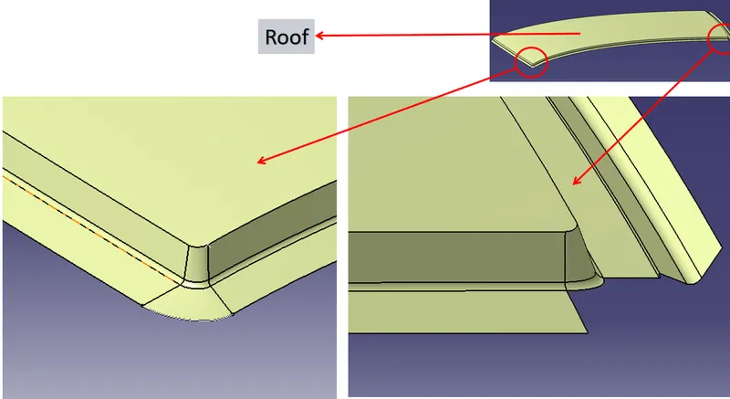
Fig.1C: Roof
Using a symmetry option to reflect surfaces and join,
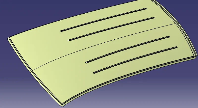
In part design, use a thick surface option to make sheet, here 0.75mm is the thickness of the roof In the fig.1.C
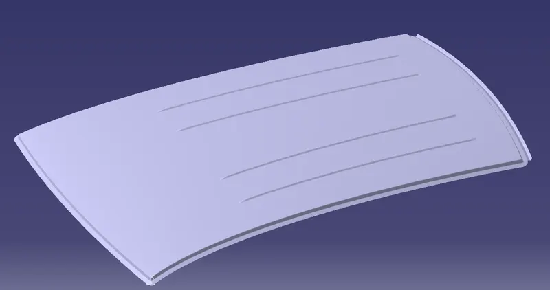
Fig.1c: roof
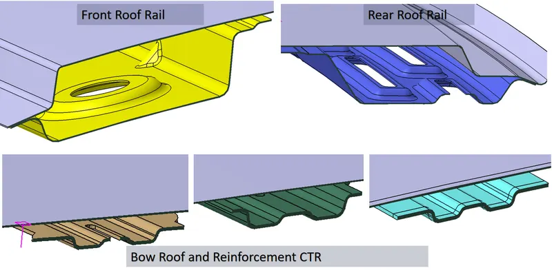
2. Front and Rear Roof rail Design: We are using the same master section which is used on the roof. This master section is developed based on Visibility criteria and head roof clearance.
From the class A roof is developed by using mastersection. shown in the fig 2.1. for front and rear roof rails
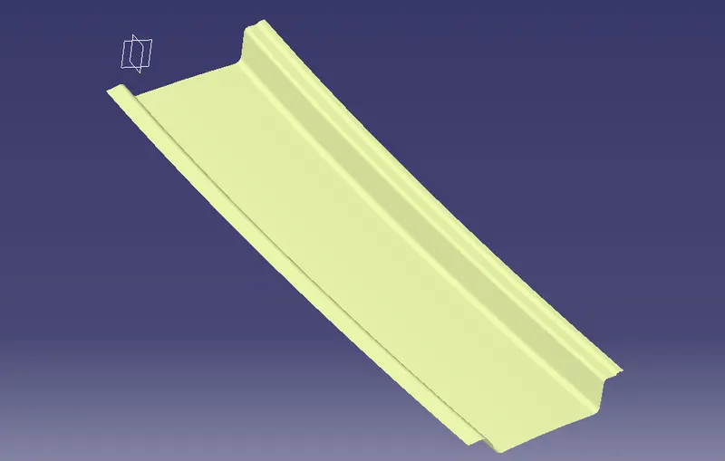
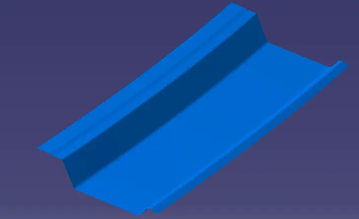
Fig.2.1: Front and Rear Roof rail
In order to make more stiffer and better moment of inertia emboss are created for both rails. shown in the fig 2.2. for front and rear roof rails
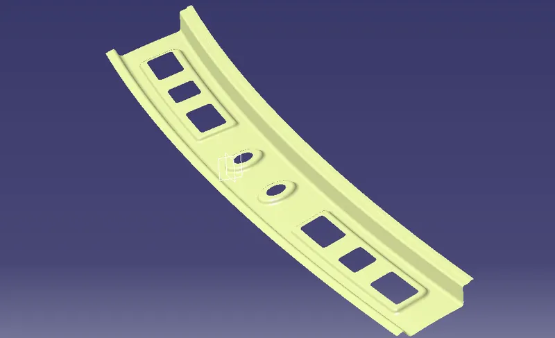
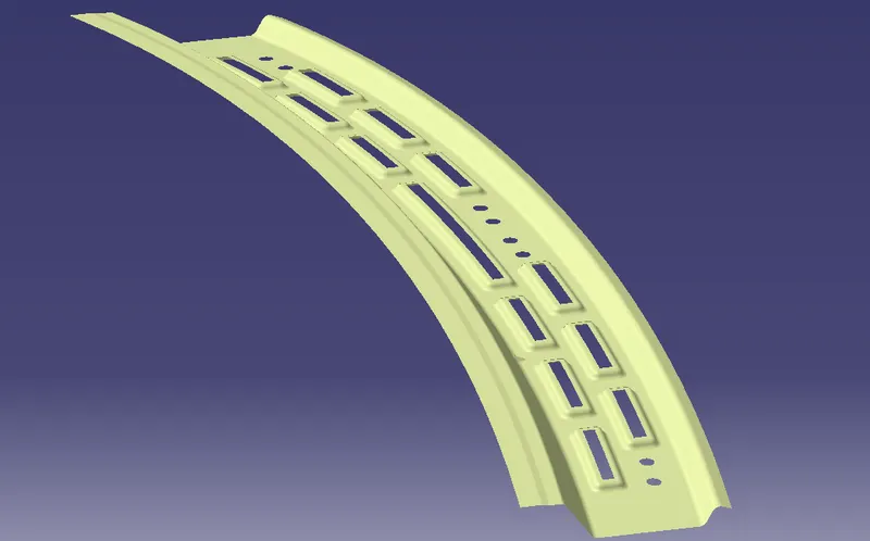
Fig.2.2: Front and Rear Roof rail
In part design, use a thick surface option to make sheet, here 0.75mm is the thickness show In the fig.2.3
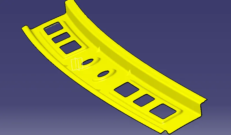
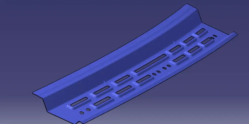
Fig.2.3: Front and Rear Roof rails
Similarly Design bow roof rails and Reinforcement center Shown in the fig. 3.1
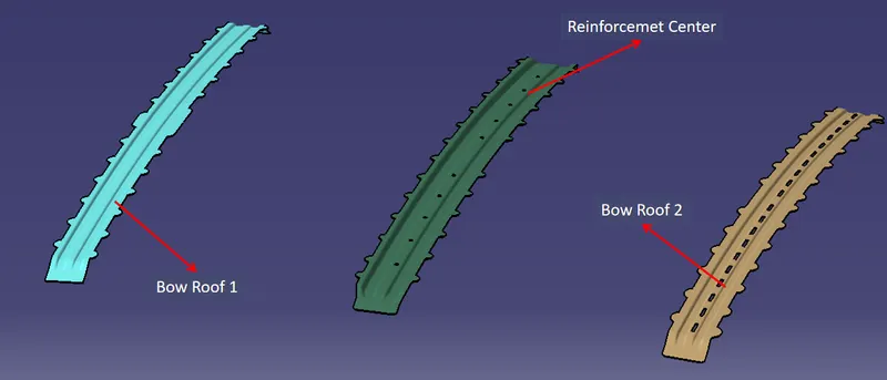
Fig.3.1: Bow roof rails and Reinforcement center
4. Bow Roof prediction Formula
A. Heat Distortion Criteria
W = [1.73 x 10^(-3) x L] + [1.85 x 10^(-8) x (R^2)/t] + [ 1.10x10^(-3) x l] - 2.68
Judgement Condition : OK< 2.7> 3.1
Where
L = Roof Length in X-Direction[mm](Roof dimension in 0-Y)
R = Roof curvature
R = 2(Rx*Ry)/(Rx+Ry)
Rx = X curvature
Ry = Y curvature
t = Roof plate thickness [mm]
l = Bow Roof Span [mm]
From the Model we have all the values shown in the fig 4.A.
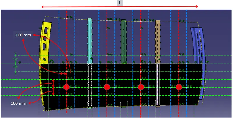
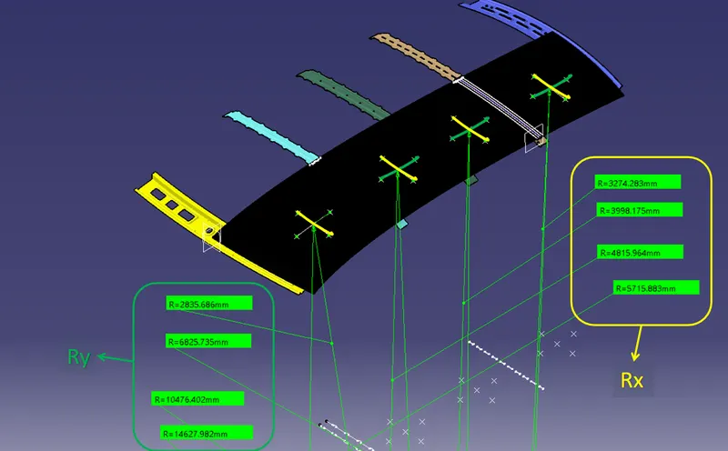
Fig.4.A: Heat Distortion Criteria
Calculations are done and tabulated in the table 1.1
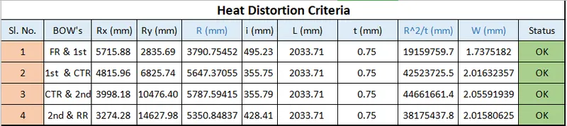
Table.1.1: Calculations
B. Snow load Prediction formula
Qr = [Iy x t2] / [α x s x [(Rx + Ry)/2]2 x 10-8]
Where
α = My x Lx2 x 10-12 , My = Y(Ly-Y)
Judgement condition = Qr ≥ 3.1
250 ≤ s ≤ 380
t = Roof plate thickness [mm]
Ly = Distance between the front and rear roof Rails on the Vehicle along with 0Y[mm] Length of Roof panel with the center point between Roof rail Front /Rear as the reference point of the front and the rear.
Lx = Distance between the Left and Right end of the roof on the Roof BOW [mm] Width of the roof panel exposed on the surface.
Y = Distance front Front Roof Rail to Roof BOW[mm]
s = Distance for which Roof BOW bears divided load [mm]
s = L1/2 + L2/2
Iy = Geometrical moment of inertia of Roof BOW (Y cross-section )[mm4]
Rx = Lateral direction curvature radius of roof panel Y cross-section on Roof BOW [mm] Roof panel curvature Radius of the Length Lx in Front view.
Ry = Longitudinal Direction curvature radius of the Roof panel X cross-section on Roof BOW [mm] Roof panel X curvature radius of length s in Side view.
From the Model we have all the values shown in the fig 4.B
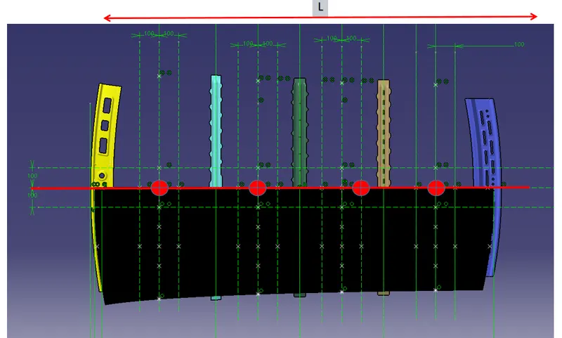
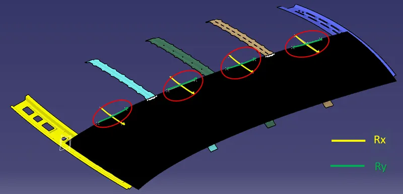
Fig.4.B: Snow load Prediction formula
for Geometrical moment of inertia we need section at each rail, and shown in the fig.
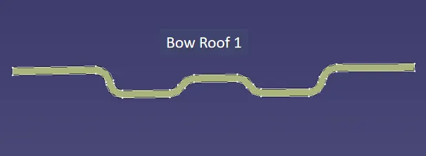
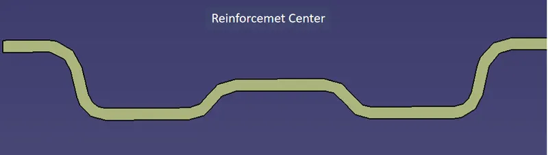
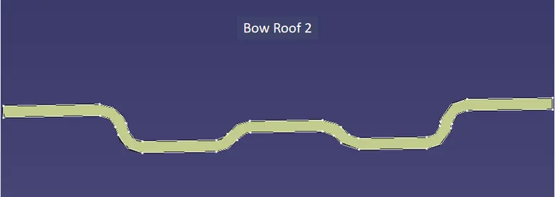
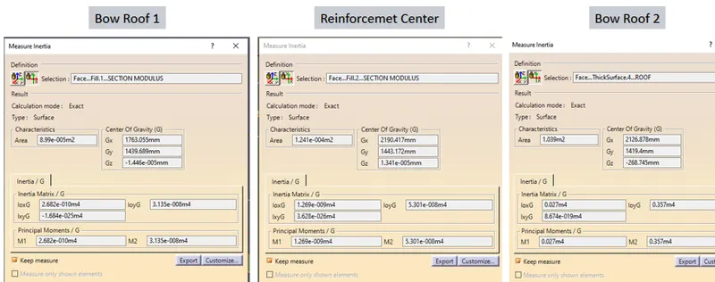
Calculations are done and tabulated in the table 2.1
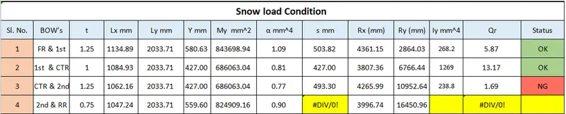
Table.2.1: Calculations
From the calculations we found bow roof 2 NG, So we have to ask the styling team to modify the surface with curvature in y as 6952.64. If team is rejected to do modification on curvature
Also we can provide emboss in the roof show in the fig.4.C. this embosses are locally increased the strength of roof.
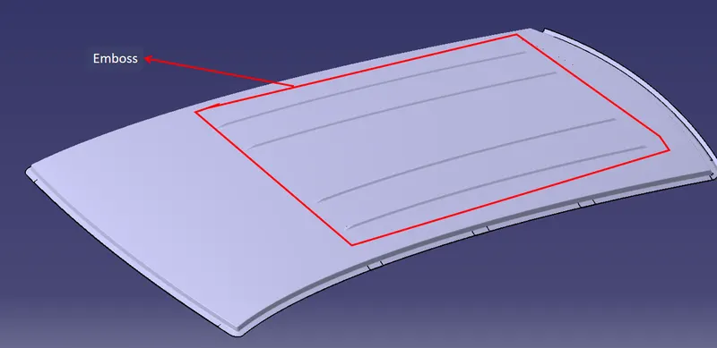
Fig4.C: Roof Emboss
5. Section Modulus calculation
Introduction: Section properties involve the mathematical properties of structural shapes. They are of great use in structural analysis and design. Note that these properties have nothing to do with the strength of the material, but are only based on the shape of the section. Those properties are
centre of area (or centroid)
second moment of area or moment of inertia (I)
section modulus (S)
radius of gyration (r)
Though generally section modulus is calculated for the extreme tensile or compressive fibres in a bending beam, often compression is the most critical case due to onset of flexural torsional buckling. Generally tensile extreme fibres have a higher allowable stress or capacity than compressive fibres.
centre of area (or centroid): The centroid of a section is important in structural design and is like the centre of gravity of the shape. Many other simple shapes are symmetrical about the x-x and y-y axes and the centroid can easily be seen
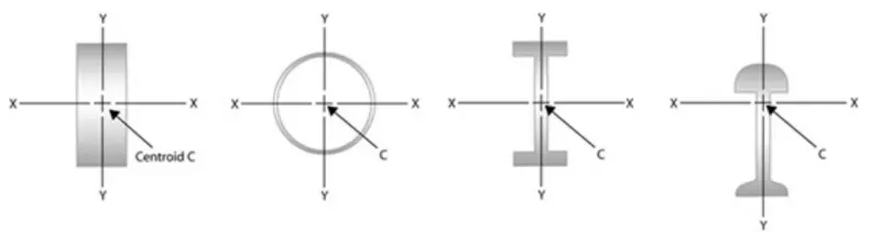
second moment of area or moment of inertia (I): The second moment of area is a geometrical property of an area which reflects how its points are distributed with regard to an arbitrary axis. The second moment of area is typically denoted with either an I
The second moment of area is also known as the moment of inertia of a shape. It is directly related to the area of material in the cross-section and the displacement of that area from the centroid. Once the centroid is located, the more important structural properties of the shape can be calculated. The axis that determines the centroid is also known as the neutral axis (N/A). The second moment of area is a measure of the 'efficiency' of a shape to resist bending caused by loading. A beam tends to change its shape when loaded. The second moment of area is a measure of a shape's resistance to change.
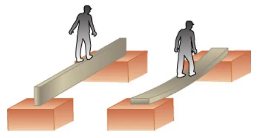
Certain shapes are better than others at resisting bending as demonstrated in the diagram. Clearly, the orientation of the shape also influences bending.
Calculating the moment of inertia (I):
For simple shapes such as squares, rectangles and circles, simple formulas have been worked out and the values must be calculated for each case.
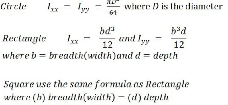
A standard method of denoting moment of inertia is to write the value mm4.
section modulus (S): The section modulus of the cross-sectional shape is of significant importance in designing beams. It is a direct measure of the strength of the beam. A beam that has a larger section modulus than another will be stronger and capable of supporting greater loads.
section modulus is denoted by S. To calculate S, the distance (y) to the extreme fibres from the centroid (or neutral axis) must be found as that is where the maximum stress could cause failure.
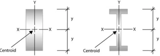
Calculating the section modulus by S = I/y
where I = moment of inertia, y = distance from centroid to top.
For symmetrical sections the value of S is the same above or below the centroid. For asymmetrical sections, two values are found: S max and S min.
radius of gyration (r): This is another property of a section and is also a function of the second moment of area. Put in general terms, the radius of gyration can be considered to be an indication of the stiffness of a section based on the shape of the cross-section when used as a compression member.
The diagram indicates that this member will bend in the thinnest plane.
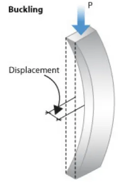
The radius of gyration is used to compare how various structural shapes will behave under compression along an axis. It is used to predict buckling in a compression member or beam.
The formula for the radius of gyration r is:
`r = sqrt(I/A)` in mm
where I = second moment of area
A = area of material in the cross section
Procedure:
1. Create Intersection: Create intersection for outer and inner panel by using Intersection tool
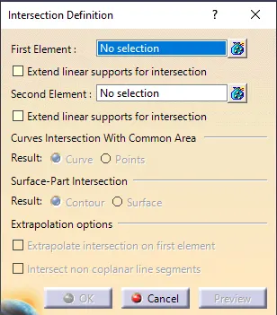
Where the first element is the element you want to cut and the second element is the cutting element or plane. in the fig 5.1 shown section for roof
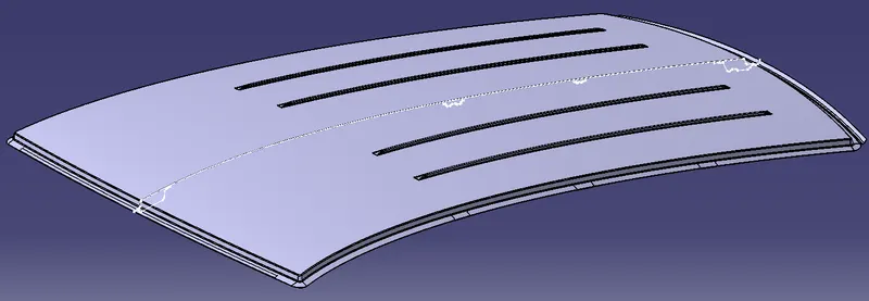
Fig5.1: Intersection
Boundary for Cross sectional area: In order to calculate Moment of Inertia, we have to create 2D cross section plane, for creating
a. select outer most intersection line of outer panel and inner most intersection line of inner panel.
b. Fill in gaps by using Spline and make sure that there is no any gap or discontinuity.
c. Join all the lines and create a surface by using Fill. shown in the fig.
3. Calculating the section modulus: To calculate section modulus by S = I/y. where I = moment of inertia, y = distance from centroid to top.
We need I = moment of inertia, y = distance from centroid to top
Moment of Inertia: by using measure inertia tools we can find the Moment of Inertia of any shape of 2D geometry.
1. Front roof rail and Roof:
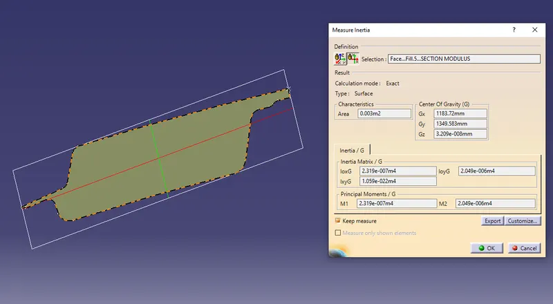
From the fig. we have Min and Max of I which is M1 and M2.
M1 = 2.319 X 10^5 mm^4
M2 = 2.049 X 10^6 mm^4
y = distance between the neutral axis and the extreme end of the object = 58.553mm
So
S1 = I/y
= 2.319 X 10^5 mm^4 / 58.553mm
S1 = 3960.514 mm^3
S2 = 2.049 X 10^6 mm^4/ 58.553mm
S2 = 34993.93 mm^3
2.Rear Roof Rail and Roof:
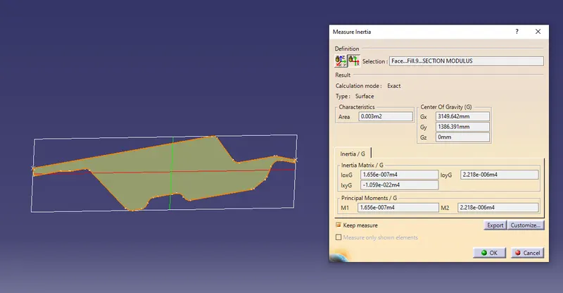
From the fig. we have Min and Max of I which is M1 and M2.
M1 = 1.656 X 10^5 mm^4
M2 = 2.218 X 10^6 mm^4
y = distance between the neutral axis and the extreme end of the object = 58.553mm
So
S1 = I/y
= 1.656 X 10^5 mm^4 / 71.836 mm
S1 = 2305.25 mm^3
S2 = 2.218 X 10^6 mm^4/ 71.836 mm
S2 = 30875.88 mm^3
3. Bow Roof 1 and 2 and Roof:
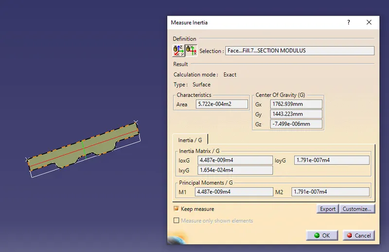
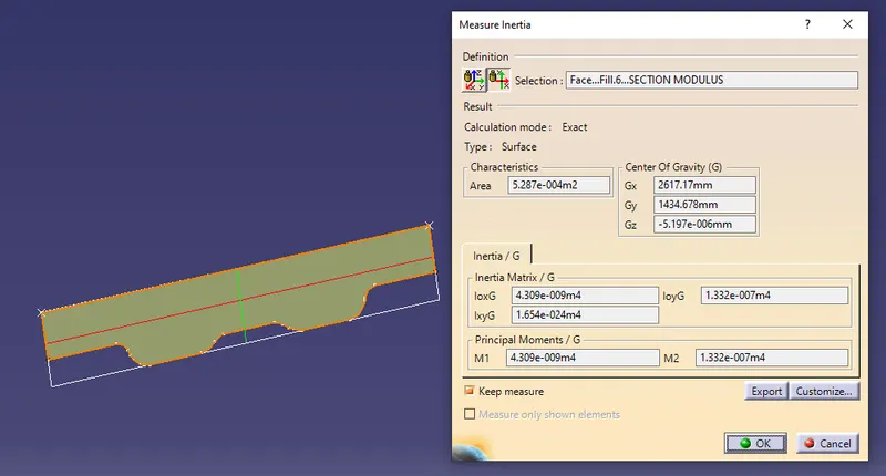
From the fig. we have Min and Max of I which is M1 and M2.
for bow roof 1
MB1 = 4487 mm^4
MB2 = 1.79100 X 10^5 mm^4
y = distance between the neutral axis and the extreme end of the object = 29.66 mm
So
S1 = I/y
= 4487 mm^4 / 33.14 mm
S1 = 135.39 mm^3
S2 = 1.791 X 10^5 mm^4/ 33.14 mm
S2 = 179066.86 mm^3
for bow roof 2
MB1 = 4309 mm^4
MB2 = 1.332 X 10^5 mm^4
y = distance between the neutral axis and the extreme end of the object = 29.66
So
S1 = I/y
= 4309 mm^4 / 29.66 mm
S1 = 145.2 mm^3
S2 = 1.332 X 10^5 mm^4/ 29.66 mm
S2 = 4490 mm^3
4 .Reinforcement Center and Roof:
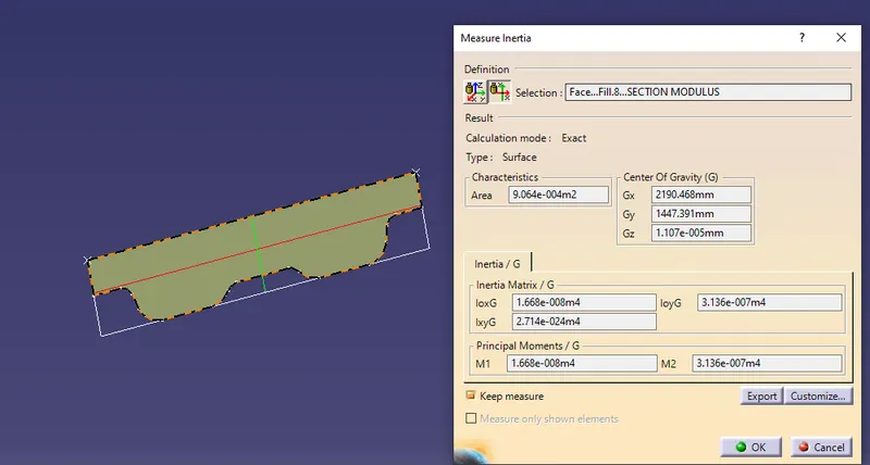
From the fig. we have Min and Max of I which is M1 and M2.
M1 = 16680 mm^4
M2 = 313600 mm^4
y = distance between the neutral axis and the extreme end of the object = 35.05mm
So
S1 = I/y
= 16680 mm^4 / 35.05 mm
S1 = 475.89 mm^3
S2 = 313600 mm^4/ 35.05 mm
S2 = 8947.21 mm^3
1. As we knew larger section modulus than another will be stronger and capable of supporting greater loads. so from the above we can see more section modulus so by increasing area we can get more stronger and capable of supporting greater loads
2. So by changing section area, we can change the strength of hood, so depending on the feedback from the CAE team we can change strength.
6 . Draft Analysis: Draft analysis is a method of checking the draft angle on various faces of a part with a particular direction. it should be more than 7 deg.
In the fig 6.1A show the draft analysis for Roof, Front Roof Rail, Rear Roof Rail, Bow Roofs and Reinforcement Center.
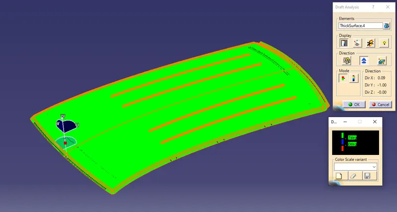
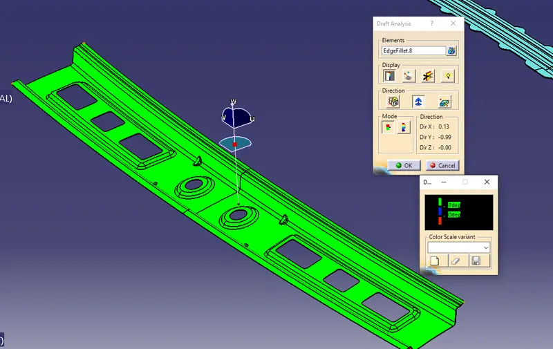
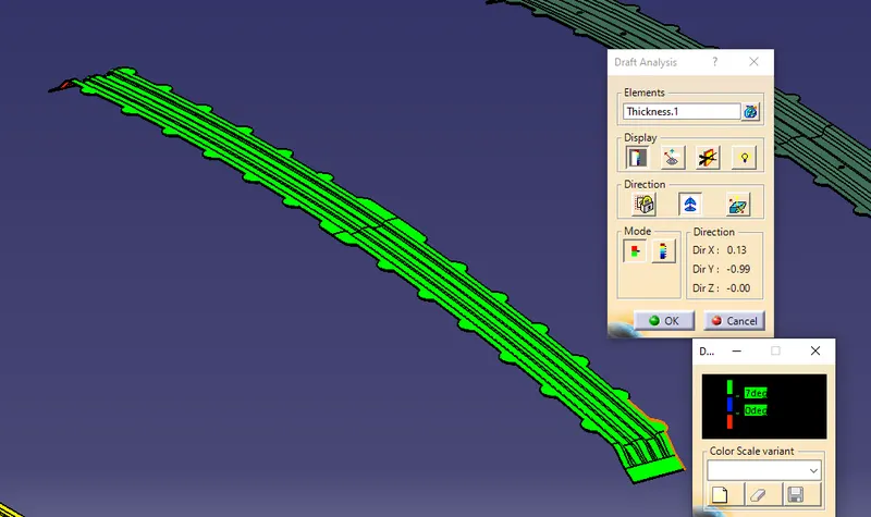
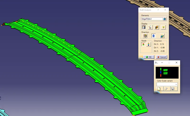
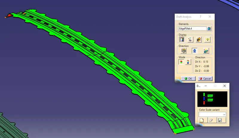
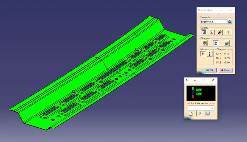
Fig.6.1A: Draft analysis
Results: The Design of Roof, Front roof rail, Rear Roof Rail, Bow Roofs, and reinforcement roof center by following the Master section with the design parameter for the given class A surface is done and the final model is shown in the fig. below.