Roof challenge
Aim
To design the roof to following the given master section
Introduction
Roof of an automobile sits above the passenger compartment. Roof houses the vehicle as a shielding part, which safeguards the occupants from sunlight, heat, rain, wind, dust and other external elements. In case of convertibles, it is called the hood.
In the past roof was introduced as cover for passenger compartment but later on, it was also used as a luggage carrier, sunroof and in recent past years with the introduction of the solar paneled electric vehicle got a major boost in the automotive industry.
Roof has the following functions
- Protects from external damage
- Act as a safety gear when a roll-over accident occurs
- Luggage carrier
- Design of the roof also affects in giving aerodynamic shape to vehicle
- Sunroof
- Solar paneled roof in EV
Since the roof has numerous functions. Therefore, the roof has to be stronger enough to withstand the damage experienced by it while roll-over. For that, the roof should have good strength and stiffness. So, the roof is made with embosses and some reinforcements, such as
- Front roof rail
- Rear roof rail
- Center roof rail
- Bow roofs
They are bonded with the roof through the spot welding and mastic sealant.
While designing the roof, few criteria should be followed, they are visibility, headroom clearance, heat distortion, snow load, curvature study.
Ditch area is provided on all the four sides of the roof. Roof ditch areas are provided to mount roof to the main body of the car also to mount windshield glass for the front ditch area, and to mount tailgate to rear ditch area
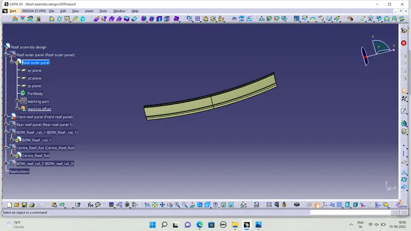
front roof rail
Front roof rail design should consider headroom clearance and visibility criteria and has mounting area for windshield glass. the thickness of front roof rail is 0.75 mm
Commands Used
Offset, fill, join, parallel, curve smooth, split, extract, sweep, multi section surface, edge fillet, plane, Sketch, project, extrapolate, symmetry, thicksurface, etc.
Rear roof rail
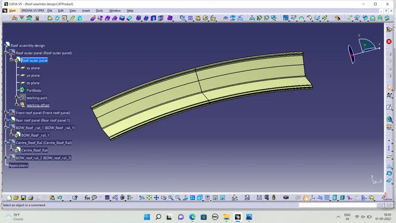
Rear roof rail is similar to the front roof rail. Rear headroom and rear visibility criteria are considered and also tailgate will be mounted on the rear roof rail so tailgate conditions have to be considered while designing the rear roof rail. the rear roof rail thickness also same from front roof rail 0.75mm
Commands Used
same commeds used to create or design rear roof rail also
Center roof rail
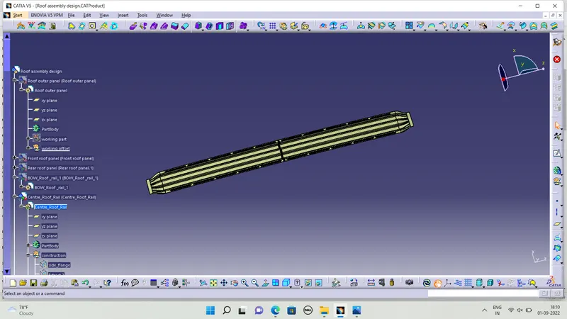
Center roof rail is a reinforcement support for the roof and it has the bracket for used for cabin light mount and center roof rail is most important part of roof the thickness of Center roof rail is 1.3 mm
Bow roof rail
In this design i used to design two bow roof rail there is enough for seden cars thats why i design two bow roof and bow roof has been provided for additional strength especially against snow conditions and rollover situations. In this model, one bow roof has been provided between front roof rail and Centre roof rail and another bow roof has been provided between Centre roof rail and rear roof rail. But the number of bows on the roof is based on the size of the car like small cars do not require a bow because it increases the weight of the car as well as the other rails are enough to provide the support for the roof. But for large cars 3 or more bows are needed to support the roof
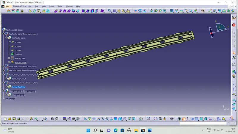
Commands Used:
Offset, plane, split, sweep, extract, boundary, curve smooth, join, edge fillet, sketch, extrude, line, multi section surface, thicksurface
Outer roof panel
outer roof is modelled using the styling surface as reference, then the ditch area and design a front flange rear flange and side flanges
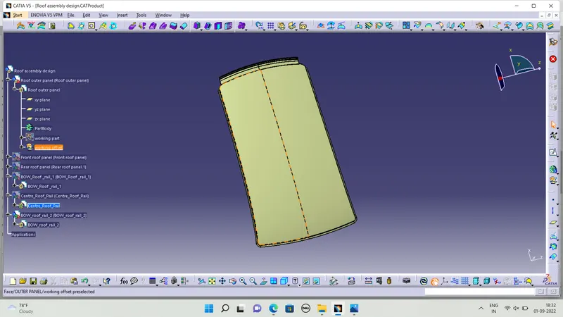
Position analysis
The position and moment of all the reinforcements are taken and checked, whether it satisfies the heat distortion test and snow load test. Necessary modifications should be taken if it fails to meet the requirements.
Heat distortion criteria
The roof is directly exposed to sunlight. The temperature changes with respect to time and season, it causes deformation in the roof. In order to prevent failure it should be designed in such a way else, it gets failure.
It is checked using the formula,
W = [1.73x10^-3 x L]+[1.85x10^-8 x (R^2)/t] +[ 1.10x10^-3 x l]-2.68
Where,
L = Roof Length in X-Direction [mm] (Roof dimension in 0-Y)
R = Roof curvature
R = 2(Rx*Ry) / (Rx+Ry)
Rx = X curvature
Ry = Y curvature
t = Roof plate thickness [mm]
l = Bow Roof Span [mm]
Judgement Condition: OK < 2.7 mm < NG
Table 1: Heat distortion criteria
| Rx(mm) | Ry(mm) | L(mm) | l(mm) | R(mm) | t(mm) | W | |
| FR-BOW-1 | 5771.602 | 2739.18 | 2027.244 | 380.89 | 3715.69 | 0.75 | 1.58667 |
| BOE-1- CRF | 4964.424 | 6135.75 | 2027.244 | 256.6 | 5488.23 | 0.75 | 1.85576 |
| CRF-BOW 2 | 3985.8 | 11069.37 | 2027.244 | 256.93 | 5846.33 | 0.75 | 1.96020 |
| BOW 2-RR | 3319.53 | 16169.63 | 2027.244 | 369.25 | 5508.69 | 0.75 | 1.98154 |
FR- Front roof rail
CR- Center roof rail
RR- Rear roof rail
Satisfying condition is W is lesser than 2.7
From the above table it is found that the value of W is lesser than 2.7, therefore the heat distortion condition is satisfied with this model.
Snow load condition
The roof is designed in such a way that the roof would bend slightly when the load is applied and regain its shape once the load is removed. Hereby the roof is tested to avoid plastic deformation.
It is checked using the formula,
Qr = [Iy x t2] / [α x s x [(Rx + Ry)/2]2 x 10-8]
Where, α = My x Lx2 x 10-12 , My = Y(Ly-Y)
Judgement condition : Qr ≥ 3.1
250 ≤ s ≤ 380
t = Roof plate thickness [mm]
Ly = Distance between the Front and rear roof Rails on the Vehicle along 0Y[mm]
· Length of Roof panel with the center point between Roof rail Front /Rear as the reference point of the front and the rear.
Lx= Distance between the Left and Right end of the roof on the Roof BOW [mm]
· Width of the roof panel exposed on the surface .
Y = Distance front Front Roof Rail to Roof BOW[mm]
s= Distance for which Roof BOW bears divided load [mm]
· s = L1/2 + L2/2
Iy = Geometrical moment of inertia of Roof BOW (Y cross section )[mm4]
Rx = Lateral direction curvature radius of roof panel Y cross section on Roof BOW [mm]
· Roof panel curvature Radius of the Length Lx in Front view
Ry = Longitudinal Direction curvature radius of the Roof panel X cross section on Roof BOW [mm]
Table 2: Snow load condition parameters
| Rx | Ry | Lx(mm) | Ly (mm) | Iy (mm4) | t (mm) | y (mm) | |
| FR-BOW1 | 5084.687 | 3929.765 | 1098.478 | 1947.06 | 1.10E+03 | 0.7 | 516.549 |
| BOW1- CR | 4446.932 | 8174.768 | 1065.706 | 1947.06 | 9.20E+03 | 0.7 | 449.581 |
| CR- BOW2 | 3848.156 | 13222.96 | 1046.817 | 1947.06 | 1.16E+03 | 0.7 | 449.821 |
| BOW2- RR | 1947.06 | 0.7 | 530.83 |
Table 3: Snow load condition (Qr) calculation
| My=Y(Ly-Y) | α= My*Lx^2*10^-12 | s=(L1/2)+(L2/2) | Qr |
| 738931.0927 | 0.891634097 | 483.065 | 6.176759 |
| 673239.9046 | 0.764618271 | 449.701 | 32.90416 |
| 673491.3435 | 0.738029211 | 490.3255 | 2.163353 |
| 751779.4942 | 0 | 265.415 |
To satisfy the snowload condition,The Qr value should be greater than or equal to 3.1
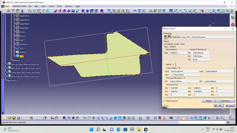
Moment of inertia of Front roof rail