Roof challenge
REPORT
AIM
For the Given Roof styling, create an ASSEMBLY by developing the essential flanges for the outer roof and creating the reinforcements.
Design a Roof with its components by following the master section of the front roof rail (at least 1 Front roof rail, two bow roofs, 1 centre roof rail and 1 rear roof rail) with all the design parameter Provide appropriate dimensions and check for Draft analysis.
Do a curvature study on the roof and perform calculations to determine the position of the Bow-roofs.
Bow–Roof Prediction Formula
W = [1.73 x 10^(-3) x L] + [1.85 x 10^(-8) x (R^2)/t] + [ 1.10x10^(-3) x l] - 2.68
Where,
L = Roof Length in X-Direction[mm](Roof dimension in 0-Y)
R = Roof curvature
R = 2(Rx*Ry)/(Rx+Ry)
Rx = X curvature
Ry = Y curvature
t = Roof plate thickness [mm]
l = Bow Roof Span [mm]
Judgment Condition
OK< 2.7
Snow Load Prediction Formula
Qr = [Iy x t2] / [α x s x [(Rx + Ry)/2]2 x 10-8]
Note: The Qr value given over here is correct. There was a typo error in the formula given in the video.
Where,
α = My x Lx2 x 10-12 , My = Y(Ly-Y)
t = Roof plate thickness [mm]
Ly = Distance between the front and rear roof Rails on the Vehicle along with 0Y[mm]
Length of Roof panel with the center point between Roof rail Front /Rear as the front and rear reference point.
Lx = Distance between the Left and Right end of the roof on the Roof BOW [mm]
The width of the roof panel is exposed on the surface.
Y = Distance front Front Roof Rail to Roof BOW[mm]
s = Distance for which Roof BOW bears divided load [mm]
s = L1/2 + L2/2
Iy = Geometrical moment of inertia of Roof BOW (Y cross-section )[mm4]
Rx = Lateral direction curvature radius of roof panel Y cross-section on Roof BOW [mm]
Roof panel curvature Radius of the Length Lx in Front view
Ry = Longitudinal Direction curvature radius of the Roof panel X cross-section on Roof BOW [mm]
Roof panel X curvature radius of length s in Side view
Judgment condition
Qr ≥ 3.1
250 ≤ s ≤ 380
INTRODUCTION
An automobile roof is the portion of an automobile that sits above the passenger compartment, protecting the vehicle occupants from sun, wind, rain, and other external elements. Under the styling surface that is seen from the outside, there are many other structures under the roof that contribute to its strength and stability. The number of such reinforcement structures/supports differ with respect to the size of the vehicle. They are primarily installed on flatter areas of the roof to enhance strength.
These are the Front Roof Rail, Rear Roof Rail, Centre Roof Rail, and Bow Roof Design which are given Mastics and spot-welded to roof flanges & ditch areas and improve NVH value by increasing the strength of the roof using mastic sealants.
An automobile roof or car top is the portion of an automobile that sits above the passenger compartment, protecting the vehicle occupants from sun, wind, rain, and other external elements. Because the earliest automobiles were designed in an era of carriages, early automobile roofs used similar materials and designs.
Variations
In later years, many variations on the automobile roof developed. These include:
Convertible roofs
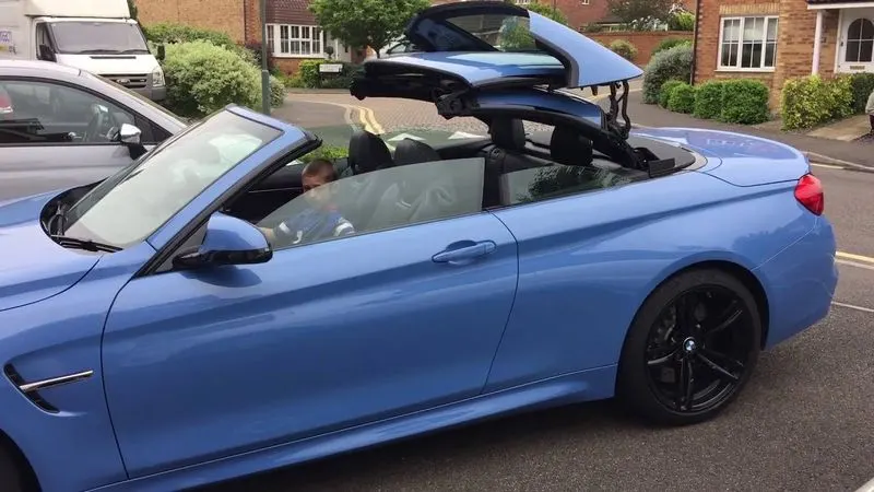
A convertible or cabriolet is a passenger car that can be driven with or without a roof in place. The methods of retracting and storing the roof vary among eras and manufacturers.
A convertible car's design allows an open-air driving experience, with the ability to provide a roof when required. A potential drawback of convertibles is their reduced structural rigidity (requiring significant engineering and modification to counteract the effects of removing a car's roof)
The majority of convertible roofs are of a folding construction framework with the actual top made from cloth or other fabric. Other types of convertible roofs include retractable hardtops (often constructed from metal or plastic) and detachable hardtops (where a metal or plastic roof is manually removed and often stored in the trunk).
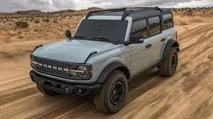
A hardtop is a rigid form of automobile roof, which for modern cars is typically constructed from metal. A hardtop roof can be either fixed (i.e. not removable), detachable for separate storing or retractable within the vehicle itself.
The pillarless hardtop (often referred to as simply "hardtop") is a body style of cars without a B-pillar, which are often styled to give the appearance of a convertible design.
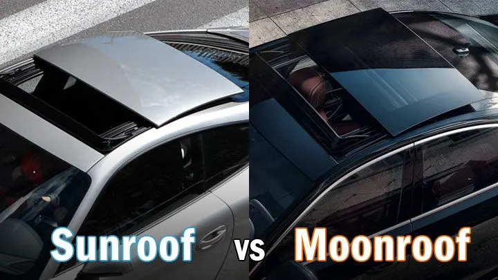
A sunroof is a movable panel that opens to uncover a window in an automobile roof, allowing light and fresh air to enter the passenger compartment. Sunroofs can be manually operated or motor driven, and are available in many shapes, sizes and styles. While the term "sunroof" is now used generically to describe any glass panel in the roof, the term "moonroof" was historically used to describe stationary glass panes rigidly mounted in the roof panel over the passenger compartment. A moonroof has a glass panel that is transparent and usually tinted. Previous terms include Sunshine Roof, Sliding Head and Sliding Roof.
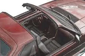
A T-top (UK: T-bar) is an automobile roof with a removable panel on each side of a rigid bar running from the center of one structural bar between pillars to the center of the next structural bar. The panels of a traditional T-top are usually made of auto grade safety glass.
Targa top, or targa for short, is a semi-convertible car body style with a removable roof section and a full width roll bar behind the seats. The term was first used on the 1966 Porsche 911 Targa, and it remains a registered trademark of Porsche AG.
The rear window is normally fixed, but on some targa models, it is a removable plastic foldable window, making it a convertible-type vehicle. Any piece of normally fixed metal or trim which rises up from one side, over the roof and down the other side is sometimes called a targa band, targa bar, or a wrap-over band.
Vinyl roof refers to a vinyl covering for an automobile's top.This covering was originally designed to give the appearance of a convertible to models with a fixed roof and eventually evolved into a styling statement in its own right. Vinyl roofs were most popular in the American market, and they are considered one of the period hallmarks of the 1970s domestic cars. Vinyl roofs were also popular on European- (especially UK-) and Japanese-built cars during the 1970s, and tended to be applied to sporting or luxury trim versions of standard saloon (sedan) models.
Functional requirements
- Protect the occupants from the environmental conditions
- To meet the roof crush regulations
- To contribute the structural performance of the body
- To maintain the dimensional accuracy of the body
Design consideration of roof:
- Visibility Criteria
- Head clearance
- Curvature study
- Heat distortion and snow load criteria
- Draft analysis.
- Safety parameters
Visibility Criteria
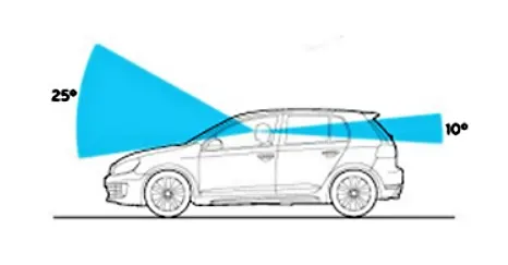
The visibility criteria of a driver is one of the most important factors when designing the roof. The roof should be designed such that it
does not hinder the visibility range of the driver. The ditch area of the roof is designed keeping this criterion in mind.
Head Clearance
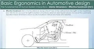
This factor is considered when designing the reinforcements of the roof. The reinforcements should be designed in a way that it
provides ample headroom clearance for the occupants in the car and does not collide with the head in case the car moves over a
bump It should not act as a hindrance to the driver’s rear visibility.
Curvature study
Bow–Roof Prediction Formula
W = [1.73 x 10^(-3) x L] + [1.85 x 10^(-8) x (R^2)/t] + [ 1.10x10^(-3) x l] - 2.68
Where,
L = Roof Length in X-Direction[mm](Roof dimension in 0-Y)
R = Roof curvature
R = 2(Rx*Ry)/(Rx+Ry)
Rx = X curvature
Ry = Y curvature
t = Roof plate thickness [mm]
l = Bow Roof Span [mm]
Judgment Condition
OK< 2.7
Snow Load Prediction Formula
Qr = [Iy x t2] / [α x s x [(Rx + Ry)/2]2 x 10-8]
Note: The Qr value given over here is correct. There was a typo error in the formula given in the video.
Where,
α = My x Lx2 x 10-12 , My = Y(Ly-Y)
t = Roof plate thickness [mm]
Ly = Distance between the front and rear roof Rails on the Vehicle along with 0Y[mm]
Length of Roof panel with the center point between Roof rail Front /Rear as the front and rear reference point.
Lx = Distance between the Left and Right end of the roof on the Roof BOW [mm]
The width of the roof panel is exposed on the surface.
Y = Distance front Front Roof Rail to Roof BOW[mm]
s = Distance for which Roof BOW bears divided load [mm]
s = L1/2 + L2/2
Iy = Geometrical moment of inertia of Roof BOW (Y cross-section )[mm4]
Rx = Lateral direction curvature radius of roof panel Y cross-section on Roof BOW [mm]
Roof panel curvature Radius of the Length Lx in Front view
Ry = Longitudinal Direction curvature radius of the Roof panel X cross-section on Roof BOW [mm]
Roof panel X curvature radius of length s in Side view
Judgment condition
Qr ≥ 3.1
250 ≤ s ≤ 380
Drawibility
The roof and its parts are manufactured using a deep drawing process. For this reason, the designs should be manufactural and the design should have a positive draft angle for smooth surface build and also reduced induced stresses in various parts of the reinforcements.
Roof Crush Test for Passenger Car:
Safety point of view vehicle roof plays a very crucial role especially roll over kind of accidents, in which vehicle tips over onto its side of the roof. And vehicle rollover crashes are the cause of many fatalities and head, neck, and spine trauma around the world. Therefore, passenger safety is also a very important parameter in front of OEMs. It is not only a marketing strategy but also it is an obligation stipulated by international standards that are now placed in several countries, as well as a governmental requirement. For this reason, strength is a very important criterion for designing a vehicle roof.
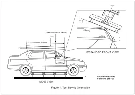
The strength of the roof structure to occupant protection in real-world rollover crashes, requiring the maximum moving distance of the roof structure should be less than 127 mm (5 in.) when the induced load is 1.5 times the vehicle weight.
For the test, the passenger car shall be rigidly placed or positioned on a horizontal surface with the doors locked and the window closed. Furthermore, a flat, rigid block with a lower surface a rectangle measuring 30 inches wide by 72 inches long (762mm X 1829mm) shall not move more than 5 inches(127mm), measured as the distance between the original location of the lower surface of the test device and its location as the specified force level is reached, when it is used to apply a force of 1.5 times the unloaded vehicle weight (UVW) or 5000 lbs(22224N), whichever is less, to either side or forward edge of the vehicle.
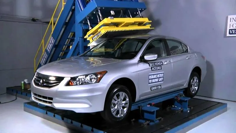
This test can be conducted on either side of the roof structure, the front left or the front right side but not on both sides in one single test and still meet the requirements of the test. The rigid plate shall not move faster than 0.5 inches/second and the force applied on the plate shall not exceed the lesser of 1.5 times the unloaded vehicle weight (UVW) expressed in kilograms multiplied by 9.8 or 5000lbs (22240N).
Also, the direction of the force shall be downward and perpendicular to the lower surface of the rigid plate and such that it moves in a straight line without rotation. The duration of the test shall not exceed 120 seconds. The longitudinal axis of the plate is pitched forward at a 5 º angle as viewed from the side of the passenger car
The lateral axis or the roll of the plate is such that it forms a 25 º outboard angle with a horizontal surface as viewed from the front of the passenger carRoof -
An automobile roof or car top is the portion of an automobile that sits above the passenger compartment, protecting the vehicle occupants from the sun, wind, rain and other external elements or environment conditions.
The roof is joined with the pillars on all sides, and the roof is reinforced with the front roof rail, rear roof rail and bow roofs. The rails are joined with the roof with the help of mastic sealant because we don't want to disturb the aesthetic look of roof surface.
Roll Over Test regulations and requirement
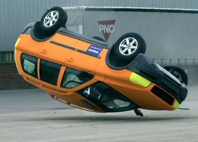
The rollover test conducted by NHTSA subjects vehicles to a handling maneuver called a fishhook, which is a term used for a quick left-right turn at speeds ranging from 35 to 50 miles per hour. The operation is a simulation of the driver overdoing the vehicle steering, usually happens during emergency situations.
Gap and Flushness requirements
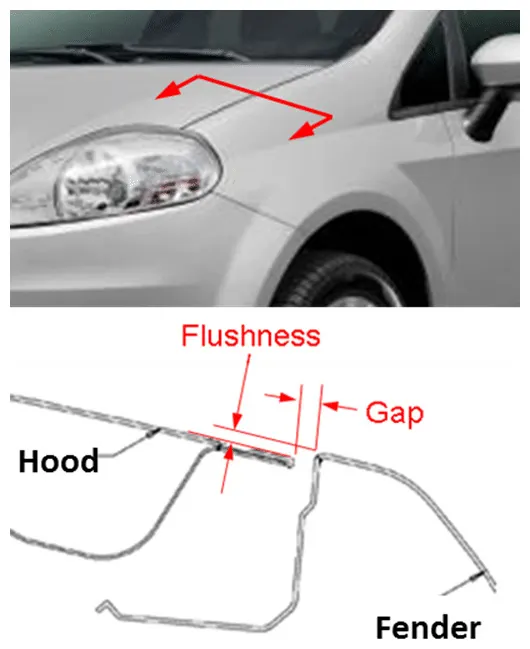
The gap, gap parallel (equal distance between two gaps over a distance) and flush are the terminologies involved in automotive industry which influences the customer appeal. The gap and flush measurements of side closure are shown in the below picture.
The gaps and flushes are given to the hood of the car with fender and sidewall by adjusting the hinge and striker during assembly.
In case of an automotive design, gap and leveling between the adjacent parts, known as gap and flushness, respectively, can be cited as examples of aesthetic dimensional requirements that influence customer's perception of quality
Manufacturing process
Stamping is a forming process performed on sheet metal by a series of stamping stations. The stamping process used to produce mass quantities of finished products [7]. The stamping of sheet metals can be defined as the process of changing the shape of the sheet metal blank into a useful shape in the plastic deformation state, using a die and a mechanical press; stamping is considered a net shaping process. Generally, the automotive stamping focuses on two modes of stamping: deep drawing and stretch forming. The deep drawing mode is when the sheet metal is formed (drawn) from the binder by the punch. The stretch forming mode is when the clamping pressure of the holding down ring is very high, such that the friction forces in the flange are high enough to allow the material to flow in. The formability of sheet metal can be further analysed from the metal flow patterns within the die cavity [8]. In stamping, there are three main patterns of metal flow: elastic flow, plastic flow, and rigid movement.
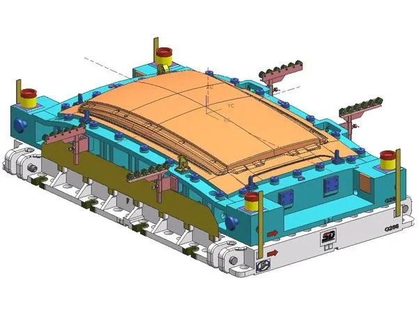
Metal stamping is the manufacturing of metallic components by applying an extreme amount of pressure to blank pieces or sheets of metal. The purpose of this metal stamping process is to be able to produce formations of any shape and size desired out of the metal sheet. It has strongly associated with the automobile industry because each car has many parts that are made from steel. Outer car panels, like hoods and fenders, are common examples of parts made using metal stamping processes. Sheet metal stamping presses act as carriages to carry other machines. Dies are fairly simple machines that fit inside and fastened to a press [9]. The steel sheet cuts according to the size of the part and is bent and cut in a stamping machine to make parts such as car doors, roofs, and hoods [3]. In automobile manufacturing process, 60% to 70% of the metal parts are processed by the plastic forming, and a metal forming completes stamping process, such as a variety of car body panels, car parts support, engine exhaust pipe and muffler, hollow camshaft, oil pan, engine cradles, frameworks, structures horizontal beam, etc., are all positive by the precision metal forming technology. Stamping process is the so-called means of stamping parts of the adaptation process that designed in size stampings, precision and base size, structure, and shape with the pressing requirements of processing technology
Components of the roof
The roof consist of the following support sections
- Roof
- Front Roof Rail
- Rear Roof rail
- Bow Roof
- Reinforcement Roof Center
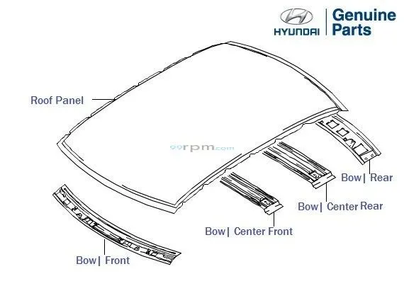
ROOF
The roof area is created from the styling surface .The roof is the styling surface which is coupled with the rails and panels inside to make it a stronger and stiffer component.The main area in the ditch is used to join the reinforcement components.The rail supports of the roof are attached to the Ditch Area using Spot welds since it is not a styling surface and remains concealed.Headroom Clearance, visibility criteria, clearance for Windshield and Back door are some of the factors to be considered while designing the Ditch Area.
The Ditch Area is the extended portion of the main Roof concealed by other BIW panels. The rail supports of the roof are attached to the Ditch Area using Spot welds. since it is not a styling surface and remains concealed. The front , rear and side ditch area is created by input from the master section.the embosses are created to increase the strength after curvature study
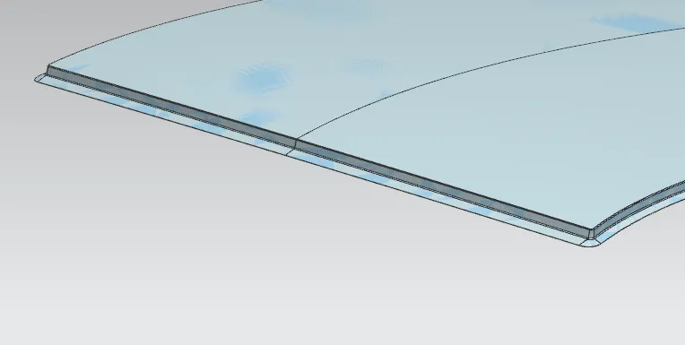
front ditch area
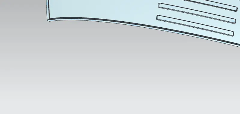
side area
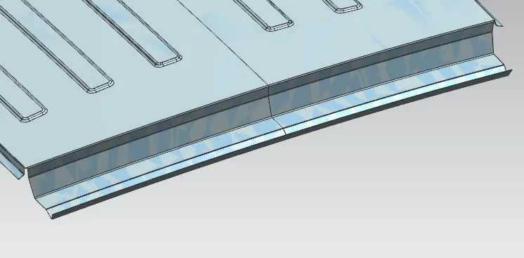
rear ditch area
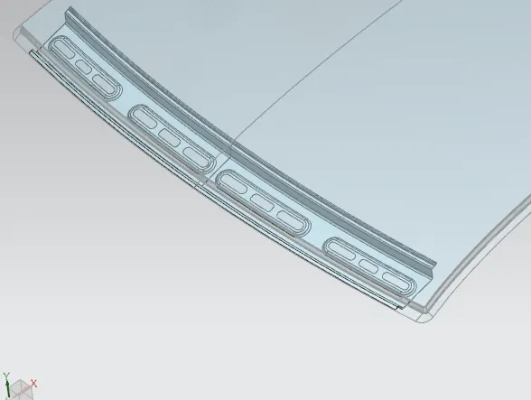
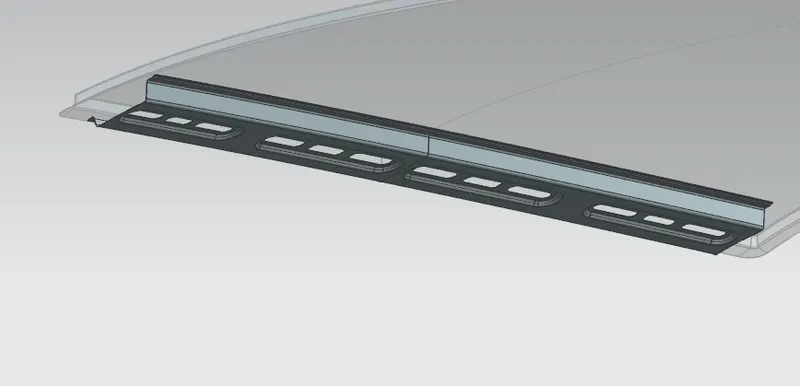
FRONT ROOF RAIL
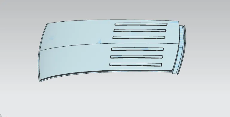
Front roof rails are used in the assembly of a roof in which it provides mounting provisions to windshield glasses and. It is designed with support requirements, visibility criteria, and headroom space in mind. The major design factor considered is the headroom clearance. A draft angle is provided keeping in mind the deep drawing operation. The Wind Shield end flange is the exact offset of the roof surface. The bottom most flange is decided after taking into consideration the visibility criteria and the Headroom Clearance of the passenger. Spot Welds are applied at Wind Shield end of the rail and the other end is joined with the roof using Mastic Sealants which also contributes to increased strength.This is the part that connects the roof ditch panel to the A-pillar of the car. Except for the roof panel all other parts provide strengthening aids to the roof panel. The Front rail is welded to the A-pillar and the roof panel. The front rail comes in the front part of the vehicle. The front rail upholds the rooftop outside shell at the front end. It is mounted with assistance rooftop rail fortress on the two terminations. The rails are equipped with embosses to improve the strength over the length and the rail is connected with the external board utilizing mastic sealants on one side and the other joinery is spot welded.
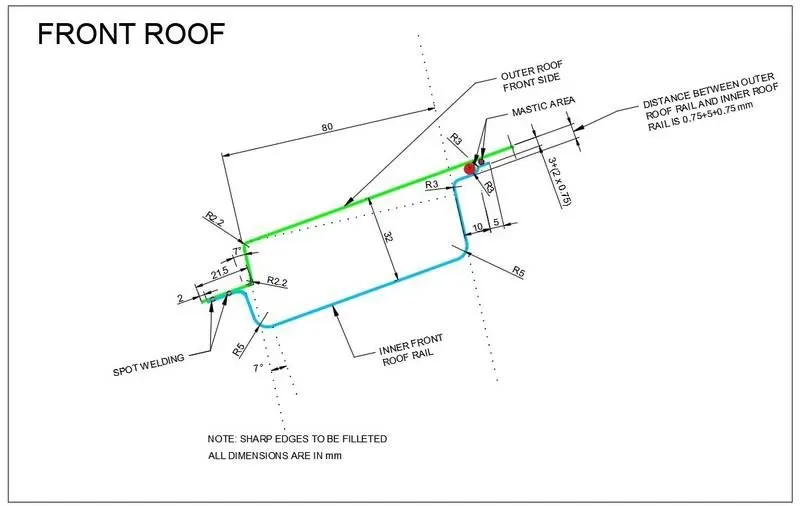
the master section for front roof rail
REAR ROOF RAIL
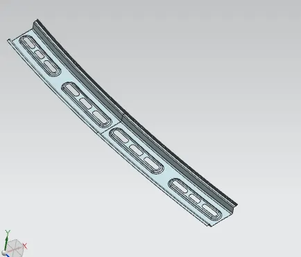
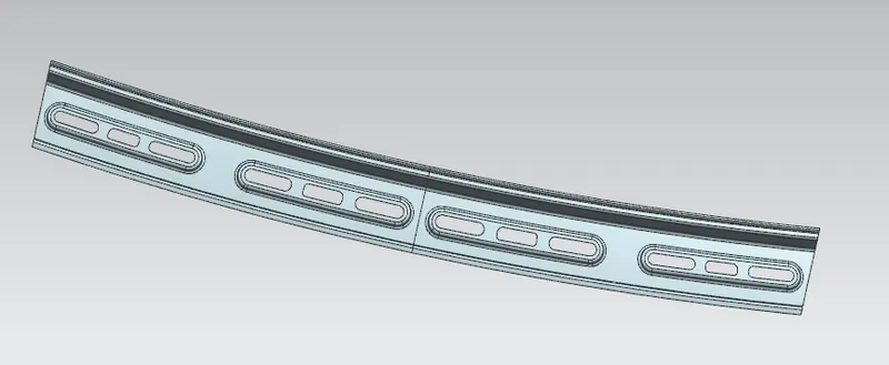
It is the support which is joined to the Back Door and the Body Side Outer and the inner panels. It is also usually made from Body Side Outer scrap and therefore the thickness of the rail is 0.75 mm. Similar to the Front Roof Rail design, we have to take into consideration the rear Headroom Clearance and the rear visibility criteria while designing the Rear Roof Rail. Inputs from the backdoor design is also taken to accommodate the required clearance. Spot Welds are applied at the Back door end of the rail and the other end is joined with the roof using Mastic Sealants. The Rear roof rail is used to provide strength to the roof panel front and it also acts as a link between windshield glass, roof panel, and headliner.
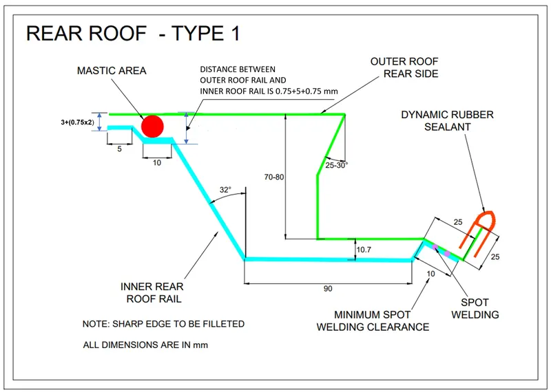
the master section for rear roof rail
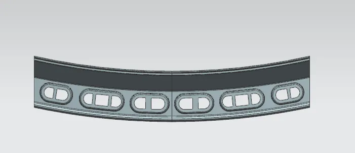
CENTRE ROOF RAIL (REINFORCEMENT CENTER)
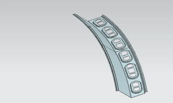
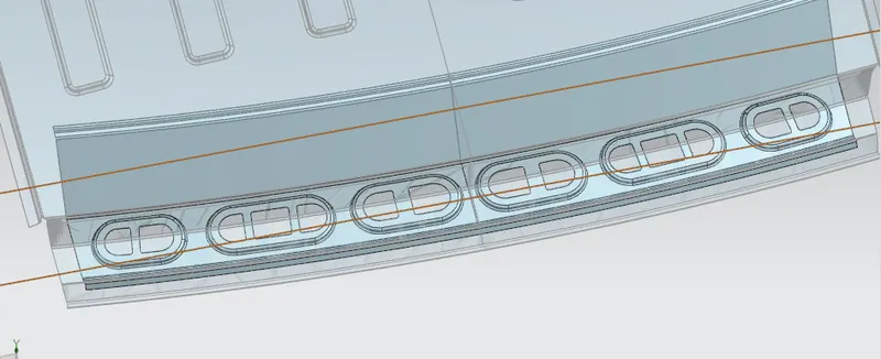
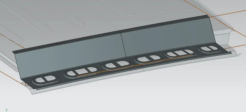
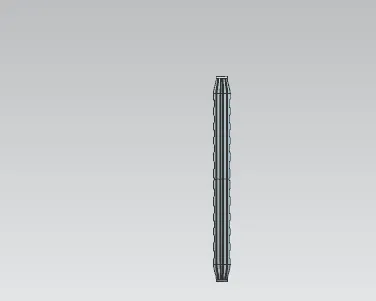
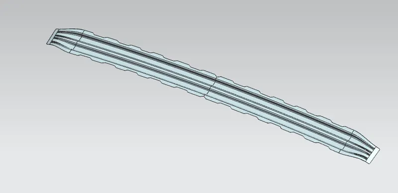
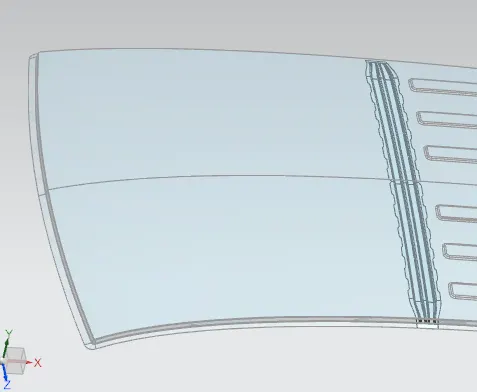
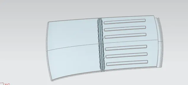
The reinforcement centre is used as a cross member between bodyside LH & RH respectively. Similar to other Rails design, we have to take into consideration the Headroom Clearance and the visibility criteria while designing the Centre Roof Rail and Bow Roofs. But unlike the Front and Rear Roof Rails, Spot Welds are not applied for joining these rails to the roof. Instead, Mastic sealants are introduced at both the ends since Centre Roof Rail and Bow Roofs are fully positioned under the Styling surface of the Roof. For increasing the strength of the rails, embossing is done. To reduce the weight of the material used, a different styling has been followed with a thickness of 0.75 mm.
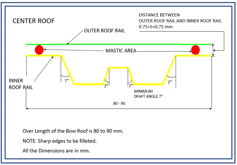
master section for center roof rail
BOW ROOF RAIL:
The bow roof rails provide additional support to the roof and they are positioned in such a way that they provide maximum support to the roof. Care must be taken so that they do not intrude into the headroom requirements of the car. Bow roof rails are an optional feature provided as required by the design. Small cars may have none while large ones may have 3 or more, they may also be integrated into the centre roof rail in some cases. The roof is fixed to the roof rails with the use of mastics while the ends are spot welded.
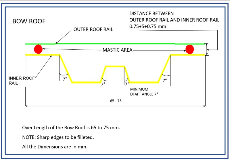
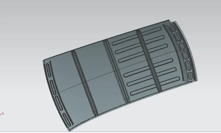
The Bow roofs are given to improve the torsional stiffness and load-bearing capacity of the roof structure. The number of bow roofs given will depend on the overall segments of the roof. The more expanded the roof more the bow roofs are fused into the BIW layout They are associated with the outer board using mastic sealants. Each mastic point will have up to 80 mm indirect powerful area. The arranging of bow roofs is done ward on curve assessment. The heat distortion criteria and snow load criteria are checked to examine the circumstance of the bows in various conditions.
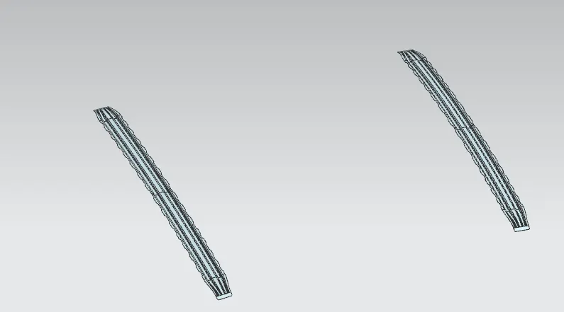
front and rear bow roof
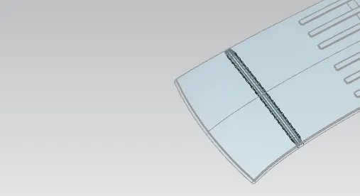
front bow roof
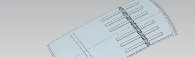
rear bow roof
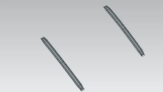
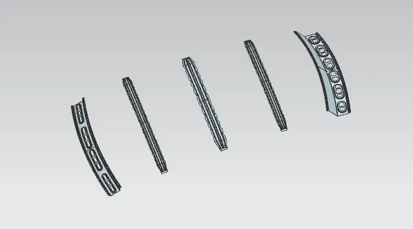
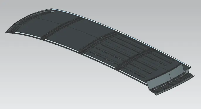
ROOF ASSEMBLY
ANALYSIS
Heat distortion condition
Heat distortion temperature is the temperature at which the metal softens and deforms under a specific load. Roof of a car is probably the only component which is exposed to sun for almost all the time, so this study is done to check the ability of the roof to withstand high temperature with respect to the positioning of the reinforcements which contribute to increased strength.
This study is done to check the ability of the roof to withstand high temperature with respect to the positioning of the reinforcements which contribute to increased strength
Bow–Roof Prediction Formula
W = [1.73 x 10^(-3) x L] + [1.85 x 10^(-8) x (R^2)/t] + [ 1.10x10^(-3) x l] - 2.68
Where,
L = Roof Length in X-Direction[mm](Roof dimension in 0-Y)
R = Roof curvature
R = 2(Rx*Ry)/(Rx+Ry)
Rx = X curvature
Ry = Y curvature
t = Roof plate thickness [mm]
l = Bow Roof Span [mm]
Judgment Condition
OK< 2.7
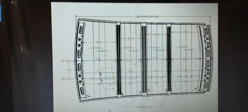
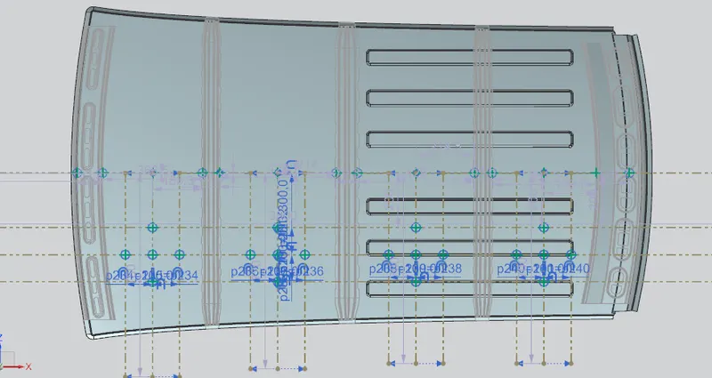
To calculate the heat distortion criteria, first we have to find the x and y curvatures. For that, we have to follow the below steps.
- Create a sketch on the top of the roof and the draw a horizontal construction line at the center of the roof in y direction.
- Offset the center line 300 mm below and name it as -3Y line.
- From the -3Y line, offset the construction lines to 100 mm on both sides.
- Now, find the distance between the adjacent rails, and draw a line exactly at the middle of the both rails.
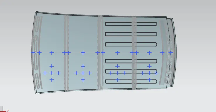
- Now, We got the five intersection points, create points there and exit the sketch.
- Project the points to the roof of the car.
- Finally, draw the 3D 3 point arcs with the help of that points and find the length of the arc.
| SL NO | ROOF RAIL | Rx | Ry | R | L | I | t | W | RESULT |
| 1 | FRR-BRR1 | 5739.979 | 2471.060 | 3454.820 | 2029.450 | 366.513 | .75 | 1.234 | OK |
| 2 | BRR1-CRR | 5012.149 | 6032.359 | 5475.134 | 2029.450 | 427.988 | .75 | 1.301 | OK |
| 3 | CRR-BRR2 | 4021.833 | 10351.28 | 5792.918 | 2029.450 | 429.018 | .75 | 1.302 | OK |
| 4 | BRR2-RRR | 3303.521 | 14228.27 | 5362.075 | 2029.450 | 381.464 | .75 | 1.250 | OK |
The all W value is below 2.7. the heat distortion criteria is fullfilled.
Snow Load Criteria:
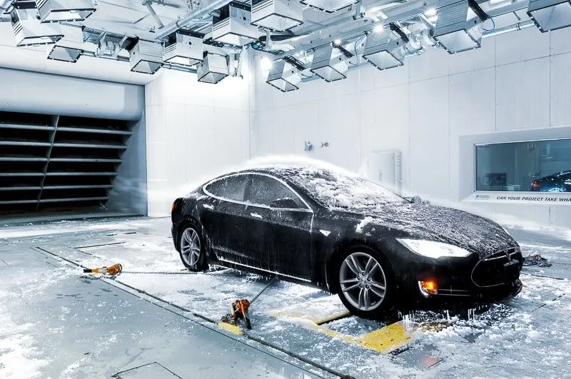
Snow load criteria study is done to check the ability of the roof to withstand snowfall and bounce back to its original shape without any permanent deformation once the load is removed.
Snow Load Prediction Formula
Qr = [Iy x t2] / [α x s x [(Rx + Ry)/2]2 x 10-8]
Note: The Qr value given over here is correct. There was a typo error in the formula given in the video.
Where,
α = My x Lx2 x 10-12 , My = Y(Ly-Y)
t = Roof plate thickness [mm]
Ly = Distance between the front and rear roof Rails on the Vehicle along with 0Y[mm]
Length of Roof panel with the center point between Roof rail Front /Rear as the front and rear reference point.
Lx = Distance between the Left and Right end of the roof on the Roof BOW [mm]
The width of the roof panel is exposed on the surface.
Y = Distance front Front Roof Rail to Roof BOW[mm]
s = Distance for which Roof BOW bears divided load [mm]
s = L1/2 + L2/2
Iy = Geometrical moment of inertia of Roof BOW (Y cross-section )[mm4]
Rx = Lateral direction curvature radius of roof panel Y cross-section on Roof BOW [mm]
Roof panel curvature Radius of the Length Lx in Front view
Ry = Longitudinal Direction curvature radius of the Roof panel X cross-section on Roof BOW [mm]
Roof panel X curvature radius of length s in Side view
Judgment condition
Qr ≥ 3.1
250 ≤ s ≤ 380
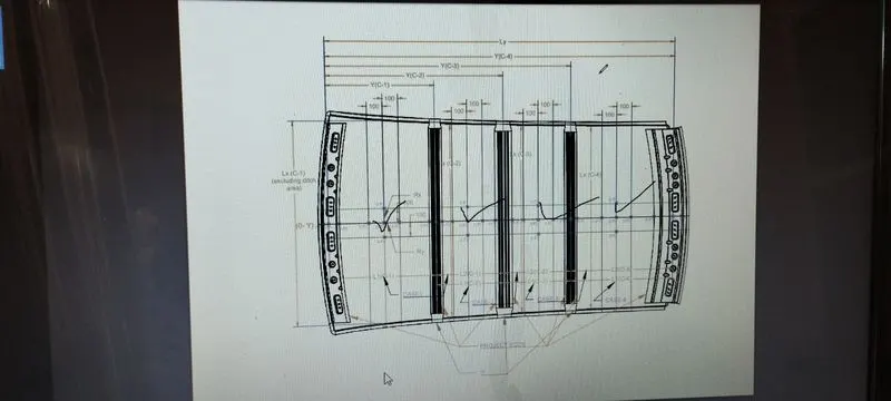
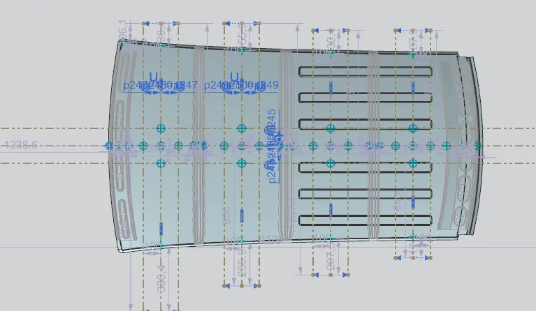
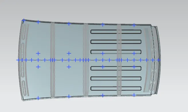
The snow load condition calculation is similar to the heat distortion. Here we have to follow the following steps to draw the reference sketch
- Create the sketch on the top of the roof and draw a horizontal line at the center of the roof.
- Offset this center line 100 mm on both sides.
- Draw the vertical lines at exactly at the center of the two adjacent rails.
- Offset this lines to 100 mm on both sides. Convert all lines into construction lines.
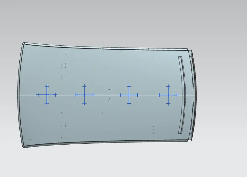
- Create the intersection points between the lines and project those points to the roof.
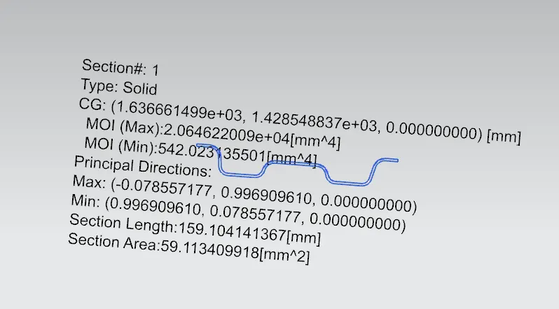
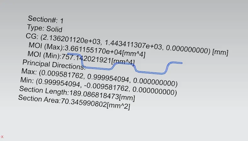
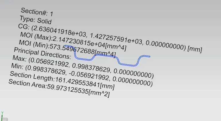
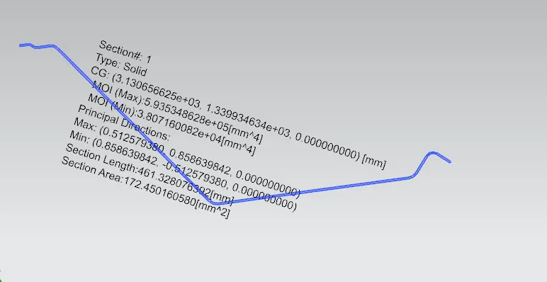
moment off inertia calculation for snow load prediction
front roof rail
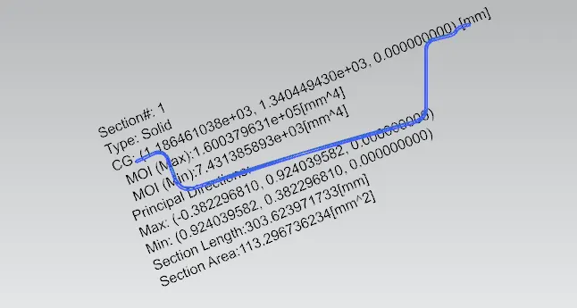
front bow roof
center roof rail
rear bow roof
rear roof rail
| SL NO | ROOF RAIL | Rx | Ry | Ly | Lx | L1 | L2 | Iy | Y | `alpha` | S | t | QR | RESULT |
| 1 | FRR-BRR1 | 3397.92 | 1848.74 | 2029.45 | 1139.12 | 460.58 | 500.04 | 7431.38 | 460.58 | 0.937 | 480.29 | 0.75 | 134.8 | OK |
| 2 | BRR1-CRR | 2932.17 | 5942.96 | 2029.45 | 1088.14 | 500.04 | 499.58 | 542.023 | 500.04 | 0.905 | 499.79 | 0.75 | 3.42 | OK |
| 3 | CRR-BRR2 | 4252.99 | 10800.39 | 2029.45 | 1059.18 | 499.58 | 504.07 | 757.142 | 499.58 | 0.857 | 501.79 | 0.75 | 1.74 | NG |
From the obtained results, it has been observed that one of the Qr values should not satisfy the judgement condition. So the model can be passed over to the styling team to change the curvature or position of bow roof rails are changed towards the weaker sections or embosses are created on the roof to improve the strength.
To improve the strength in the weak sections, EMBOSS is created in weaker section
DRAFT ANALYSIS
The Draft Analysis command enables you to detect if the part you drafted will be easily removed. This type of analysis is performed based on colour ranges identifying zones on the analyzed element where the deviation from the draft direction at any point, corresponds to specified values.
the draft analysis is carried out for all roof rails
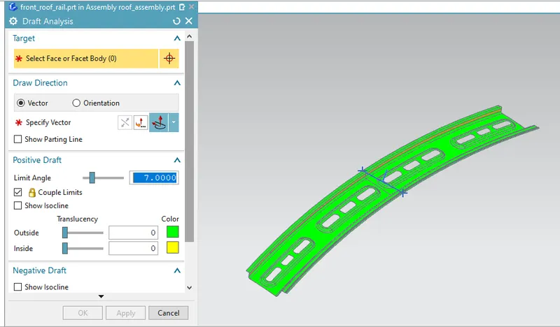
draft analysis for front roof rail
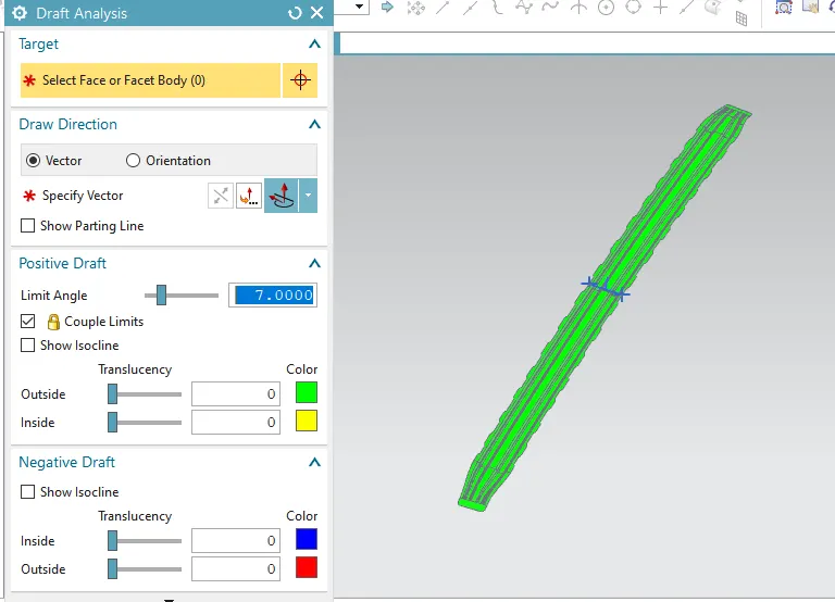
draft analysis for front bow roof
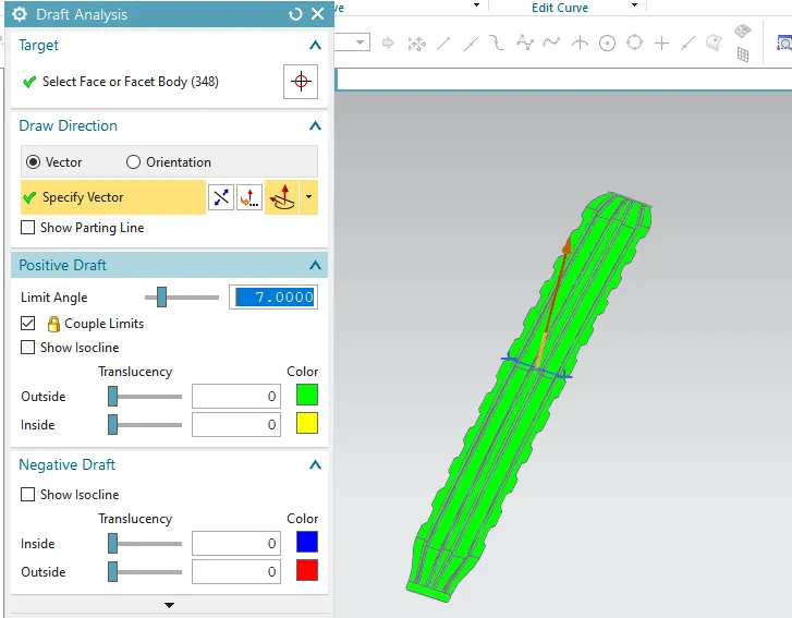
draft analysis for center roof rail
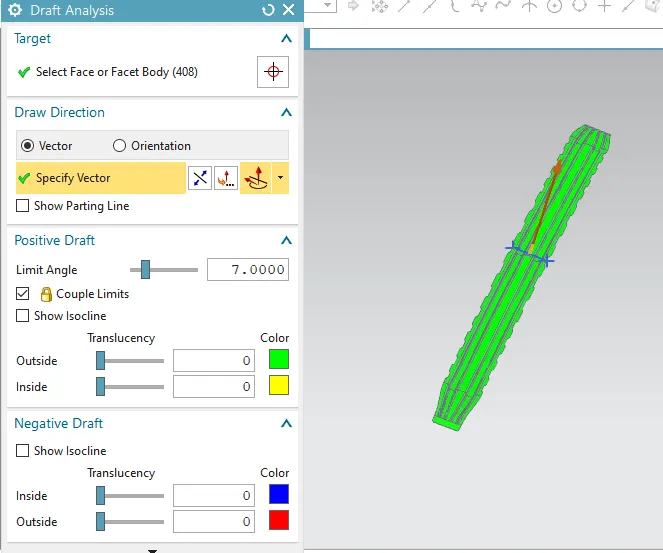
draft analysis for rear bow roof
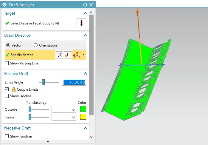
draft analysis for rear roof rail.
Draft analysis is done for all parts in assembly and it fullfill the criteria of tool opening angle of 7 degrees
CONCLUSION
- Roof assembly is designed with its components by following the master section
- Design contain 1 Front roof rail, two bow roofs, 1 center roof rail and 1 rear roof rail.
- Draft analysis is done for all the parts and it fullfill the crieteria.
- Curvature study on the roof is done and perform calculations for
- Heat distortion crieteria
The all W value is below 2.7. the heat distortion criteria is fullfilled.
2.snow load crieteria
From the obtained results, it has been observed that one of the Qr values should not satisfy the judgement condition. So the model can be passed over to the styling team to change the curvature or position of bow roof rails are changed towards the weaker sections or embosses are created on the roof to improve the strength.To improve the strength in the weak sections, EMBOSS is created in weaker section