Roof challenge
AIM
For the Given Roof styling, Develop the essential flanges and reinforcements, Provide appropriate dimension and check for Draft analysis and also submit your section modulus report on the 0-Y section.
Start with the creation of a roof ditch area the tool opening angle is only 3 degrees.
Do a curvature study on the roof and perform calculations to determine the position of the Bow-roof.
ROOF
An automobile roof or car top is the portion of an automobile that sits above the passenger compartment, protecting the vehicle occupants from sun, wind, rain, and other external elements.
The roof itself may be constructed of soft or rigid material. Soft-tops are made of vinyl, canvas or other textile material; hard-top convertibles have roofs made from steel, aluminium, plastic or carbon fibre composites.
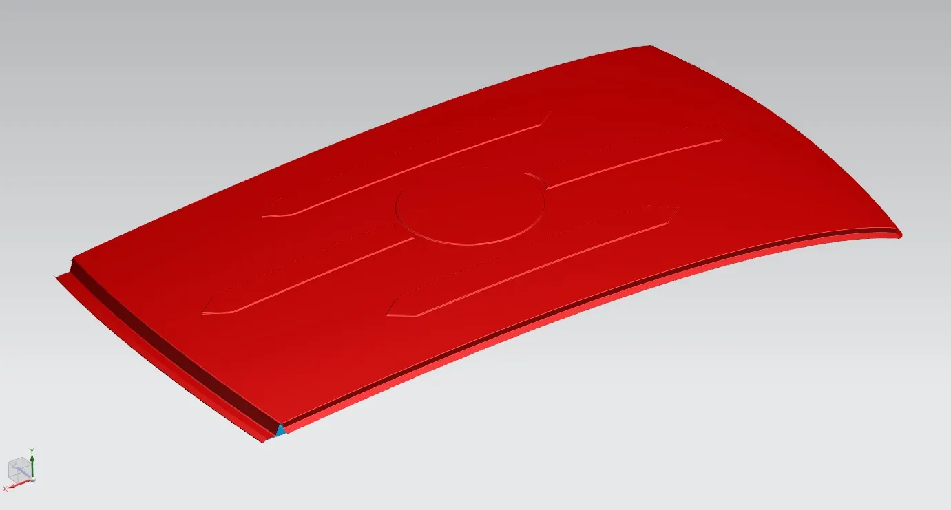
In the past roof was introduced as cover for passenger compartment but later on, it also used as a luggage carrier, sunroof and in recent past years with the introduction of the solar panelled electric vehicle got a major boost in the automotive industry.
Roof has the following functions:
- protects from external damage
- prevents passenger and vehicle from accidents
- luggage carrier
- design of the roof also affects in giving aerodynamic shape to vehicle
- sunroof
- solar panelled roof in EV
DESIGNING OF ROOF
About Automotive Vehicle Roof
Safety point of view vehicle roof plays very crucial role specially roll over kind of accidents, in which vehicle tips over onto its side of roof And vehicle rollover crashes are the causes of many fatalities and several head, neck and spine trauma around the world.
Therefore passenger safety is also very important parameter in front of OEM’s. It is not only a marketing strategy but also it is a obligation stipulated by international standards that are now place in several countries, as well as a governmental requirement. For this reason strength is very important criteria for designing vehicle roof.
Roof Material Properties
Density : 7890 kg/m3
Young's modulus : 210000Mpa
Poisson's ration : 0.3
Yield stress : 210 Mpa
Metal Roof Mass : 11.2kgs
Thickness : 0.75mm
Joining process : Metal roof with spotweld connections
Standard experimentation setup
Safety point of view vehicle roof plays very crucial role specially roll over kind of accidents, in which vehicle tips over onto its side of roof. And vehicle rollover crashes are the causes of many fatalities and several head, neck and spine trauma around the world. Therefore passenger safety is also very important parameter in front of OEM’s. It is not only a marketing strategy but also it is a obligation stipulated by international standards that are now place in several countries, as well as a governmental requiremen.
For this reason strength is very important criteria for designing vehicle roof.
The strength of the roof structure to occupant protection in real world rollover crashes, requiring the maximum moving distance of the roof structure should be less than 127 mm (5 in.) when the induced load is 1.5 times of the vehicle weight.
For the test the passenger car shall be rigidly placed or positioned on a horizontal surface with the doors locked and the window closed. Furthermore, a flat, rigid block with lower surface a rectangle measuring 30 inches wide by 72 inches long (762mm X 1829mm) shall not move more than 5 inches(127mm),measured as the distance between the original location of the lower surface of the test device and its location as the specified force level is reached, when it is used to apply a force of 1.5 times the unloaded vehicle weight(UVW) or 5000 lbs(22224N),whichever is less ,to either side or forward edge of the vehicle.
- This test can be conducted on either side of the roof structure, the front left or the front right side but not on both sides in one single test and still meet the requirements of the test .
The rigid plate shall not move faster than 0.5 inches/second and the force applied on the plate shall not exceed the lesser of 1.5 times the unloaded vehicle weight (UVW) expressed in kilograms multiplied by 9.8 or 5000lbs (22240N).Also the direction of the force shall be downward and perpendicular to the lower surface of the rigid plate and such that it moves in a straight line without rotation. Duration of the test shall not exceed 120 seconds.
The longitudinal axis of the plate is pitched forward at a 5 º angle as viewed from the side of the passenger car.
• The lateral axis or the roll of the plate is such that it forms a 25 º outboard angle with a horizontal surface as viewed from front of the passenger car.
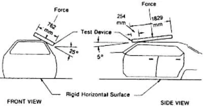
• The lower surface of the plate shall always maintain a tangential contact with the surface of the roof.
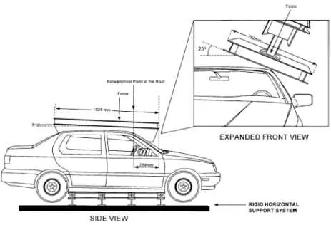
• The initial point contact is 10 inches (254 mm) from the leading edge of the plate and in line with the longitudinal axis on the lower side of the plate.
DESIGNED ROOF
Below picture referes that the master section for the Front roof rail.
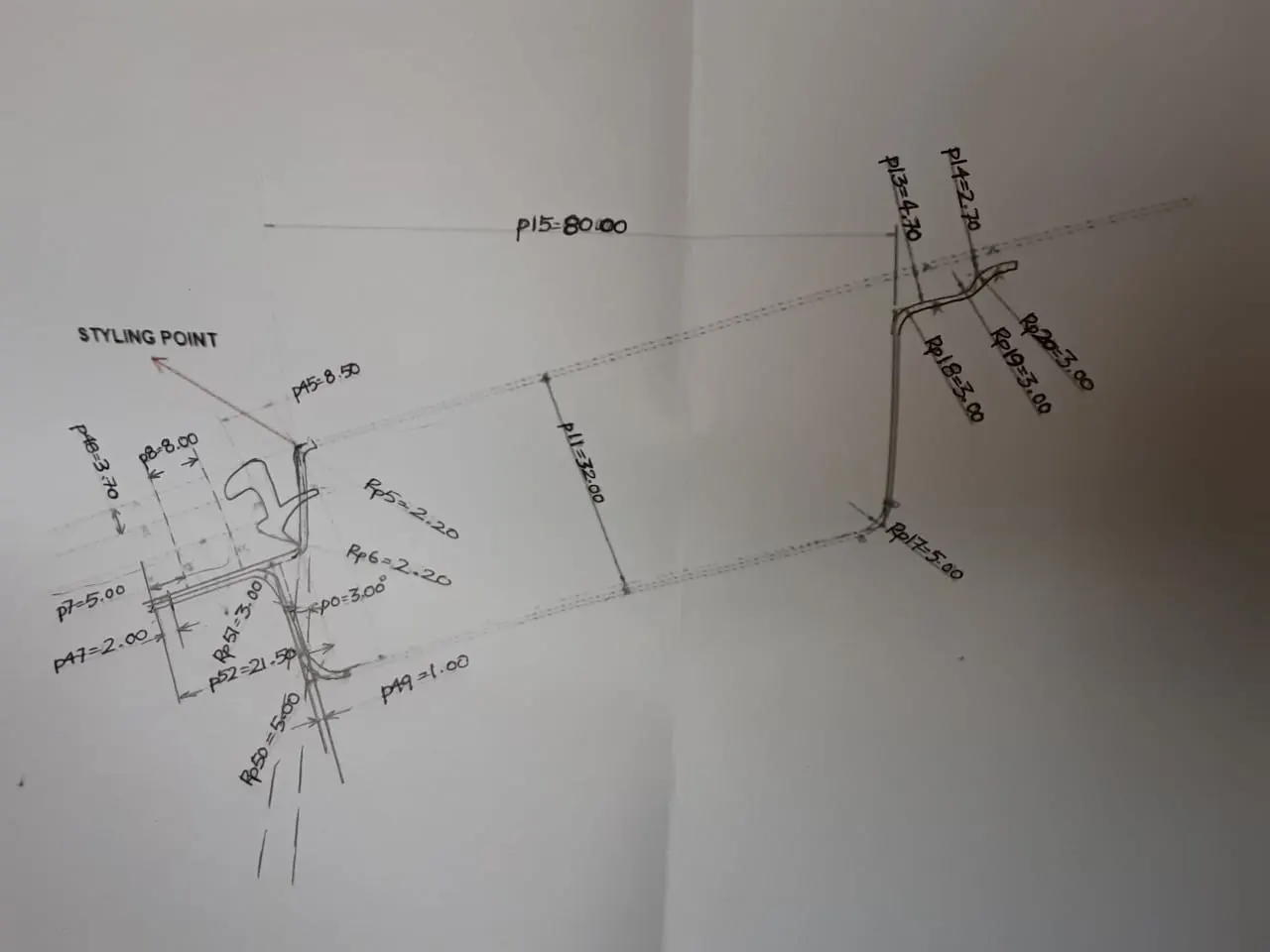
In the above picture as mentioned lot of dimesnions according to the research they got this value.
In the front end there is windshield joining to the front roof rail part,There we have to give some gap for mounting the front roof rail and the windshield mounting space.
In this case i left 5 mm for windshield rubber mount and some gap for masting sealants.
We should maintain atleast 3 to 5mm gap from the roof and the front roof rail rare part,Why becasue we have to merge with masting sealants.
We have to give 0.2mm for the tolerance.
FRONT ROOF RAIL
Below picture referes the designed Front Roof rail for the Car.It holds the Roof top.
Windshield glass and the Front Roof rail got attached here with the help of masting sealants.
we designing the Roof Rails for the extra strength to hold the roof.

I provided Some embosses for the extra strength for the front roof rail.We giving embosses for the strength to the component.
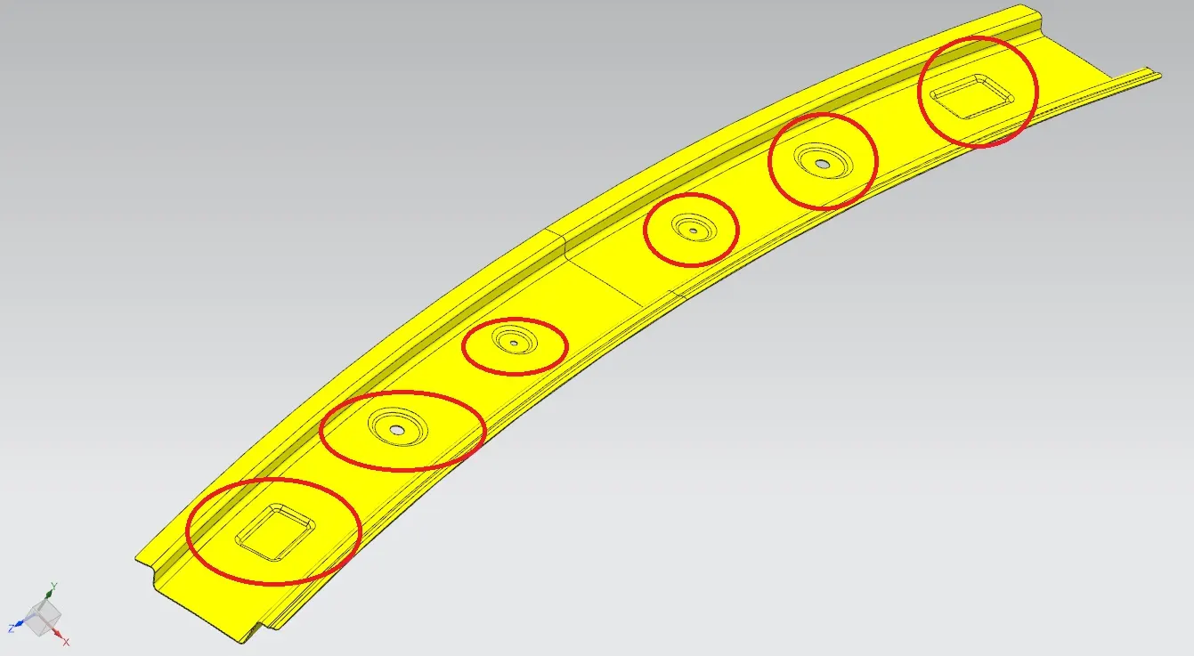
There is no sharp edges at the corners,If there is any sharp edges means it will effect while mounting.For this we should avoid sharp corners by filleting smooth edges.
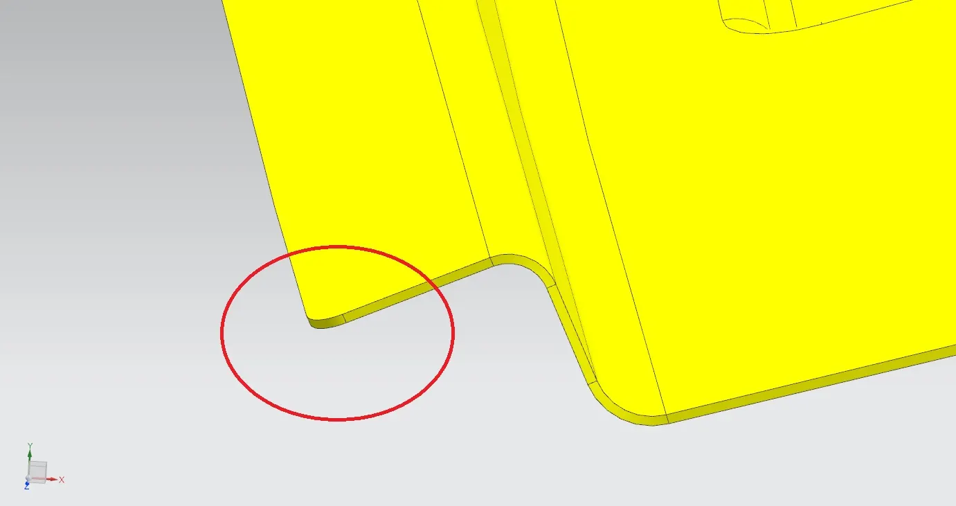
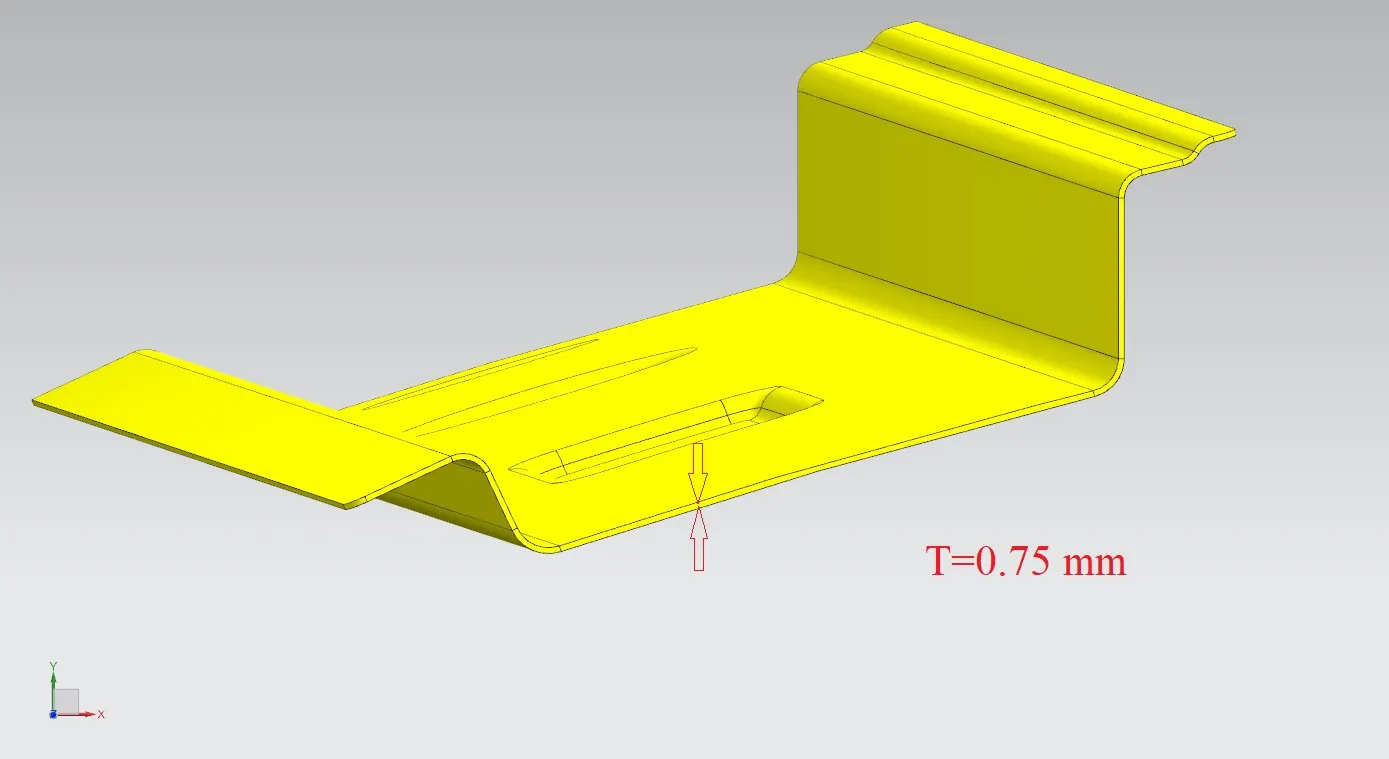
I maintained 0.75 mm thickness for the Front roof rail,Why because if we use more than 0.75 mm means there is increase in overall weight of the car leads to low performance,need more power,simply weight of the car increases.
This 0.75mm is the perfect and stardard thickness for the automotive sheet metal components.
Thickness for automotive sheetmetal components vary from 0.65 mm to 0.75 mm.
DESINGING OF BOW 1
Below picture referes that BOW1.
WHY NEEDED
If the curvature of the Roof stylish part is not good or its weak or if we need more strength then we need Roof BOWs.
In the below picture i designed BOW 1.I got good surface finish and i satisfied draft analysis.
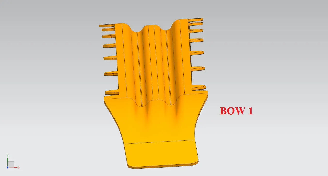
In the below picture there is extra mounting surface for mounting the bow to car body like A pillar.
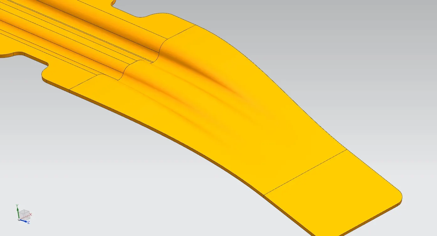
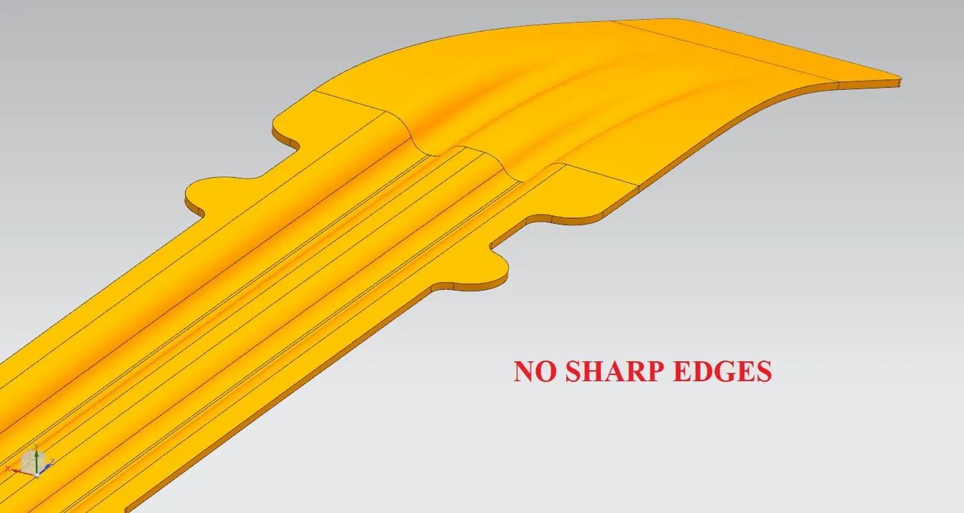
Below picture shows that there is no sharp edges at all as you can see i avoided every small sharp corners with the help of fillets.
If there is any sharp edges means it will effect while mounting.For this we should avoid sharp corners by filleting smooth edges.
MASTIC POINTS
Why Automotive uses MASTIC SEALANTS
Engineers are constantly faced with the challenges of sealing assemblies against air, dust, noise, and making sure that these assemblies do not squeak and / or rattle.
Sealants are materials that are for one time use only. Meaning, the whole assembly is replaced or the particular area that needs to be sealed will not be taken apart and put back together as part of its requirements.
Prevents excessive absorption of adhesive or penetration of liquid or gaseous substances.
- Reduction of Direct Labor Costs
Reduction of Indirect Costs/Inventory Management
Reduction of Scrap Materials
Material Cost Reduction
Ease of Accommodation of Engineering Changes
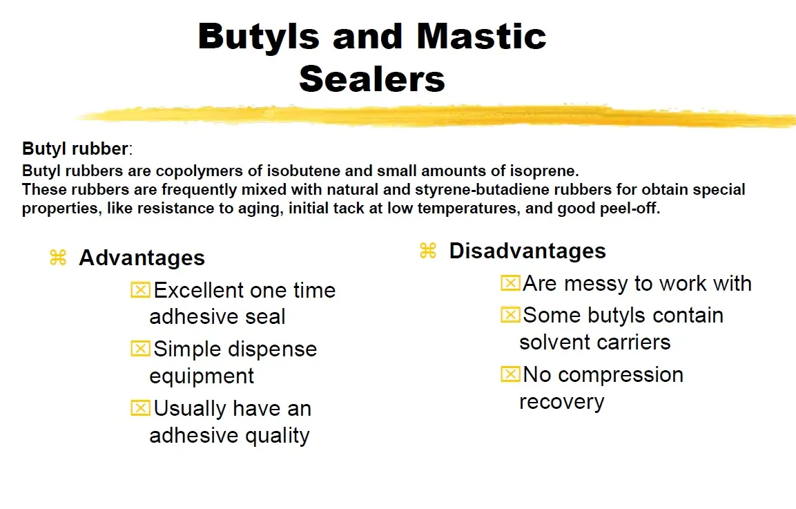
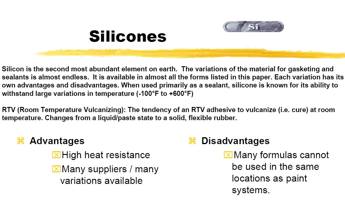
TYPES & ADVANTAGES AND DISADVANTAGES OF SEALANTS
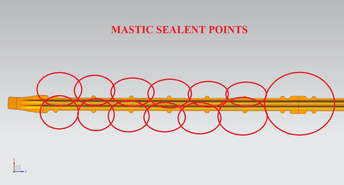
Below picture referes that the mastic sealant points for the BOW roof 1.
I maintained 80 mm gap between one mastic point to the other mastic points as you see in the picture.
CENTRAL ROOF RAIL & CTR REINFORCEMENT
In the below picture shows that central roof rail of the car.Material used for all the sheet metal components are steel and alluminium cars.
Steel for low end cars and Alluminium for high end cars.because aluminium is castier and lighter than steel.
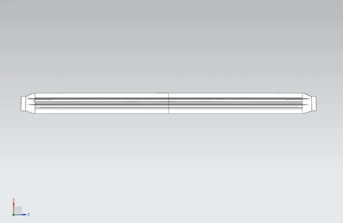
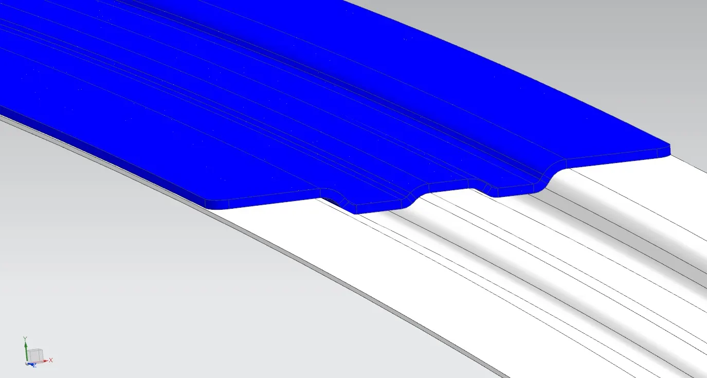
I provided extra strength for the CTR roof rail in this design.I provided extra reinforcement to the CTR roof rail.
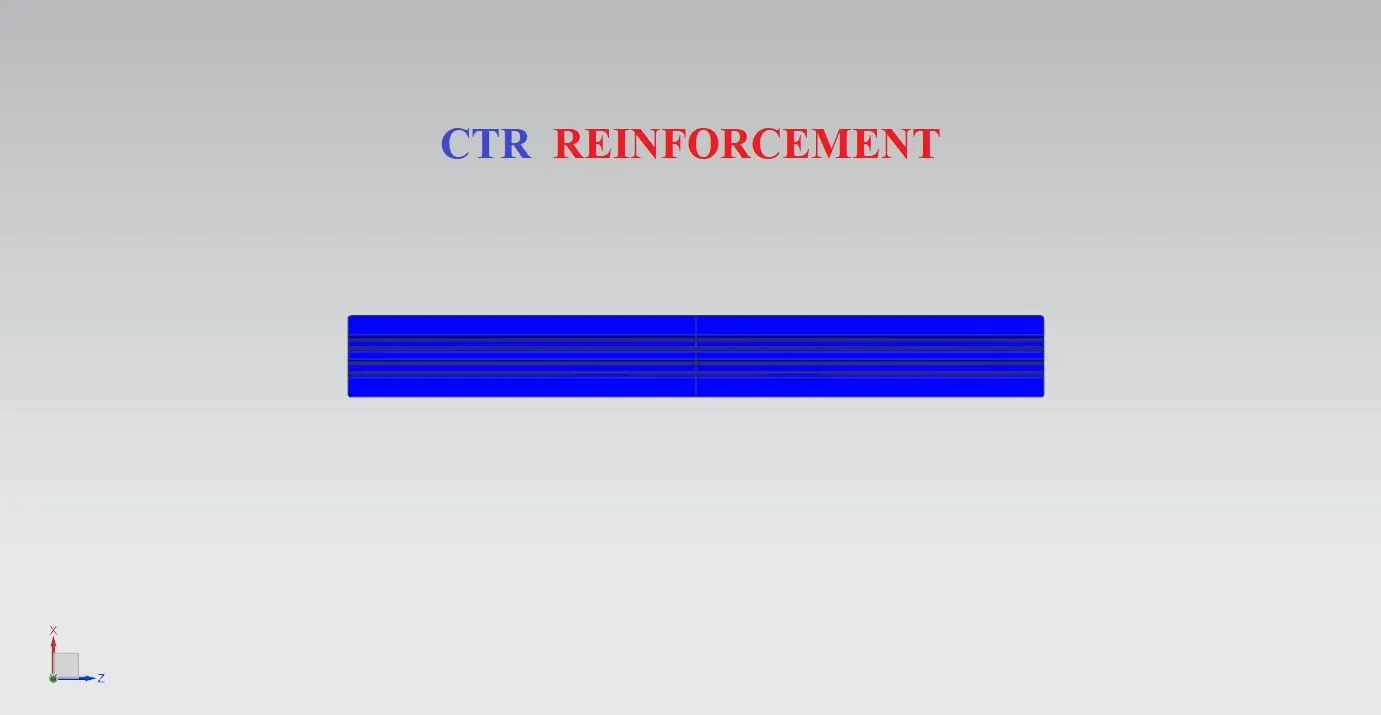
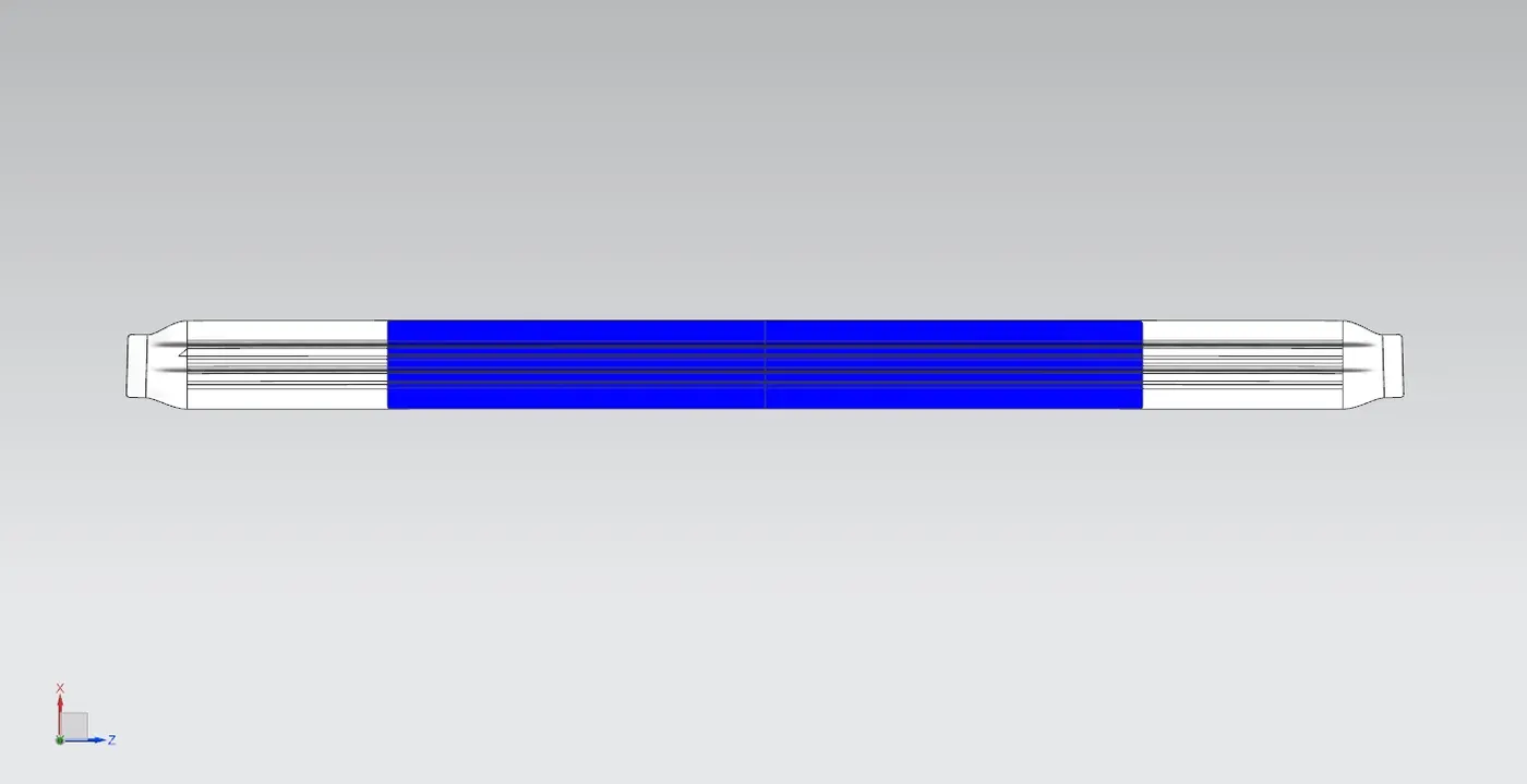
I designed CTR roof rail and the reinforcement with a tolerance of 0.2mm gap between these two.
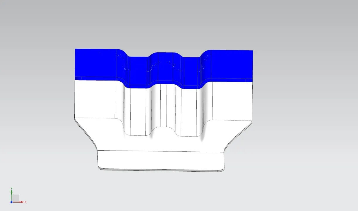
There is no sharp edges as you see in the below picture.
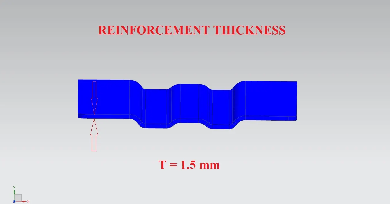
I provided reinforcement thickness about 1.5 mm as per the standards.
DESIGNING OF BOW 2
Below picture referes that BOW 2.
WHY NEEDED
If the curvature of the Roof stylish part is not good or its weak or if we need more strength then we need Roof BOWs.
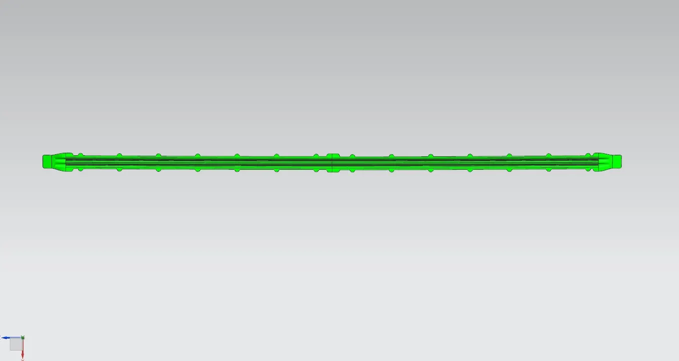
In the below picture i designed BOW 2.I got good surface finish and i satisfied draft analysis.
MASTIC POINTS
Why Automotive uses MASTIC SEALANTS
Engineers are constantly faced with the challenges of sealing assemblies against air, dust, noise, and making sure that these assemblies do not squeak and / or rattle.
Sealants are materials that are for one time use only. Meaning, the whole assembly is replaced or the particular area that needs to be sealed will not be taken apart and put back together as part of its requirements.
Prevents excessive absorption of adhesive or penetration of liquid or gaseous substances.
- Reduction of Direct Labor Costs
Reduction of Indirect Costs/Inventory Management
Reduction of Scrap Materials
Material Cost Reduction
Ease of Accommodation of Engineering Changes
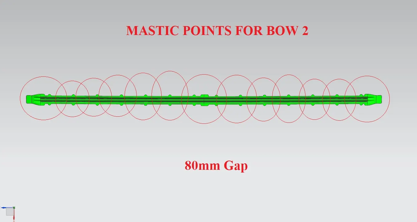
Below picture referes that the mastic sealant points for the BOW roof 2.
I maintained 80 mm gap between one mastic point to the other mastic points as you see in the picture.
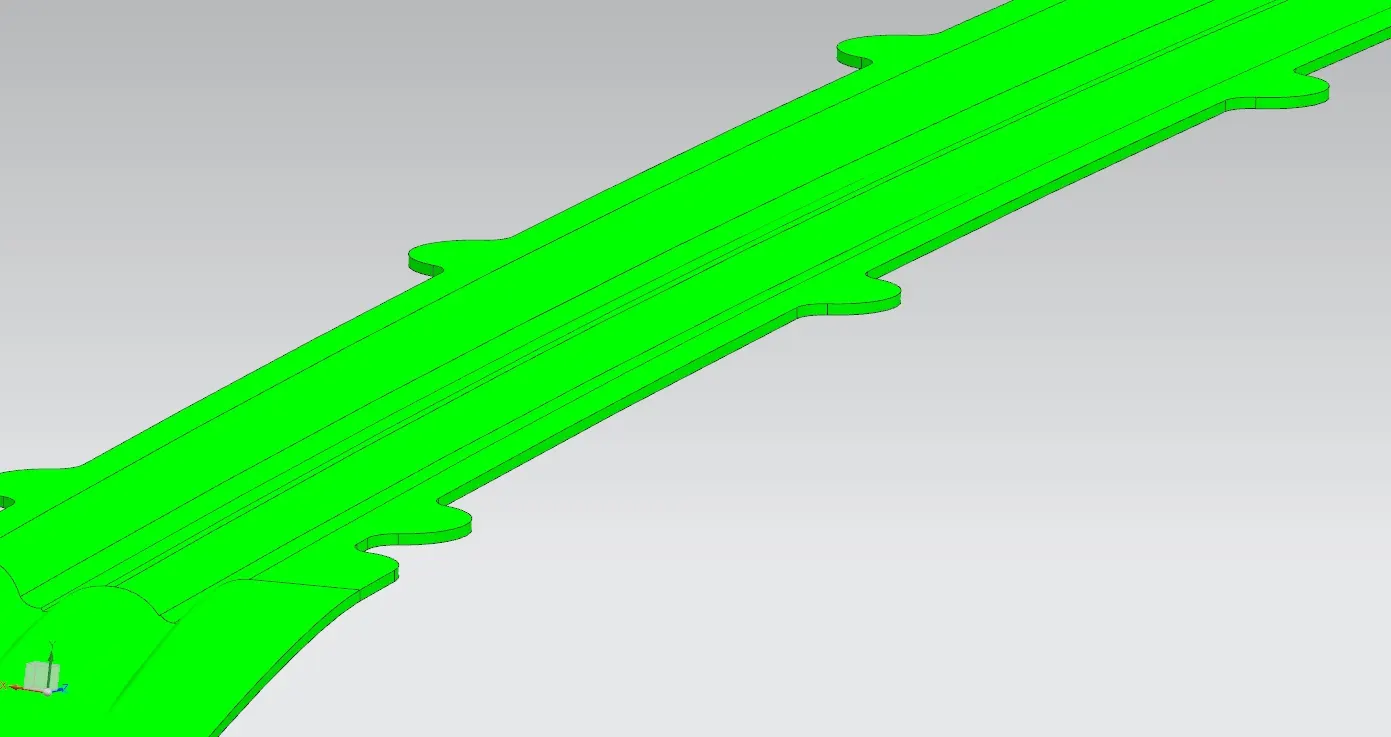
Below picture shows that there is no sharp edges at all as you can see i avoided every small sharp corners with the help of fillets.
If there is any sharp edges means it will effect while mounting.For this we should avoid sharp corners by filleting smooth edges.
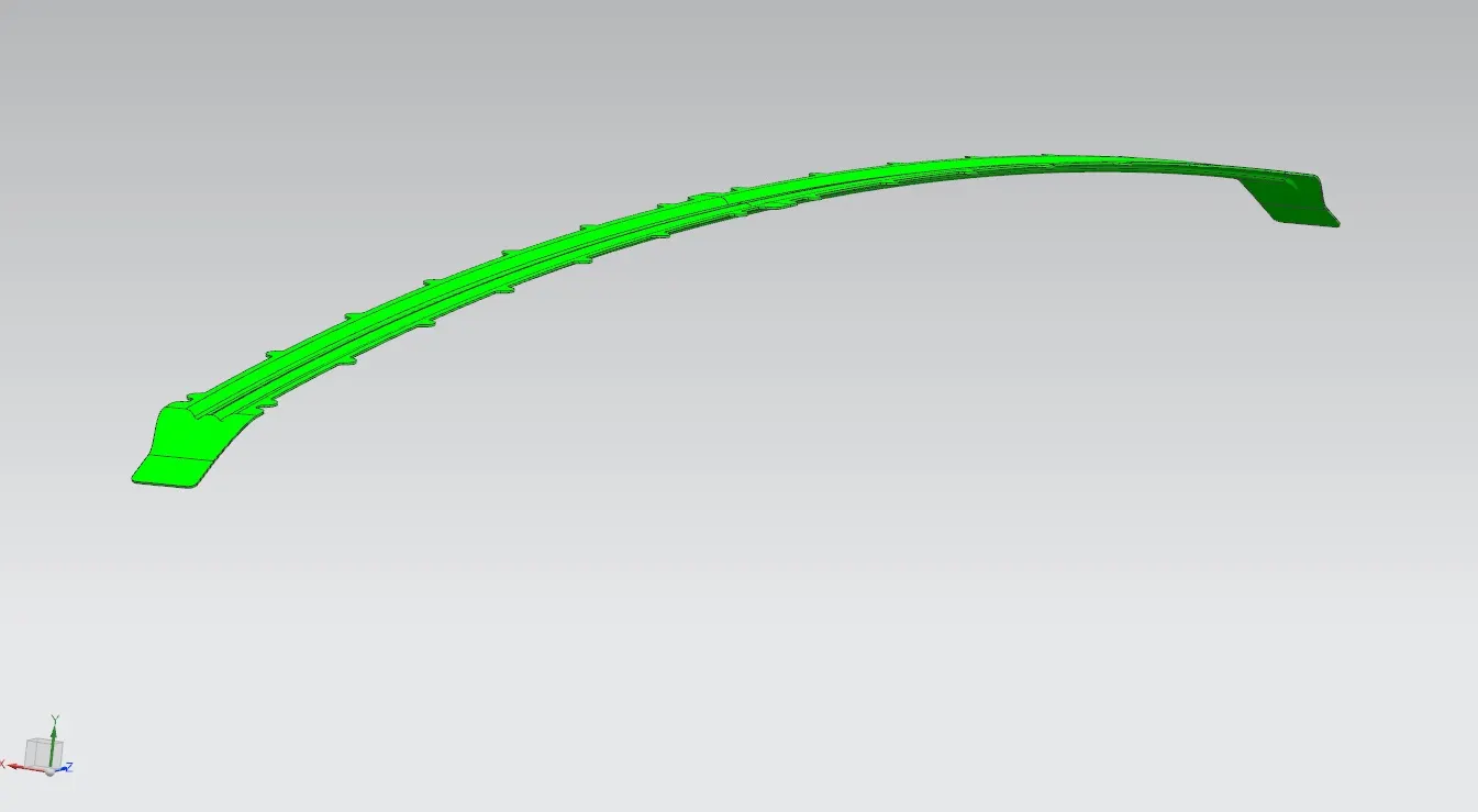
In the below picture there is extra mounting surface for mounting the bow to car body like A pillar.
REAR ROOF RAIL
Below picture referes the designed Rear Roof rail for the Car.It holds the Roof top.
Back Door and the Rear Roof rail got attached here with the help of masting sealants.
I maintained 0.75 mm thickness for the rearof rail,Why because if we use more than 0.75 mm means there is increase in overall weight of the car leads to low performance,need more power,simply weight of the car increases.
This 0.75mm is the perfect and stardard thickness for the automotive sheet metal components.
Thickness for automotive sheetmetal components vary from 0.65 mm to 0.75 mm.
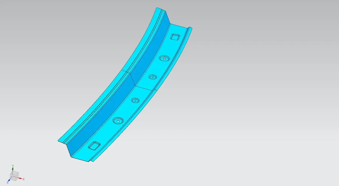
There is no sharp edges at the corners,If there is any sharp edges means it will effect while mounting.For this we should avoid sharp corners by filleting smooth edges.
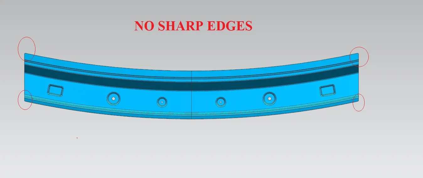
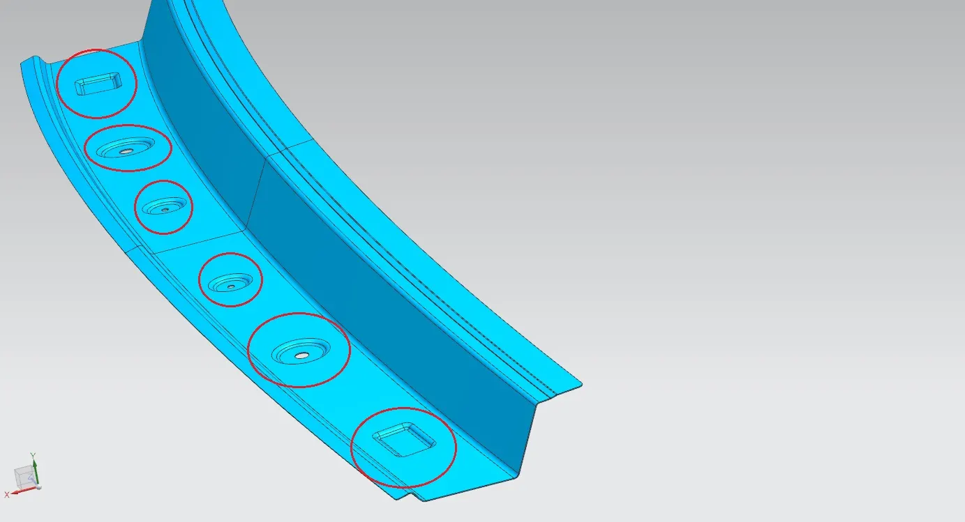
I provided Some embosses for the extra strength for the front roof rail.We giving embosses for the strength to the component.
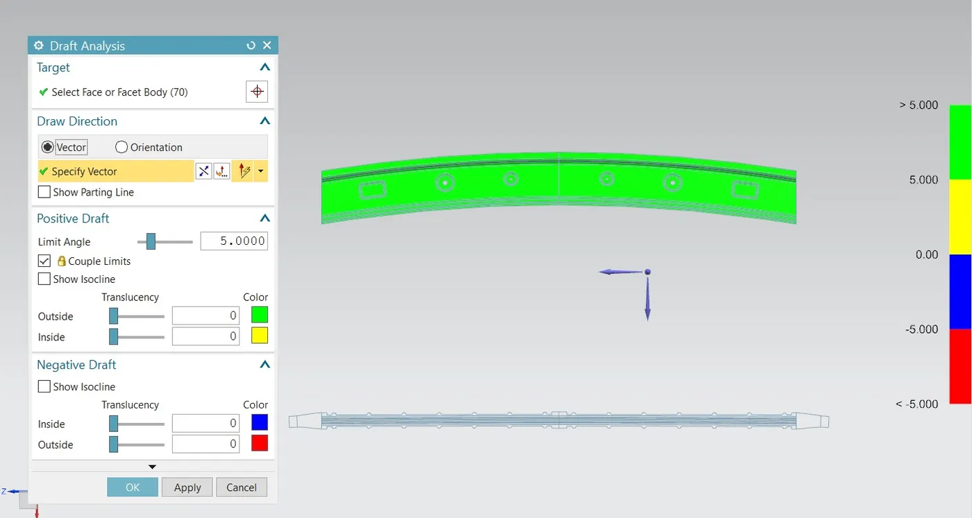
DRAFT ANALYSIS
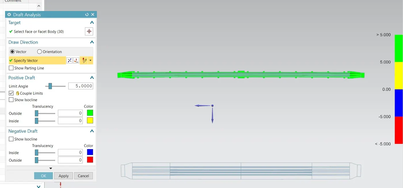
Draft analysis is a method of checking the draft angle on various faces of a part with a particular direction.
Draft Analysis command enables you to detect if the part you drafted will be easily removed. This type of analysis is performed based on color ranges identifying zones on the analyzed element where the deviation from the draft direction at any point, corresponds to specified values.
WHY We Do Draft Analysis
Every part like sheet metal parts which are generated from a Press Tool or some forming tools, may be the plastic parts which generally come out from the plastic moulds and maybe the casting parts, all such kind of parts required some drafted face on the surfaces which are parallel to the tooling direction. If we don't provide drafts on the surface then it will stick to the mould surface and whenever the mould is in motion they will destroy the surfaces or also reduced the finishing of surfaces.
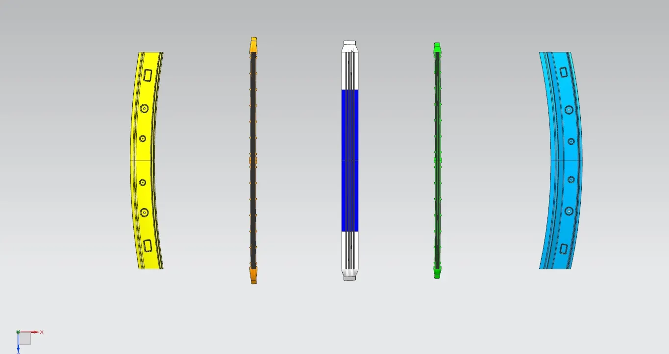
Front ROOF RAIL
Bow1 ROOF RAIL
Central ROOF RAIL
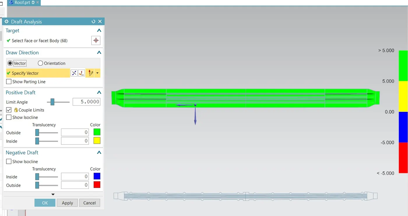
Bow2 ROOF RAIL
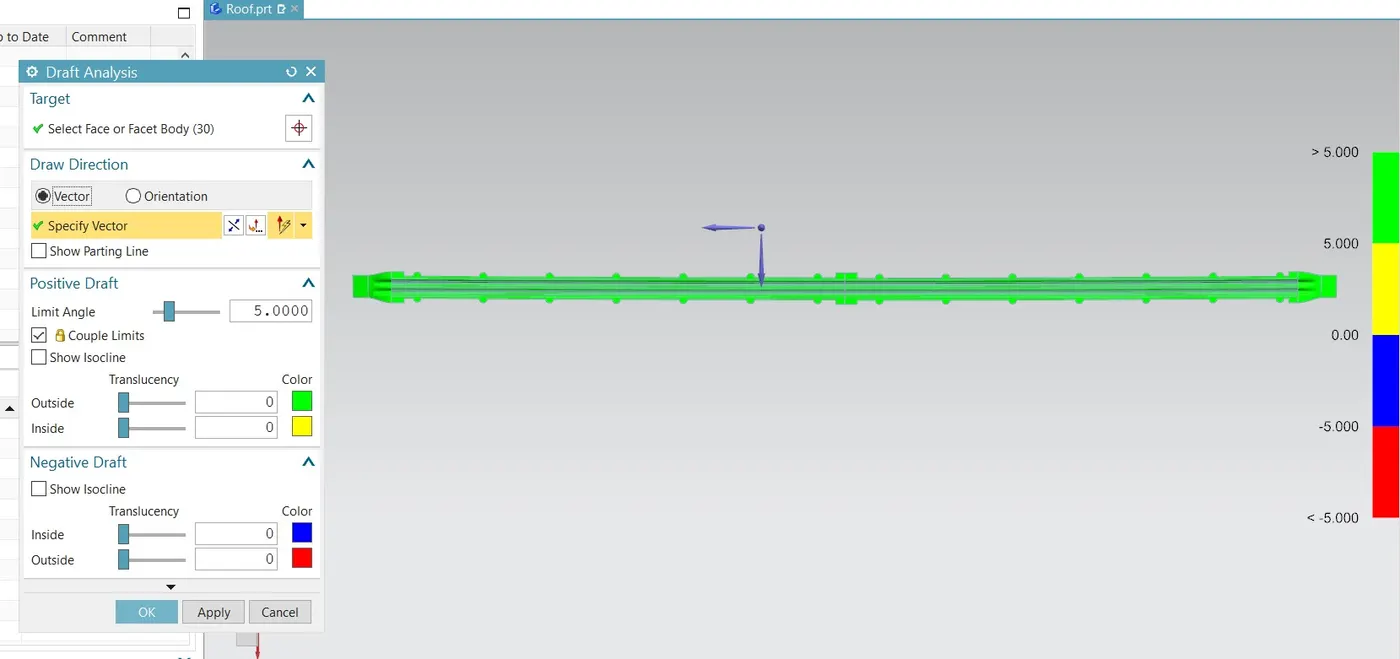
Rear ROOF RAIL
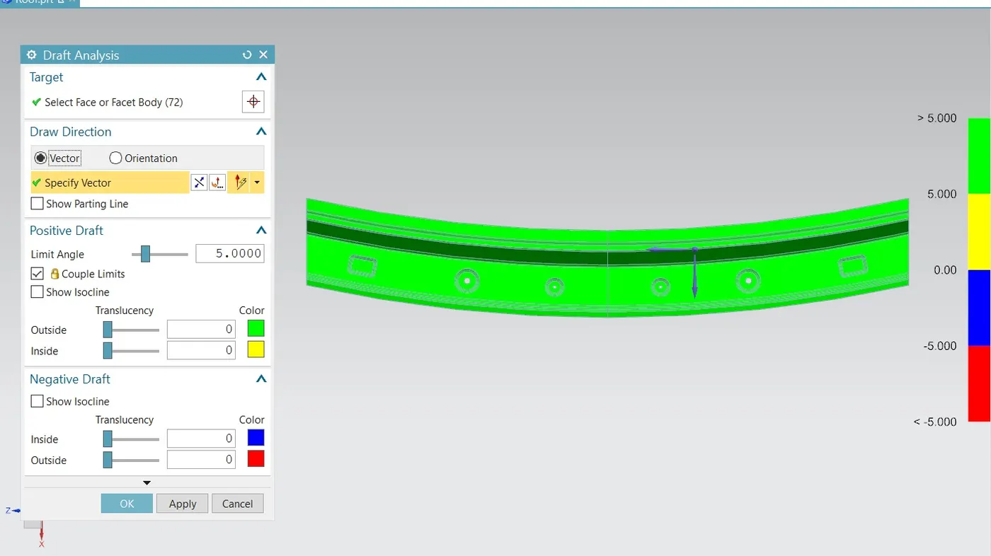
OUTER ROOF
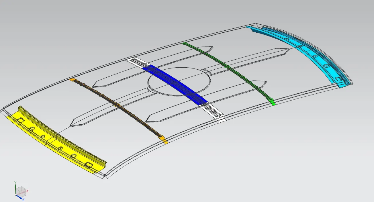
SECTION MODULUS AND THE MOMENT OF INTERIA VALUES FOR BOW,FR,RR ROOFS
Front Roof Rail MOI
Below picture refers that the Front roof rail momnet of interia values.
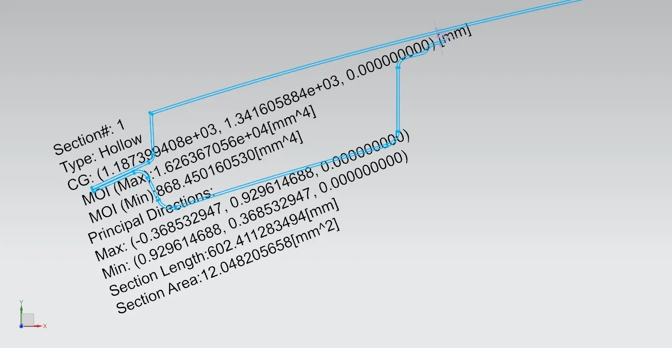
Bow 1 Roof Rail MOI
Below picture refers that the Bow 1 Roof Rail momnet of interia values.
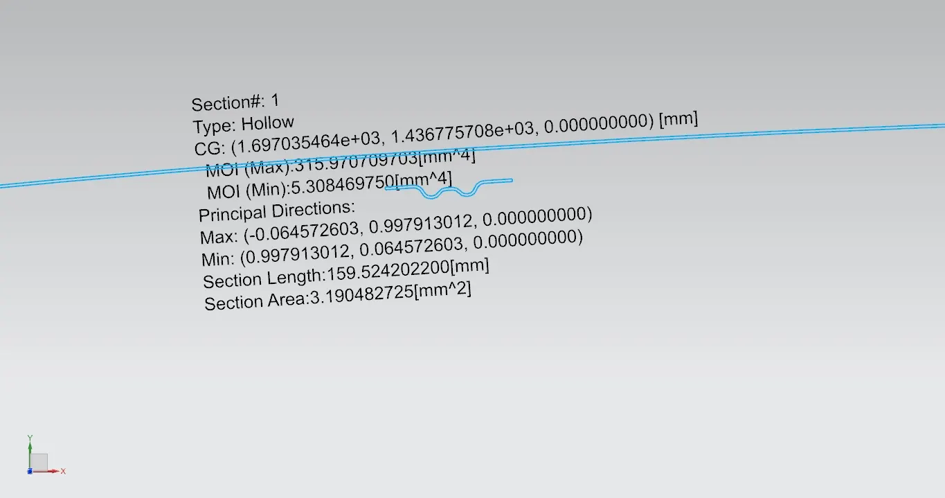
Central Roof Rail MOI
Below picture refers that the Central Roof Rail momnet of interia values.
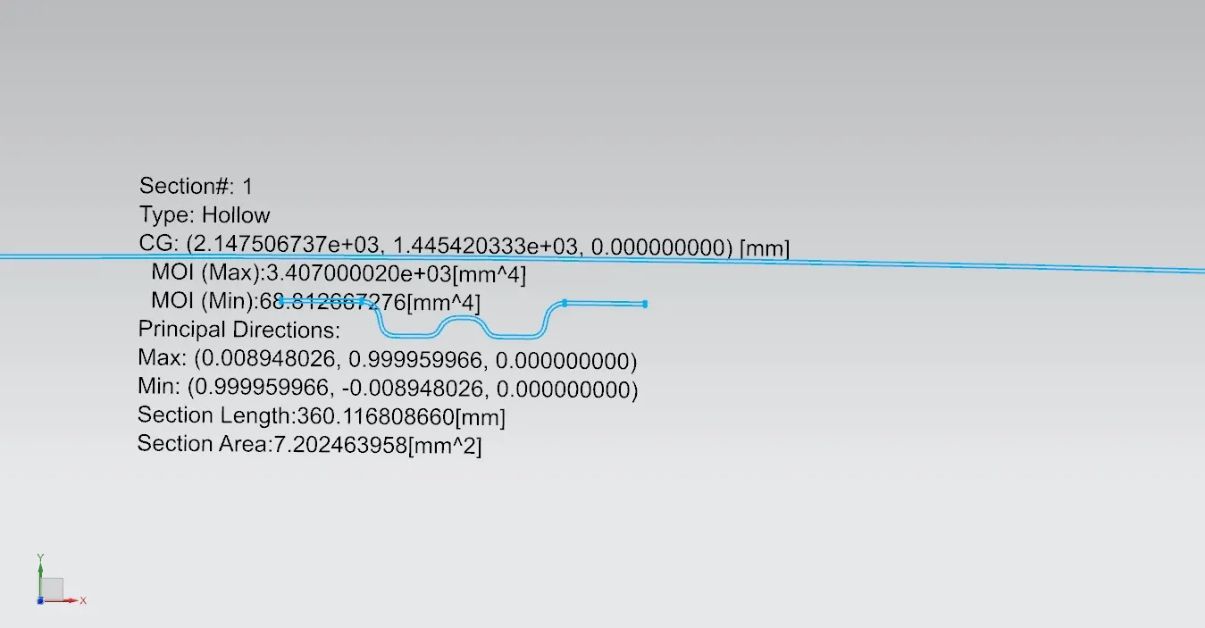
Bow 2 Roof Rail MOI
Below picture refers that the Bow 2 Roof Rail momnet of interia values.
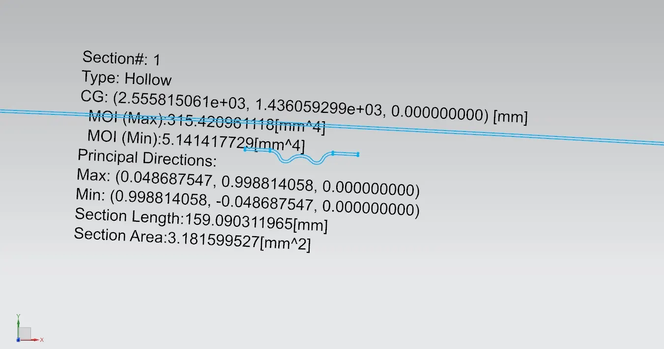
Rear Roof Rail MOI
Below picture refers that the Rear Roof Rail momnet of interia values.
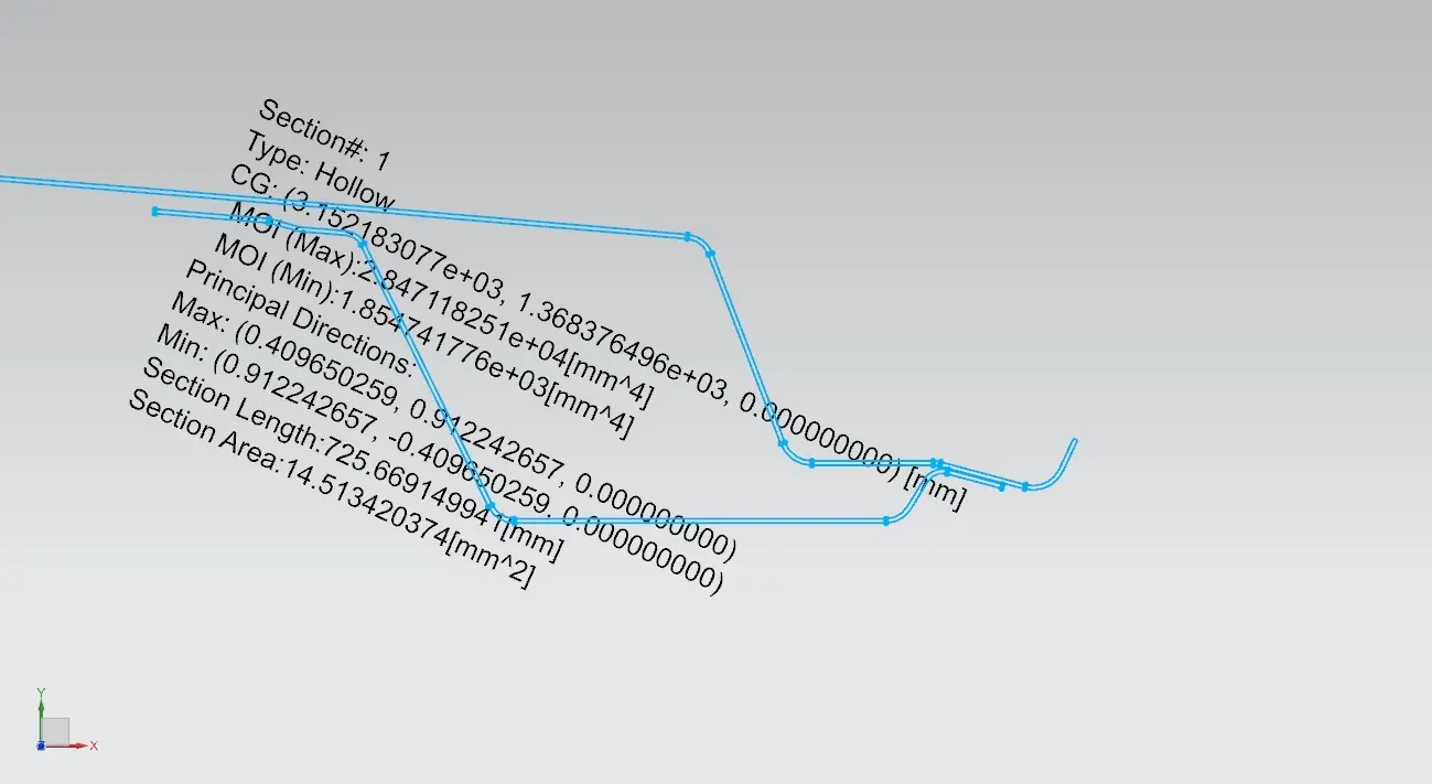
ROOF ANALYSIS
They are two types of conditions that the designed roof needs to pass.
Before giving to the CAE team,Designers usually check with the below formulas for Roof design is OK or NG.
1.Heat Distortion Criteria
2.Snowed Load Criteria
1.HEAT DISTORTION CRITERIA
If the curvature of the styling part is good no need of using BOW roofs to the Car
Bow – roof prediction Formula
W = [1.73 x 10^(-3) x L] + [1.85 x 10^(-8) x (R^2)/t] + [ 1.10x10^(-3) x l] - 2.68
Judgement Condition : OK< 2.7> 3.1
Where
L = Roof Length in X-Direction[mm](Roof dimension in 0-Y)
R = Roof curvature
R = 2(Rx*Ry)/(Rx+Ry)
Rx = X curvature
Ry = Y curvature
t = Roof plate thickness [mm]
l = Bow Roof Span [mm]
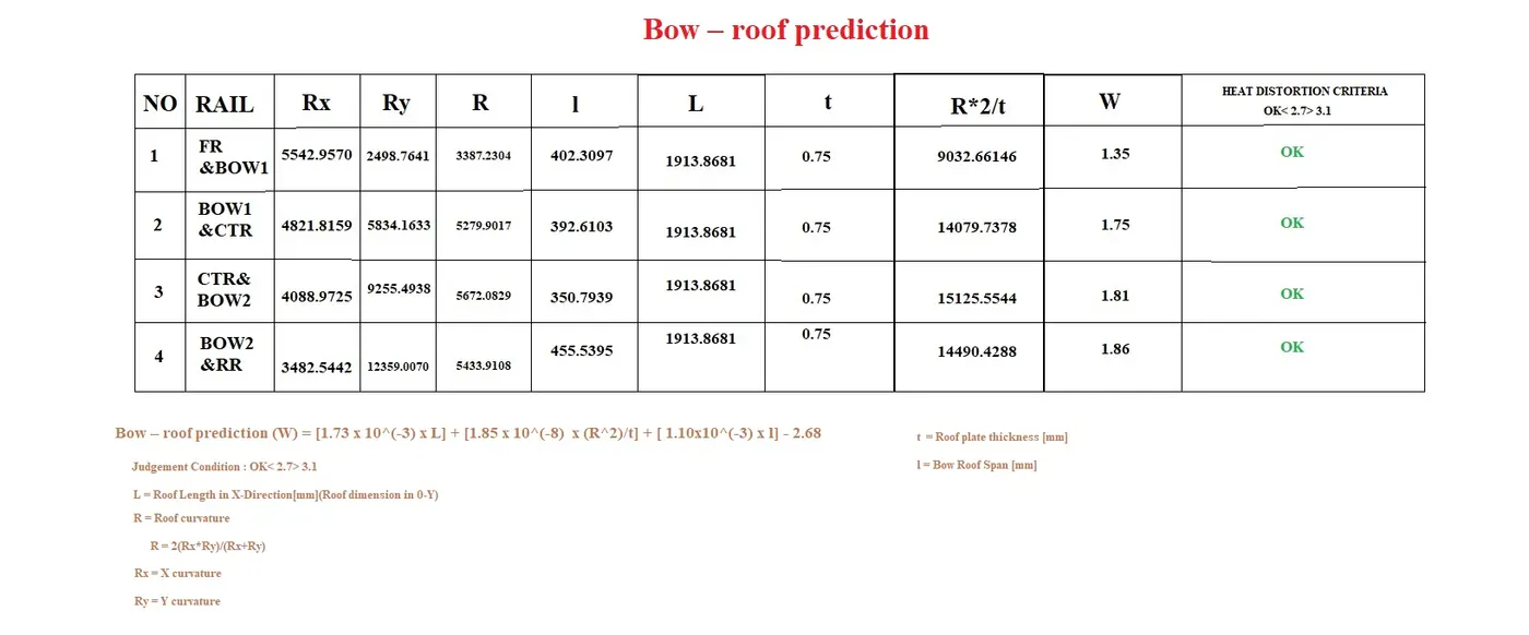
After calculations I got OK by this heat distortion formula so my FR,RR,BOW and CTR roofs are GOOD and also satisfied.
2.SNOWED LOAD CRITERIA
This formula is for snowed conditions,If our car is in kashmir or some other cold places there be minus celsius temperature.
If the below formula is for checking the snowed load criteria in desinged FR,RRCTR,BOW roofs,We must satisfy this formula.
Snow load Prediction formula
Qr = [Iy x t2] / [α x s x [(Rx + Ry)/2]2 x 10-8]
Note: The Qr value given over here is correct. There was a typo error in the formula given in the video.
Where
α = My x Lx2 x 10-12 , My = Y(Ly-Y)
Judgement condition = Qr ≥ 3.1
250 ≤ s ≤ 380
t = Roof plate thickness [mm]
Ly = Distance between the front and rear roof Rails on the Vehicle along with 0Y[mm]
Length of Roof panel with the center point between Roof rail Front /Rear as the reference point of the front and the rear.
Lx = Distance between the Left and Right end of the roof on the Roof BOW [mm]
Width of the roof panel exposed on the surface.
Y = Distance front Front Roof Rail to Roof BOW[mm]
s = Distance for which Roof BOW bears divided load [mm]
s = L1/2 + L2/2
Iy = Geometrical moment of inertia of Roof BOW (Y cross-section )[mm4]
Rx = Lateral direction curvature radius of roof panel Y cross-section on Roof BOW [mm]
Roof panel curvature Radius of the Length Lx in Front view
Ry = Longitudinal Direction curvature radius of the Roof panel X cross-section on Roof BOW [mm]
Roof panel X curvature radius of length s in Side view
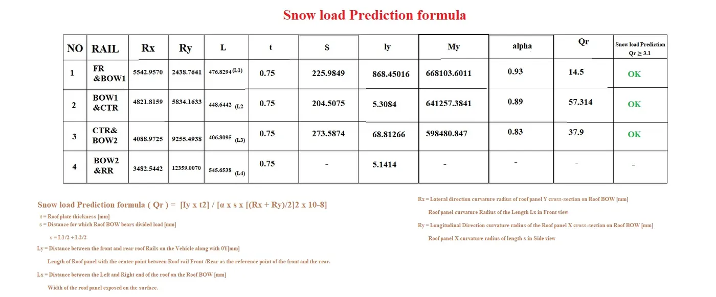
Hence i satisfied above snow load criteria and also Heat distortion criteria,above are the values i got From my design.
CONCLUSION
Hence,For the given Rood styling part,I designed Front,Rear,Bow1 and Bow 2,i did curvature study for the roof and calculations also.