BIW EXTERIOR TRIM : ROOF PANEL DESIGN
OBJECTIVE
The aim of this project is to model a Roof Panel of Car from the Roof Styling Surface. The Project report deals with the design of essential flanges and reinforcements followed by detailed study about draft analysis, Section Modulus Report. Finally, Roof Curvature Study is done to position those reinforcements to improve the strength of the Roof to withstand Snow load and Roof Crush.
DESIGN METHODOLGY
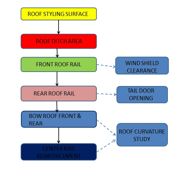
REPORT
ROOF PANEL
Roof is an integral part of BIW component and holds a major factor in weight reduction of the car and safety of the passengers in cabin. The styling of roof generally requires in depth analysis of different aspects
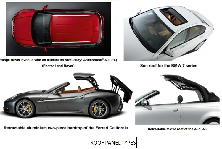
STYLING INPUT
The input is obtained as Styling Surface and is used to develop the engineering features
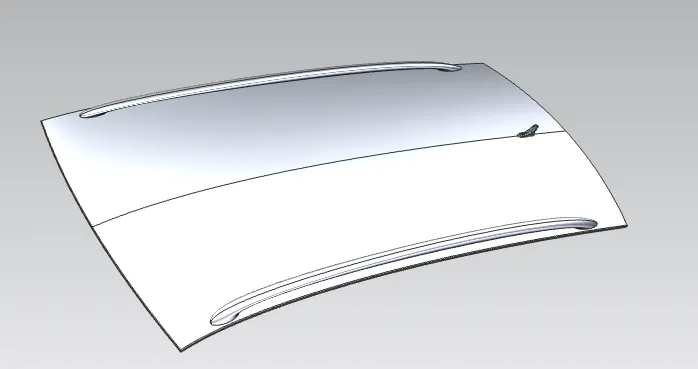
The Parts to be developed are
Roof Ditch Area
Front Roof Rail
Rear Roof Rail
Bow Roofs
Center Roof Reinforcement
DESIGN CONSIDERATIONS
ROOF DITCH AREA
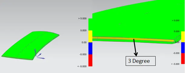
The Roof area is developed based on the Master Section and provided with Positive Draft Angle for all the flanges to have a feasible manufacturing.
The Opening angle condition determines the visibility criteria of the passenger hence the flange on frontal Roof area is set to 3 degrees
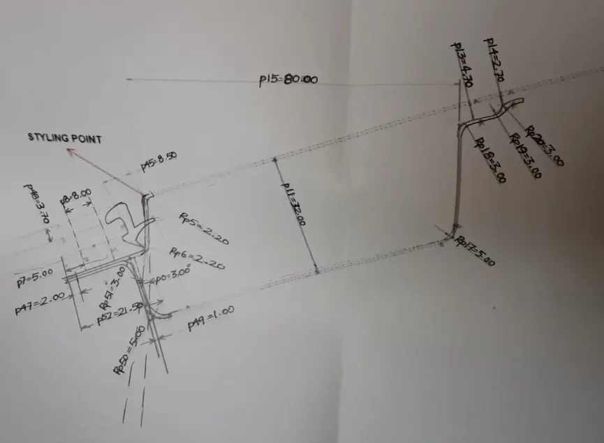
The Rear Roof Area is designed for Back Door Opening to accommodate backdoor components
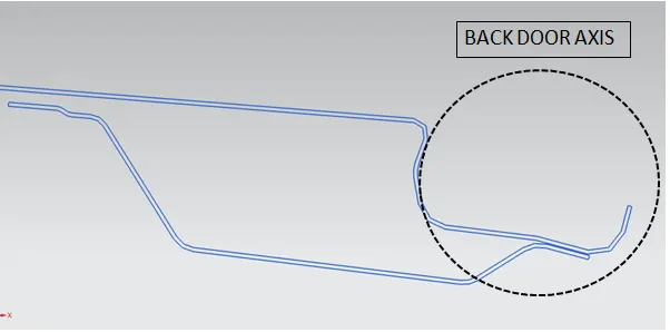
The Tail gate opening Axis is shown above
For Manufacturing Feasibility,
1) Corner Relief are porvide along the bend corners to avoid stress concentration and better Tool Path
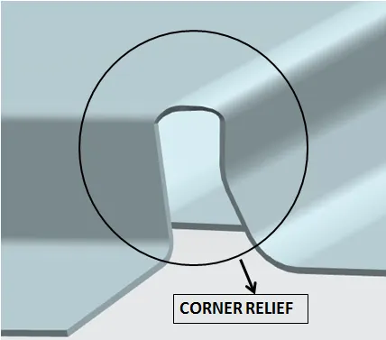
2) Draft Analysis is done to avoid Negative Draft which adds complexity to produce parts
Draft Analysis Report For frontal area of Roof is shown below
Draft Analysis Report for Rear Section of the Roof Ditch Area is shown below
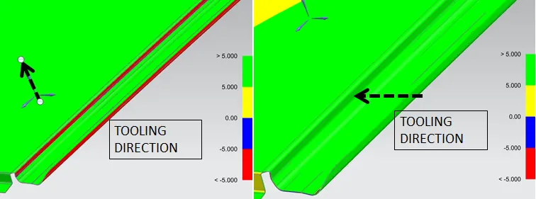
Thus the Rear Section involves a seperate tooling direction apart from the Main Tooling
FRONT RAIL
The Front Roof Rail is designed to accommodate Wind Shield Glass with Rubbers Sealant hence a Frontal clearance of minimum 21 is provided.
The Opening angle condition determines the visibility criteria of the passenger and is set to 3 degrees and the depth of the Rail is restricted not beyond 32mm to provide tooling workability consideration and the distance of Front Rail is usually limited to 80mm to provide ample head room clearance.
Based on these considerations the Flanges are worked around with a thickness of 0.75mm.
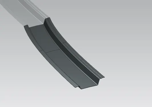
Positive Draft Angle condition is maintained for all the law extensions and Draft Analysis is done to ensure the above condition
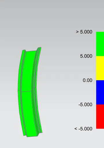
Draft Analysis Report For Front Roof Rail is shown below
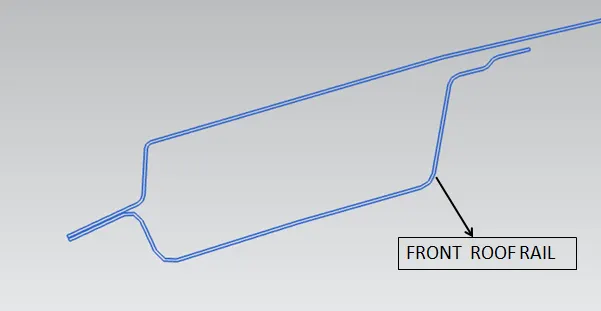
The Master Section and Section modulus report for Frontal Rail are given below
REAR ROOF RAIL
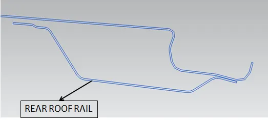
The Rear Roof Rail is designed and positioned based on the Roof Area and the thickness of the part is 0.75mm and has a close tolerance at the start and end of the part to achieve the fixation of Roof Rail to the Roof Area
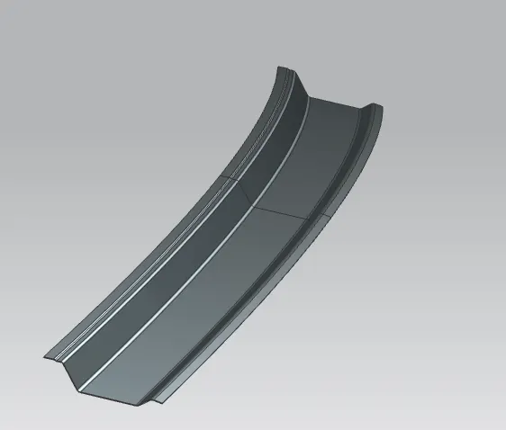
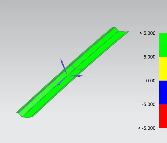
The Master Section data and Draft Analysis Report are attached below
CENTER ROOF
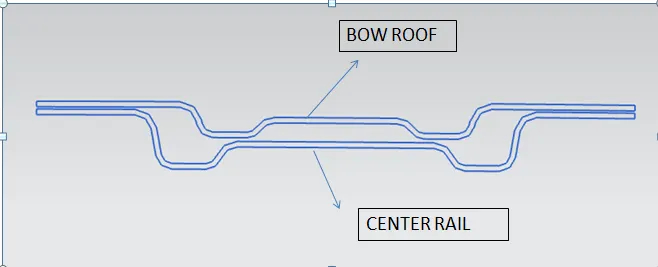
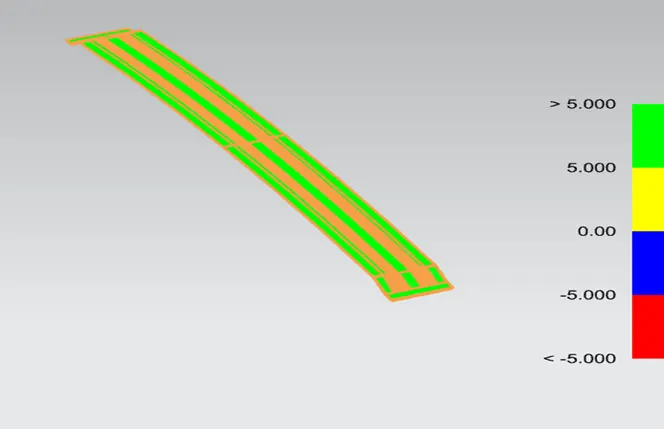
The model has Center Rail Reinforcement that provides strength to the Roof and the also houses other mounting features. This model has Center Roof reinforcement along with the bow roof.
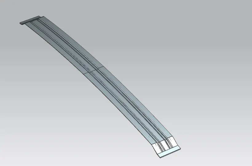
The Position of the reinforcements are based on the Roof Curvature study. The Structure is mounted with a spot weld and hence has very tight tolerance with the roof. Master Section and Draft analysis report are attached below
BOW ROOF
The Model has two Bow Roof one between the Front Rail and Center Roof Rail and other between the Center Roof Rail and Rear Roof Rail respectively.
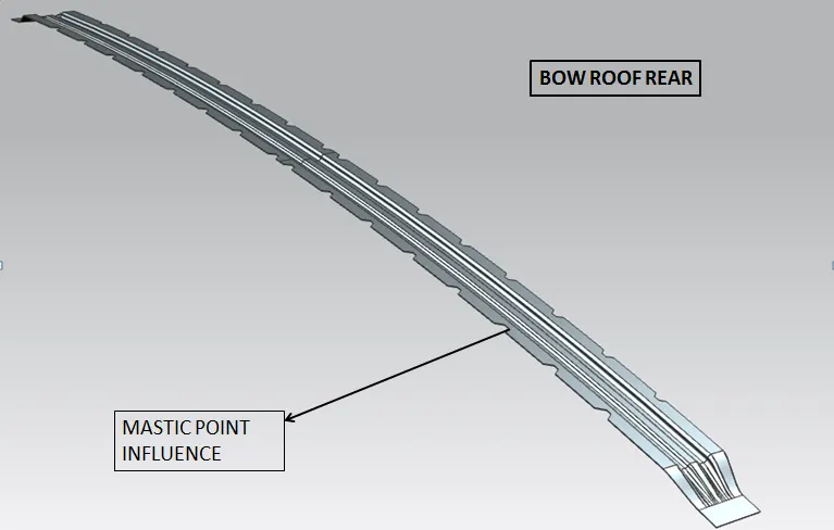
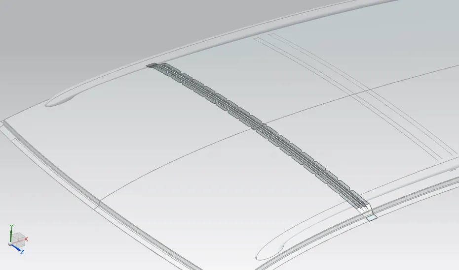
The Bow Roof is provided to withstand the load conditions under different situations. The Bow roof is mounted with Mastic Sealants and the mastic Influence increases the strength of the component.
ROOF CURVATURE STUDY
This is a vital process to determine the positioning of the Reinforcements and to analyze the roof before Crash Test. This Study is determined for
- Heat Distortion
- Snow Load Criteria
- Roof Crush Test
The study involves calculation of Radius of Curvature at different set of points to construe Flat Surfaces and also to pass the above conditions. The Other Factors such as Moment of Inertia, Cross Section dimensions of X and Y Sections and span length between two reinforcements
HEAT DISTORTION TEST
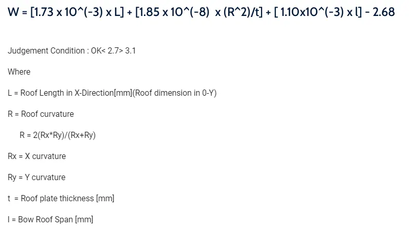
Based on the above formula the sectional points are taken at different positions of the Roof to calculate the above parameters
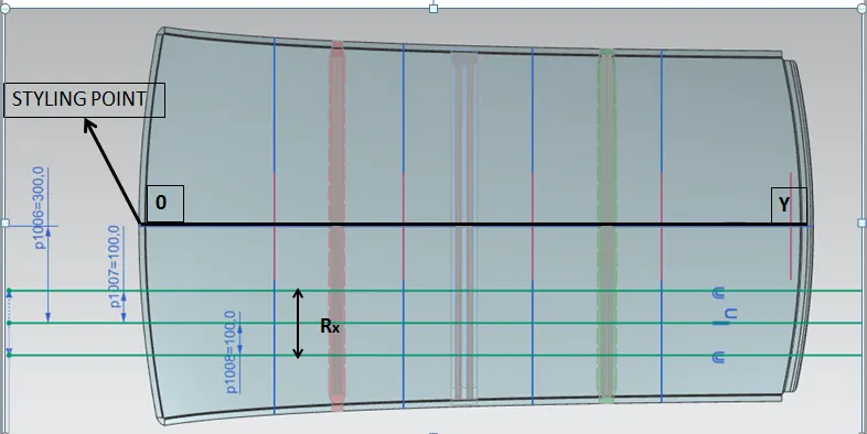
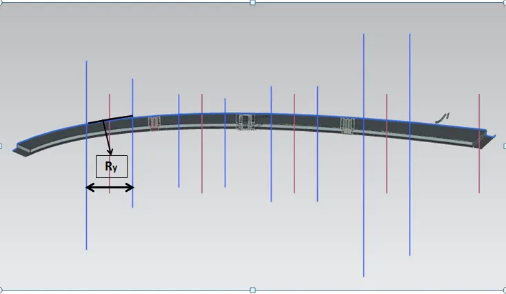

From the Table it is observed that the value of W is within the limit of 2.7
Hence the Roof will pass the Heat Distortion Test
SNOW LOAD CRITERIA
The Roof forms dent during the snow conditions due to heavy impact loading of Snow concentrated on the roof.
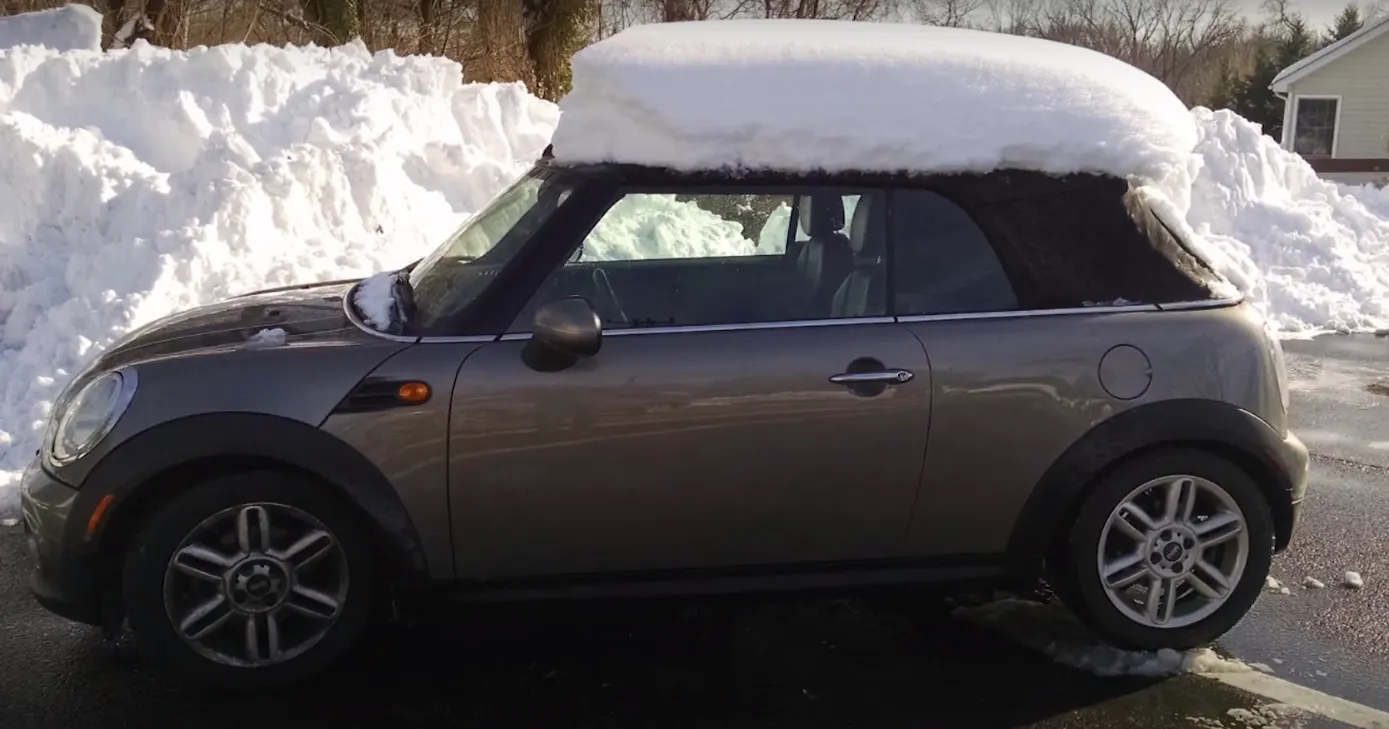
Hence it is required to judge the Roof Panel based on these parameters mentioned below
Qr = [Iy x t2] / [α x s x [(Rx + Ry)/2]2 x 10-8]
Where,
α = My x Lx2 x 10-12 , My = Y(Ly-Y)
Judgement condition = Qr ≥ 3.1
250 ≤ s ≤ 380
t = Roof plate thickness [mm]
Ly = Distance between the front and rear roof Rails on the Vehicle along with 0Y[mm]
Length of Roof panel with the center point between Roof rail Front /Rear as the reference point of the front and the rear.
Lx = Distance between the Left and Right end of the roof on the Roof BOW [mm]
Width of the roof panel exposed on the surface.
Y = Distance front Front Roof Rail to Roof BOW[mm]
s = Distance for which Roof BOW bears divided load [mm]
s = L1/2 + L2/2
Iy = Geometrical moment of inertia of Roof BOW (Y cross-section )[mm4]
Rx = Lateral direction curvature radius of roof panel Y cross-section on Roof BOW [mm]
Roof panel curvature Radius of the Length Lx in Front view
Ry = Longitudinal Direction curvature radius of the Roof panel X cross-section on Roof BOW [mm]
Roof panel X curvature radius of length s in Side view
Based on the Above Parameters the values are ploted and the table is shown below

Thus the Roof will bear the Snow Condition Test.
RESULT
Thus from the above table the Heat Distortion Study value W is well within the permissible range (2.7) and for the Snow Load Test the Qr Values are greater than 3.1.
Draft Analysis is done for the components shows that parts are feasible to manufacture and for Roof Rail a second set of operation is done on the side
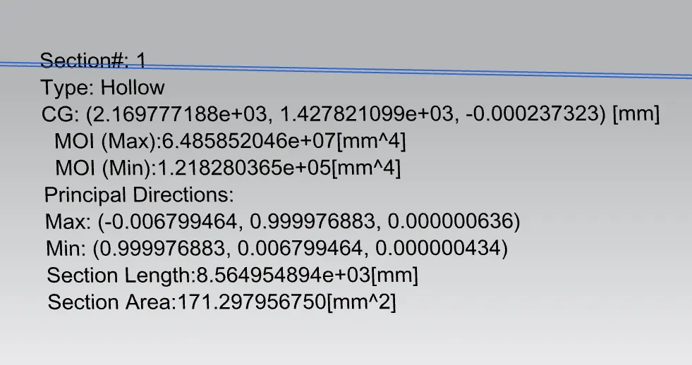
Finally the Section Modulus report is also taken to analyse the moment of Intertia along Y Cross Section
If the Curvature Study yields negative results ie less than the specified values then the Styling team is notified for Surface curvature Improvement and sometimes emboss are provided on the guide rails to improve the strength
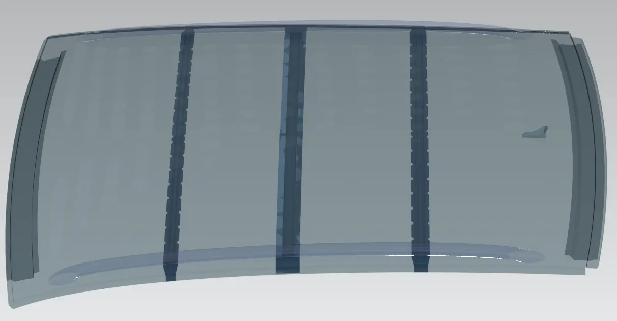
The Bow Roof and Center Rail Positions are shown below
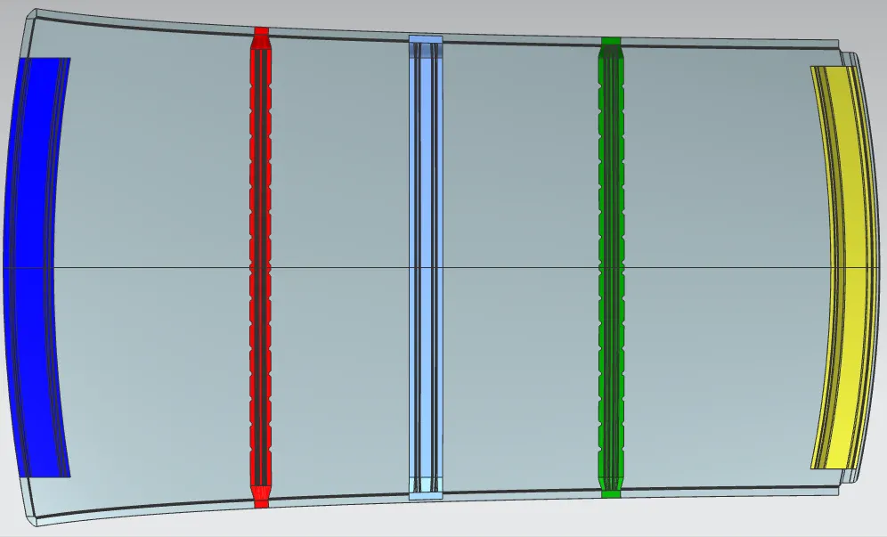
The Sectional Modulus Report for 0-Y Cross Sectional View is shown below
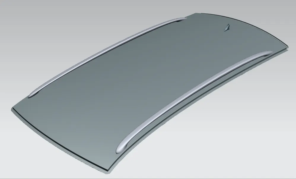
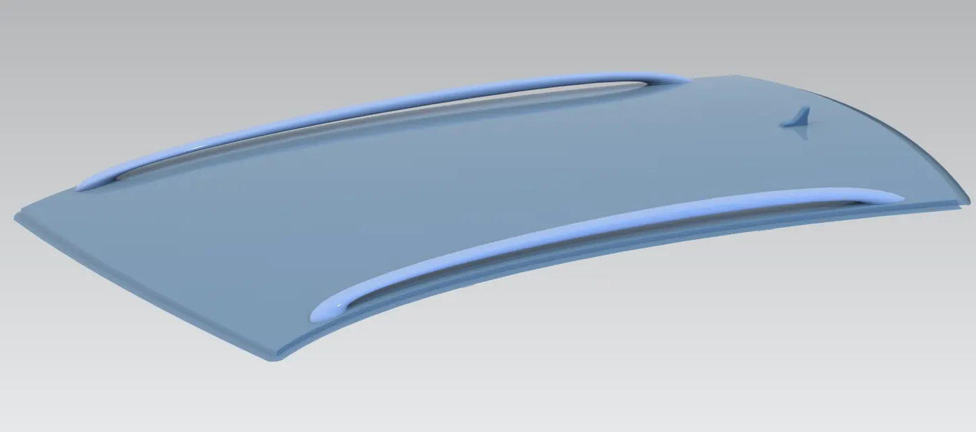
Rendered View of BIW ROOF
CONCLUSION
Thus based on the input styling surface, essential flanges and reinforcements are developed by providing appropriate dimension
Draft analysis and section modulus report on the 0-Y section is also analyzed and provided in the report
Detailed curvature study on the roof is done to determine the position of the Bow-roof.