Automobile Roof Design and Curvature Study of Roof
AUTOMOBILE ROOF DESIGN AND VARIOUS ANALYTICAL CONSIDERATION FOR MODELING
INTRODUCTION
ROOF
An automobile roof or car top is the portion of an automobile that sits above the passenger compartment, protecting the vehicle occupants from sun, wind, rain, and other external elements. Because the earliest automobiles were designed in an era of horse-drawn carriages, early automobile roofs used similar materials and designs
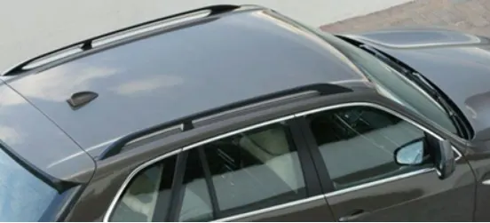
Now In this project, I am going to design and model an automobile roof with the help of some input data’s like master section of roof rails provided.
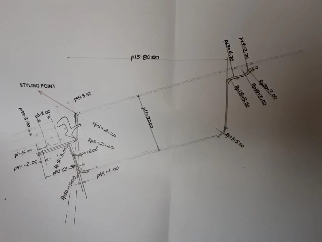
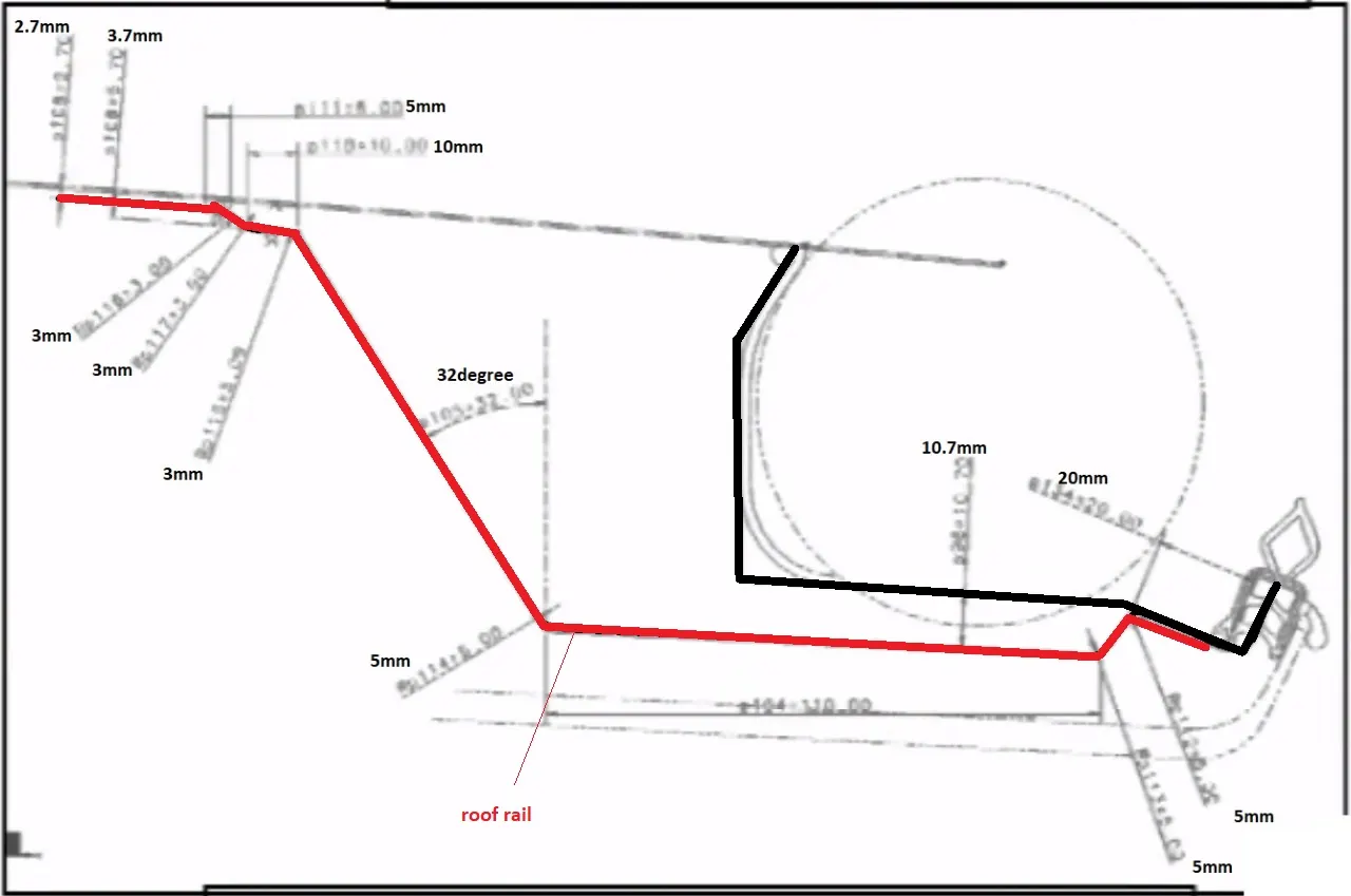
Front rail master section Back rail master section
By doing some research on these master sections and some videos I have come to know that, a single component does not specify or completes a roof, in a fully designed and modelled roof there should be some roof rails to support and protect the passengers inside the car and to withstand some amount of force which are,
- Outer panel
- Front Roof Rail
- Bow roof Rail (minimum 2 required)
- Centre Roof Rail with reinforcement
- Rear Roof Rail
DESIGN OF ROOF
- Outer panel
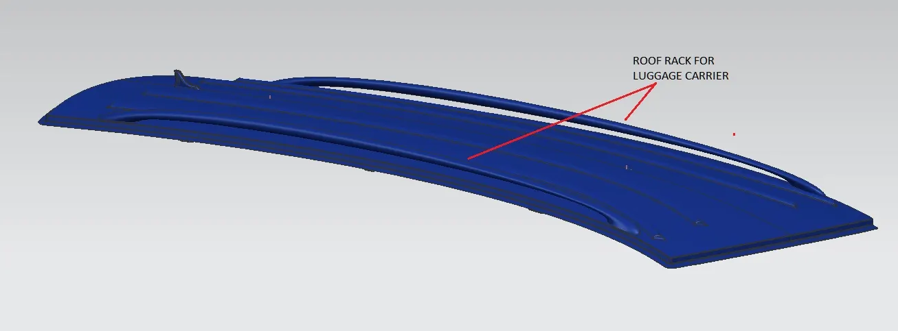
An outer panel is the outermost sheet metal of the roof in which there are aerodynamic cut-outs or sunroof cut-outs or etc. And there can be some fixtures or carriages to carry luggage on top of the car.
The thickness of the sheet metal of the outer panel should be around 0.75 mm and the flange area for the ditch should be minimum 15 mm.
Material – SP121AQ (Cold Rolled Mild Steel)
- Front roof rail
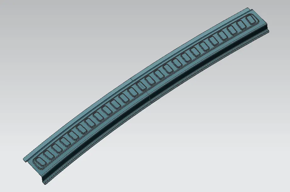
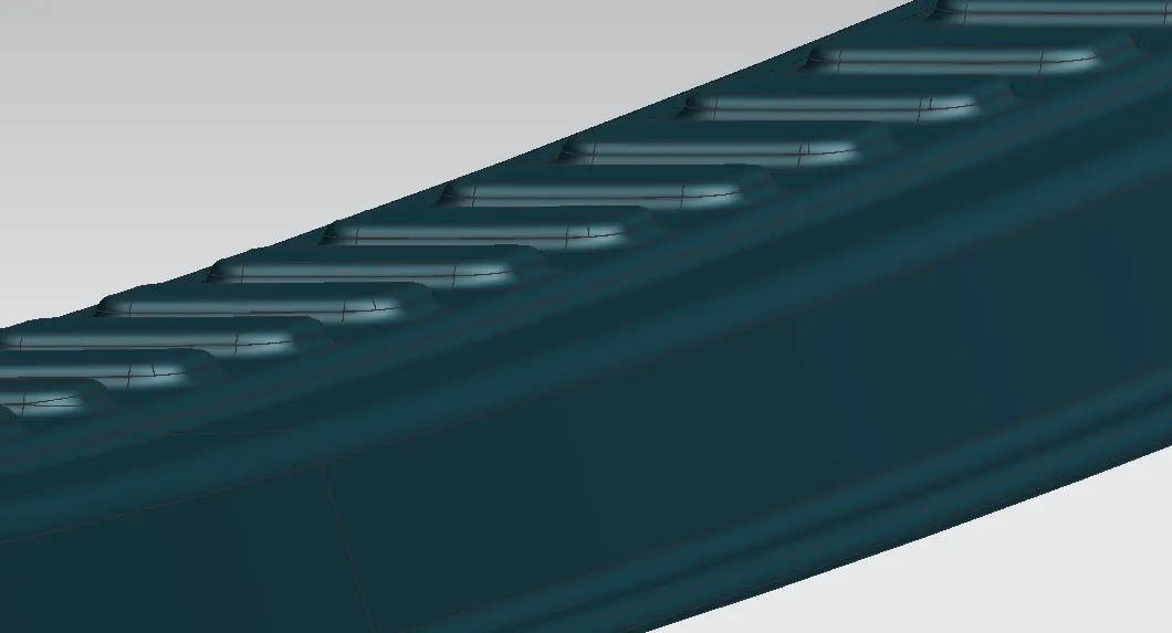
A front roof rail is a reinforcement placed on the front section of the roof. This reinforcement connects with side sections of the car and it also attaches with the front windshield of the car. With the available master section of the front rail. To increase the strengthens an emboss operation is also performed while modelling.
A model is designed with the following specifications-
Material – SP783AJQ (Terrace Zinc Galvanizing)
Thickness – 0.75 mm
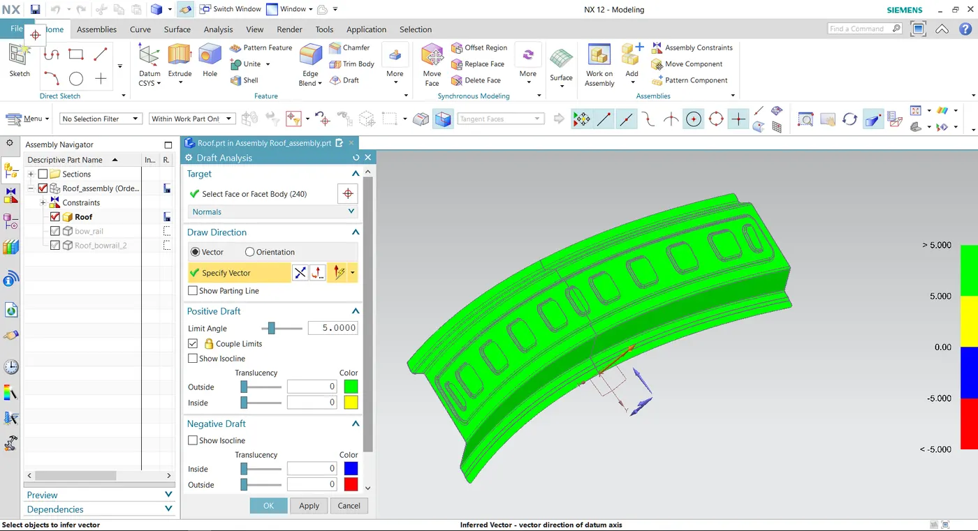
Draft Analysis
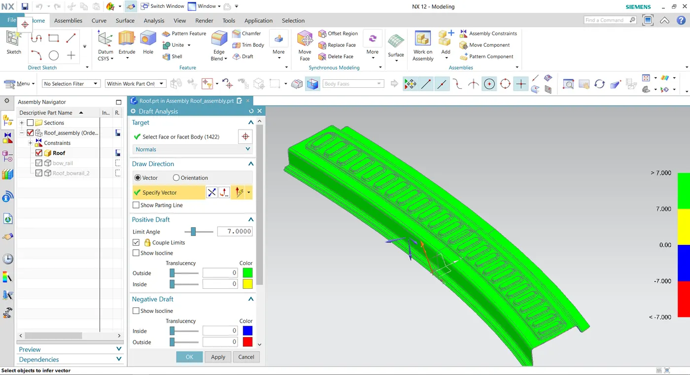
In the real-world application of manufacturing of sheet metals with some operations like hot and cold rolling, punching etc. The angle modelled in the CAD software for this component should be applicable for the real-world manufacturing processes also.
So, in the CAD software, some analysis can be made to precheck the operations that can be performed in Manufacturing industries. Draft analysis is one of the analyses that check the angle between the components which are operated in sheet metals.
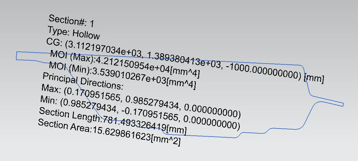
Section Inertia modulus Analysis
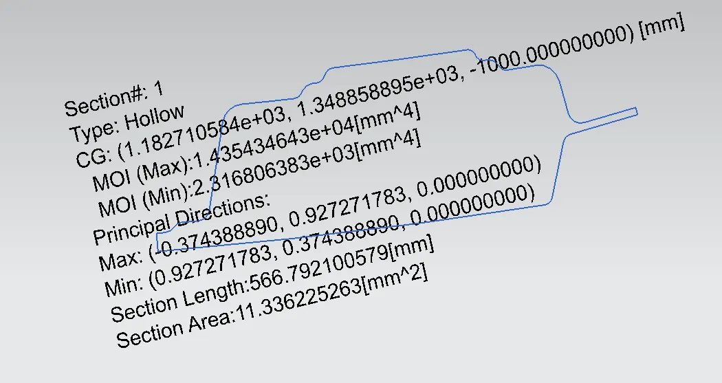
Section modulus is a geometric property for a given cross-section used in the design of beams or any component with flexural properties. Other geometric properties used in the design include an area for tension and shear, the radius of gyration for compression, and moment of inertia and polar moment of inertia for stiffness.
So, for the section of the front roof rail component a section inertia modulus analysis made to check the elastic properties or the deformation properties on the component.
- Bow roof rail (front)
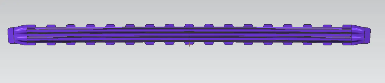
The front area for the bow roof rail is placed between front roof rail and centre roof rail reinforcements. This component main purpose is to strengthen the flattest surface on the roof available. so, wherever there is a flat surface on the roof rail reinforcement can be introduced. This bore roof rail front is fixed with both sides of the car.
Material – SP121BQ (Cold rolled steel coil)
Thickness – 0.75 mm
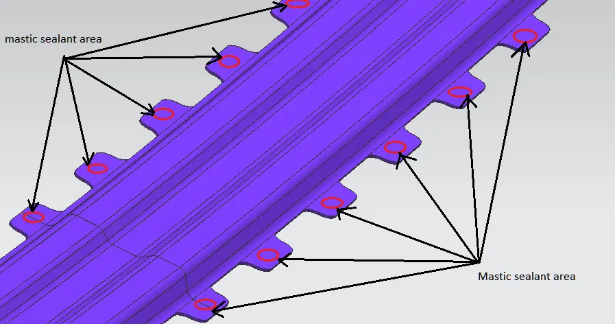
Mastic Sealant area
Mastic area is the area where the mastic sealant is applied to Unite the outer panel and the ball roof. If we do weld to combine both these components it may cause the overall visual and mechanical properties on the roof.
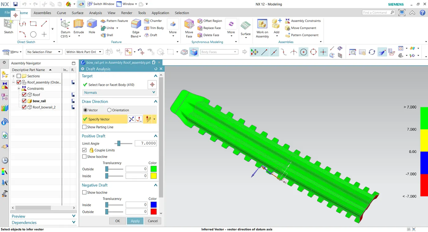
Draft Analysis
In the real-world application of manufacturing of sheet metals with some operations like hot and cold rolling, punching etc. The angle modelled in the CAD software for this component should be applicable for the real-world manufacturing processes also.
So, in the CAD software, some analysis can be made to precheck the operations that can be performed in Manufacturing industries. Draft analysis is one of the analyses that check the angle between the components which are operated in sheet metals.
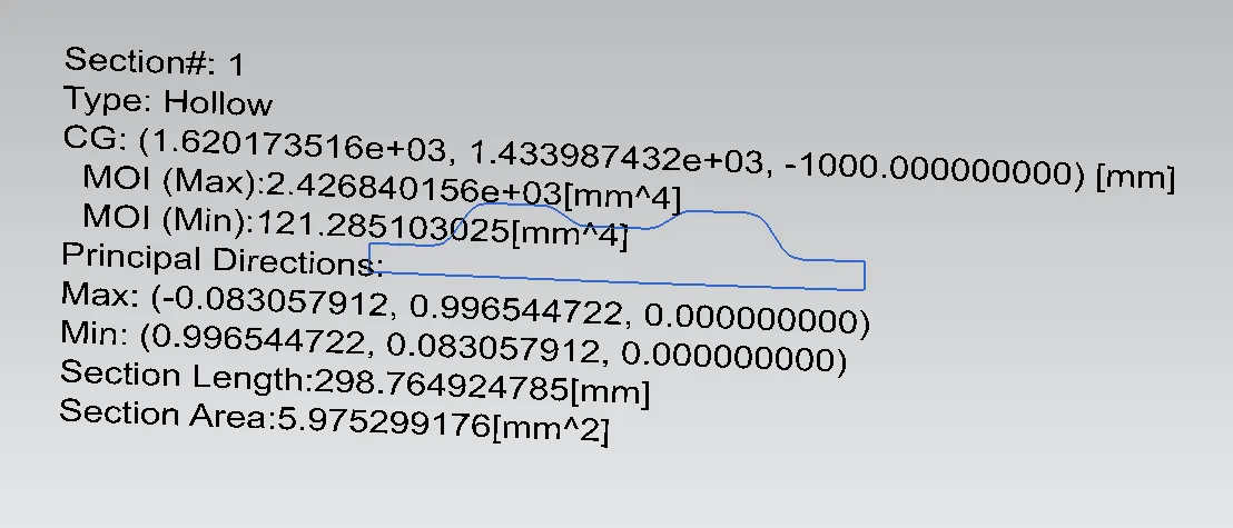
Section Inertia modulus Analysis
Section modulus is a geometric property for a given cross-section used in the design of beams or any component with flexural properties. Other geometric properties used in the design include an area for tension and shear, the radius of gyration for compression, and moment of inertia and polar moment of inertia for stiffness.
So, for the section of the front roof rail component a section inertia modulus analysis made to check the elastic properties or the deformation properties on the component.
- Centre roof rail with reinforcement
This component is also one of the bow rails that protect the car and as well as also the passengers from the roll-over accident or test. This component has also some of the Properties that can be attached to this reinforcement centre rail Like clamp for the compartment inside or attaching a fan etc.
This particular roof rail is important because a roof’s flattest area can we identify at the centre so for this reinforcement, there should be some importance given to it. so that's why it has two reinforcement attached to the outer panel.
Material – SP153 – 980 PQ (Cold Rolled JIS Steel)
Thickness – 0.75 mm (both)
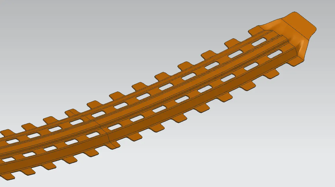
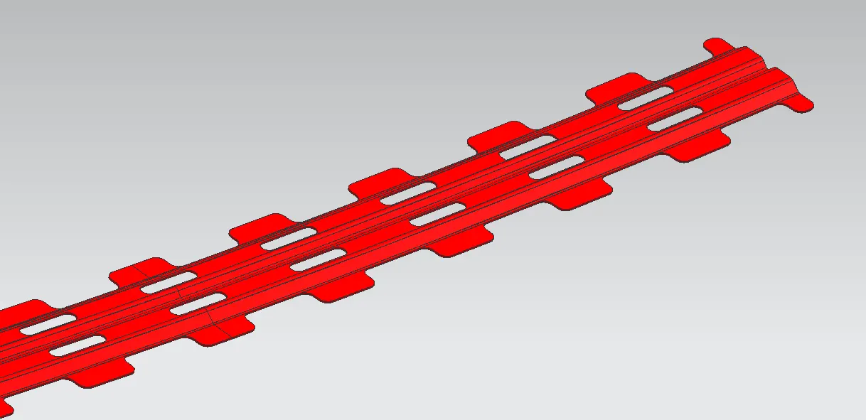
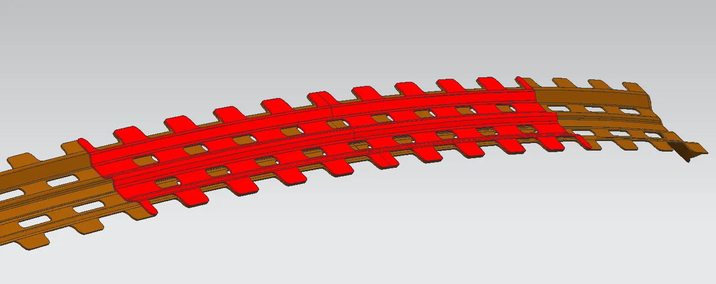
Weld spots
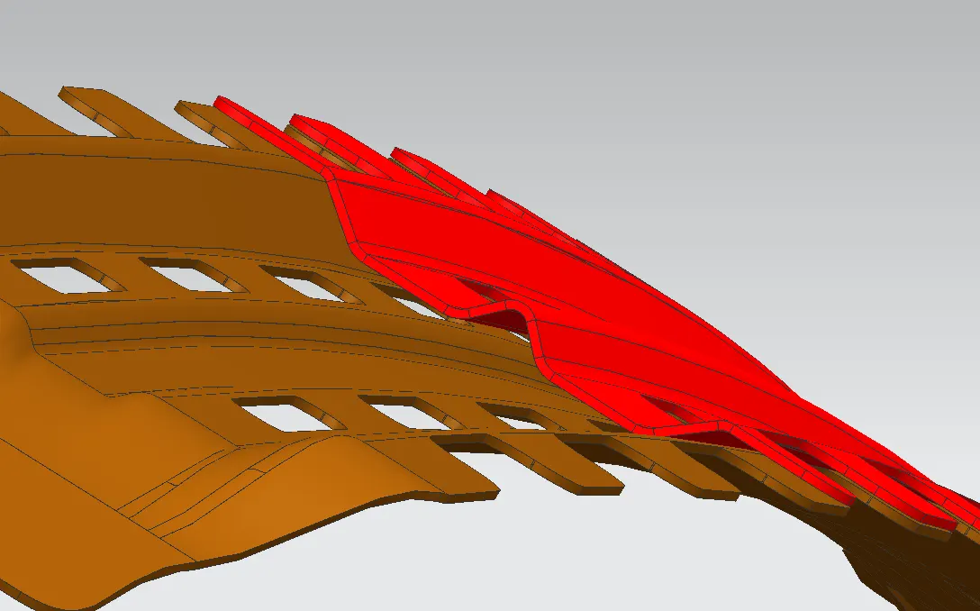
Draft Analysis
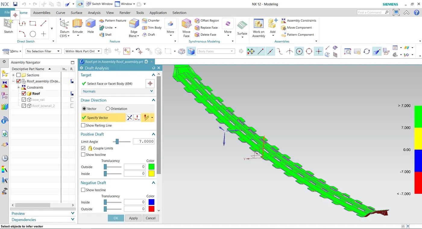
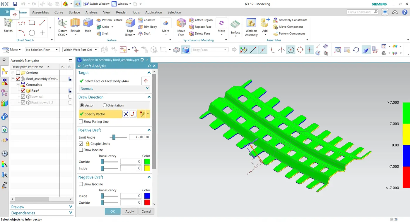
Section Inertia Modulus
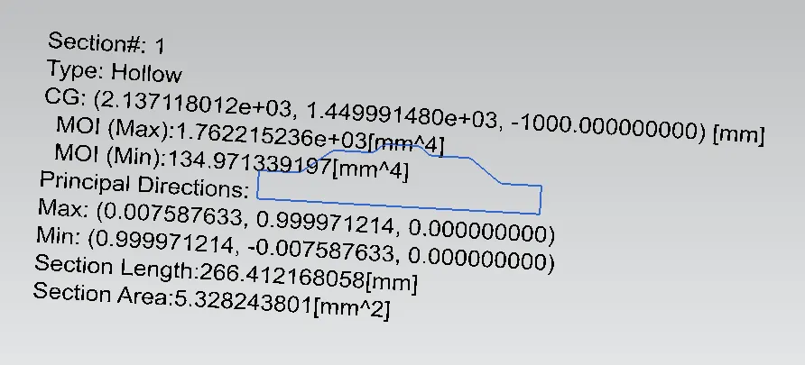
- Bow roof rail (back)
The back area for the bow roof rail is placed between back roof rail and centre roof rail reinforcements. This component main purpose is to strengthen the flattest surface on the roof available. so, wherever there is a flat surface on the roof rail reinforcement can be introduced. This bore roof rail front is fixed with both sides of the car.
Material – SP121BQ (Cold rolled steel coil)
Thickness – 0.75 mm
Draft analysis
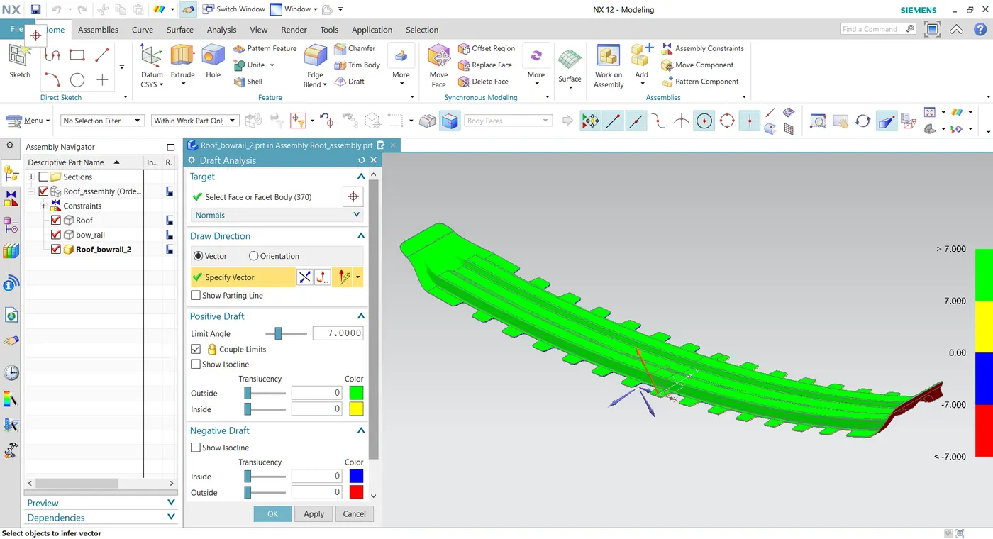
Section Inertia Analysis
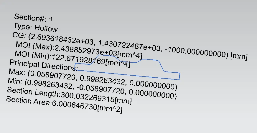
- Back roof rail
Back roof rail is placed on the rear side of the roof. This component or reinforcement has a different master section because this reinforcement has some properties like, to fix the back door to the roof a hinge is placed inside the reinforcement and the size of this reinforcement should be considered regarding with the head clearance area from rear seat compartment of the car.
Material – SP783AJQ (Terrace Zinc Galvanizing)
Thickness – 0.75 mm
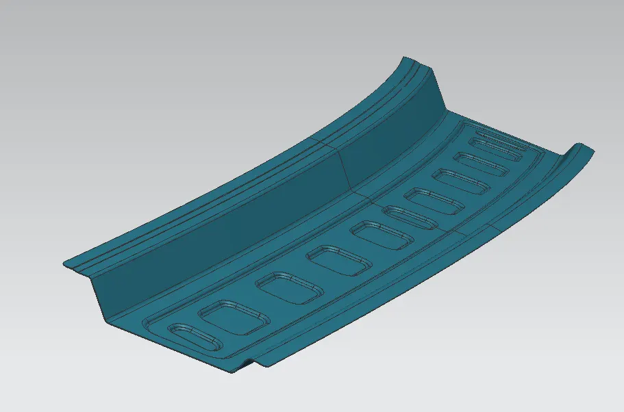
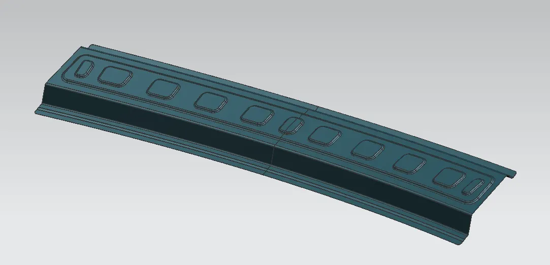
Draft Analysis
Section inertia modulus
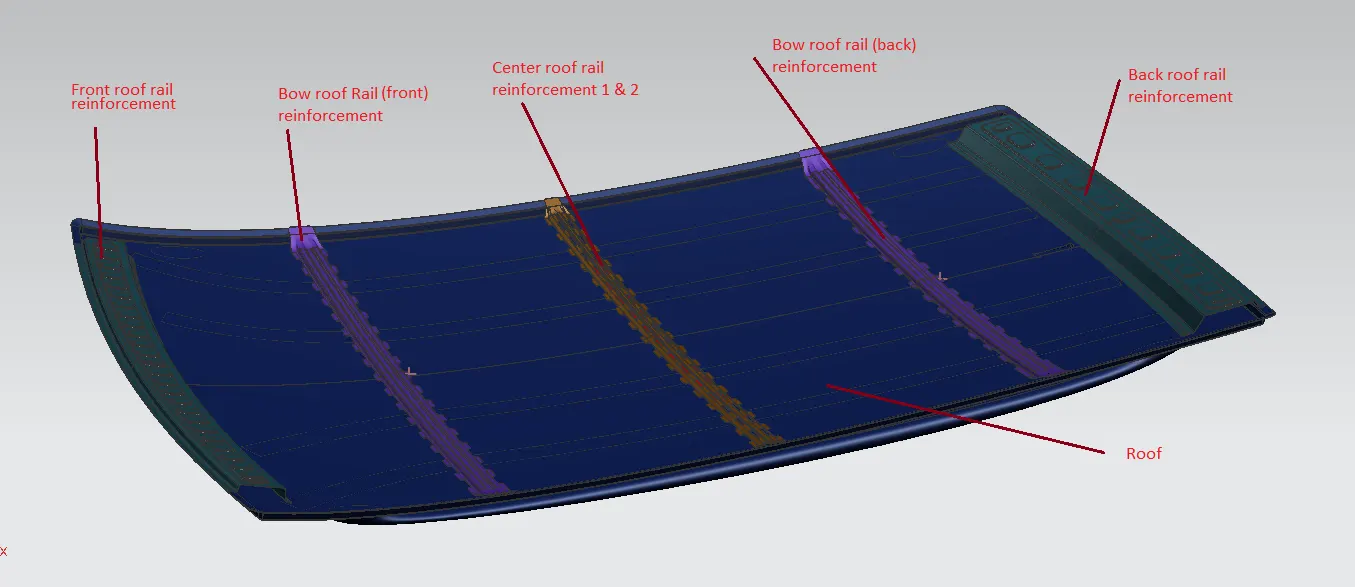
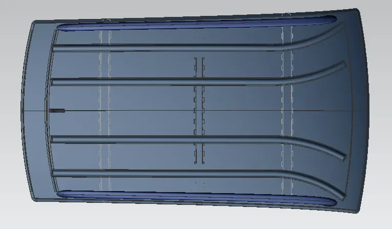
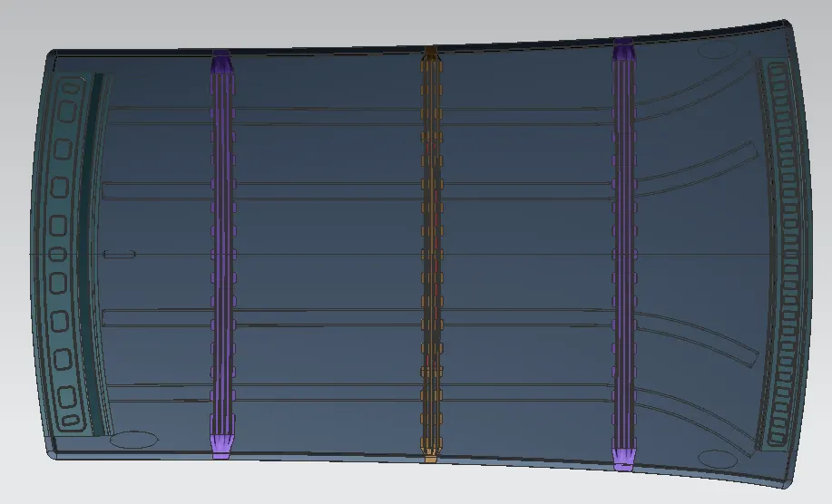
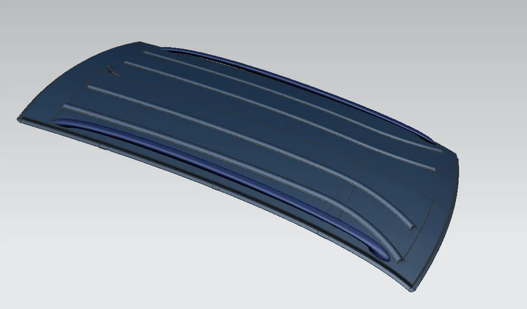
- Assembly of the roof with all reinforcements
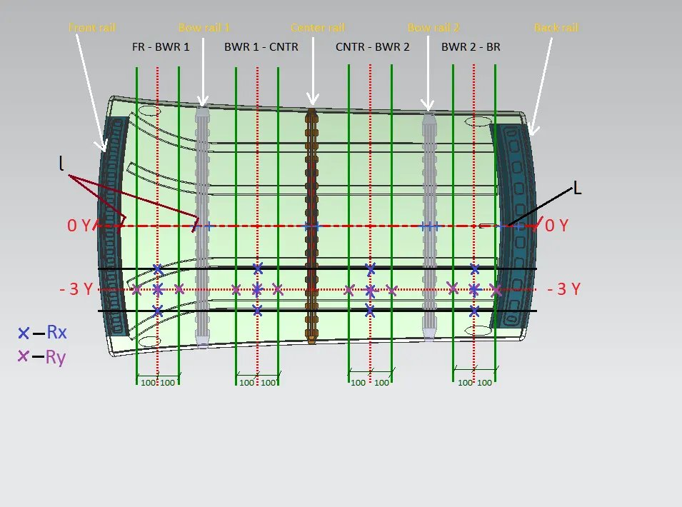
- CALCULATION OF BOW ROOF REINFORCEMENT PREDICTION
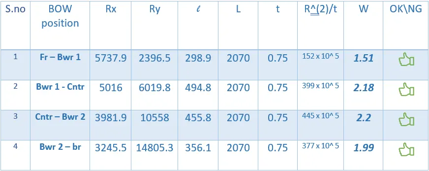
HEAT DISTORTION FORMULA
W = [1.73 x 10^ (-3) x L] + [1.85 x 10^ (-8) x (R^2)/t] + [ 1.10x10^ (-3) x l] - 2.68
Where
L = Roof Length in X-Direction[mm](Roof dimension in 0-Y)
R = Roof curvature
R = 2(Rx*Ry)/(Rx+Ry)
Rx = X curvature
Ry = Y curvature
t = Roof plate thickness [mm]
l = Bow Roof Span [mm]
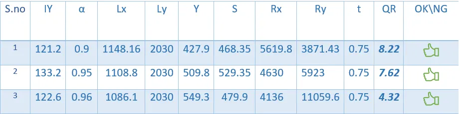
the curvature design criteria are OK if ‘W’ is: OK< 2.7> 3.1
Heat distortion Calculation table
Snow Load prediction Criteria
Qr = [Iy x t2] / [α x s x [(Rx + Ry)/2]2 x 10-8]
Where
α = My x Lx2 x 10-12 , My = Y(Ly-Y)
t = Roof plate thickness [mm]
Ly = Distance between the front and rear roof Rails on the Vehicle along with 0Y[mm]
Length of Roof panel with the centre point between Roof rail Front /Rear as the reference point of the front and the rear.
Lx = Distance between the Left and Right end of the roof on the Roof BOW [mm]
Width of the roof panel exposed on the surface.
Y = Distance front Front Roof Rail to Roof BOW[mm]
s = Distance for which Roof BOW bears divided load [mm]
s = L1/2 + L2/2
Iy = Geometrical moment of inertia of Roof BOW (Y cross-section )[mm4]
Rx = Lateral direction curvature radius of roof panel Y cross-section on Roof BOW [mm]
Roof panel curvature Radius of the Length Lx in Front view
Ry = Longitudinal Direction curvature radius of the Roof panel X cross-section on Roof BOW [mm]
Roof panel X curvature radius of length s in Side view
Judgement condition = Qr ≥ 3.1
250 ≤ s ≤ 380
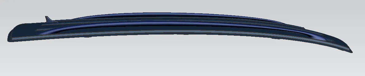
All model of the roof
- Alex AS VALUE FOR THE SNOWED CRITERIA DOESNOT SATISFIES THE JUDGEMENTAL CONDITION, THEN HOW THE Qr VALUE JUSTIFIED ?