Roof challenge
Aim:
Roof design using Catia V5 6R2020
Objective :
- Design the roof from the given styling surface and also create the center, rear roof rails.
- Create the reinforcements as center rail and bow roof rails.
- Study the roof design and validate the design by doing the heat distortion and snow load criteria.
- Perform the section modulus for the final component.
- Perform the draft analysis.
Introduction :
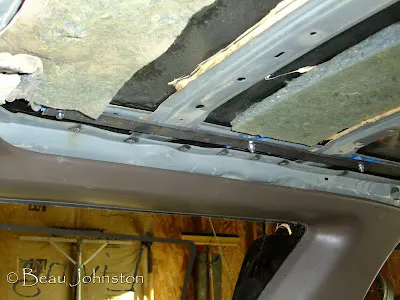
A roof structure for a vehicle body includes a roof opening defined by a pair of spaced-apart side rails, each having a flange extending inwardly and being vertically offset below the roof surface, and by front and rear headers, each having a flange defining a window opening. A roof panel assembly includes a roof outer panel and a pair of inverted hat-shaped reinforcement rails which underlie the outer side edges of the roof outer panel and include inwardly and outwardly directed legs abutting the underside of the roof outer panel.
The outermost portion of the side edges of the roof outer panel is hem flanged over the outwardly directed flanges of the reinforcement rails so that the roof outer panel and the reinforcement rails define the roof panel assembly. The roof outer panel has fore and aft end flanges which overlie the flanges of the front and rear headers and are spot welded thereto.
A bead of adhesive is placed on the inwardly extending flanges of the side rails and the roof panel assembly is lowered into the roof opening with the base wall of the reinforcement rails pressed onto the adhesive to attach the roof panel assembly to the vehicle body. The subsequent installation of the front and rear windows hides the spot welds.
Procedure:
Roof :
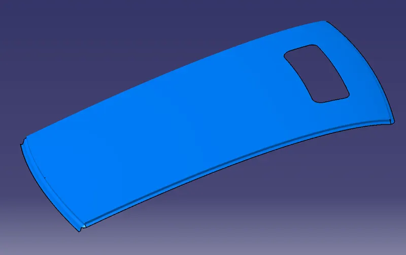
- The roof is the styling surface which is coupled with the rails and panels inside to make it a stronger and stiffer component.
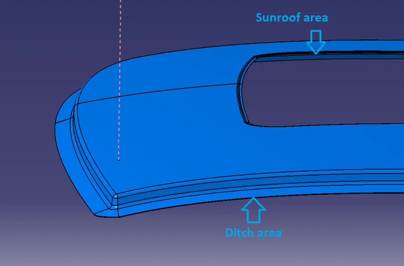
- The main area in the ditch is used to join the reinforcement components.
- The rail supports of the roof are attached to the Ditch Area using Spot welds since it is not a styling surface and remains concealed.
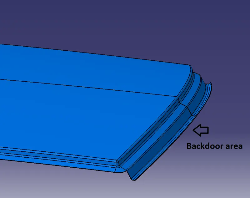
- Headroom Clearance, visibility criteria, clearance for Windshield and Back door are some of the factors to be considered while designing the Ditch Area.
- It is given a thickness of 0.75 mm.
- While designing the roof the edges are swept with the draft angle of 3 or more than 3 degrees since they are created using the pressing or drawing operation.
Front roof panel :
- The front roof is the part of the roof which connects the windshield and the inner panel of the hood and the bodyside outer.
- The front roof panel is created using the master section sketch given below.
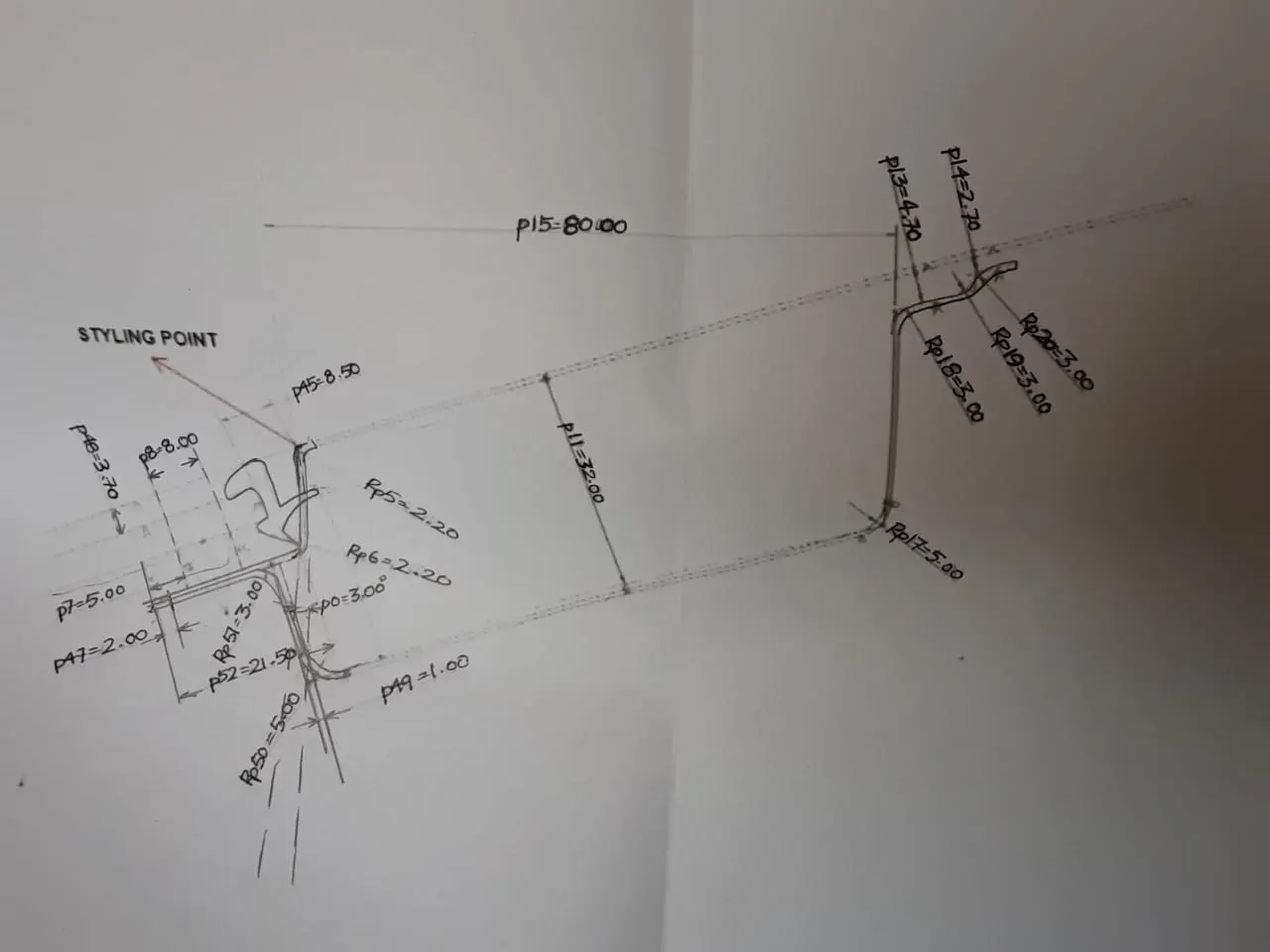
- Creation of the front roof is done by using the offset, sweep and trim tools.
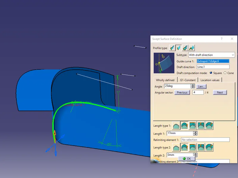
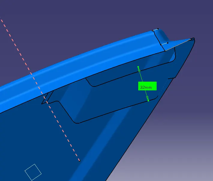
- The bottom-most surface or flange for the front roof is taken considering the headroom clearance for the passenger.
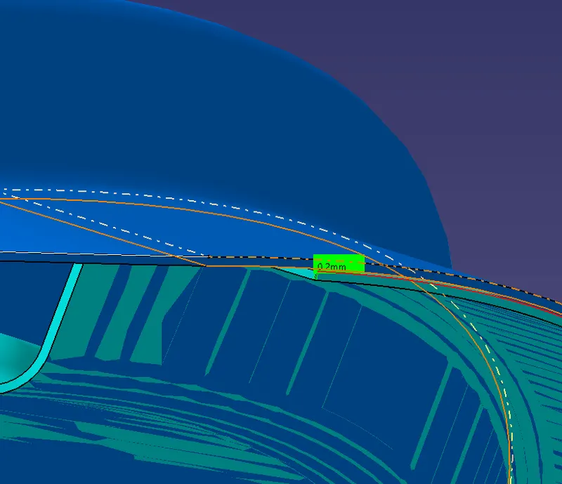
- The end flange which forms the connection for the windshield is taken at an offset to the roof surface with a minimum gap of 0.2 -0.1mm. This flange will be joined to the roof by spot weld as it won't be visible in the final assembly.
- For the other end of the panel, the offset distance is around 3-5 mm because it will be secured with a roof by mastic sealants which contribute to increased strength. The primary reason for using mastic sealants instead of spot welds is to maintain the appropriate visibility of the outer roof.
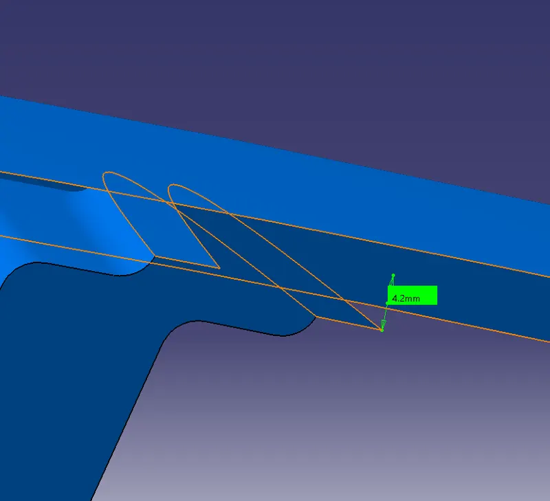
- In the end, the front roof panel is provided with a thickness of 0.75mm.
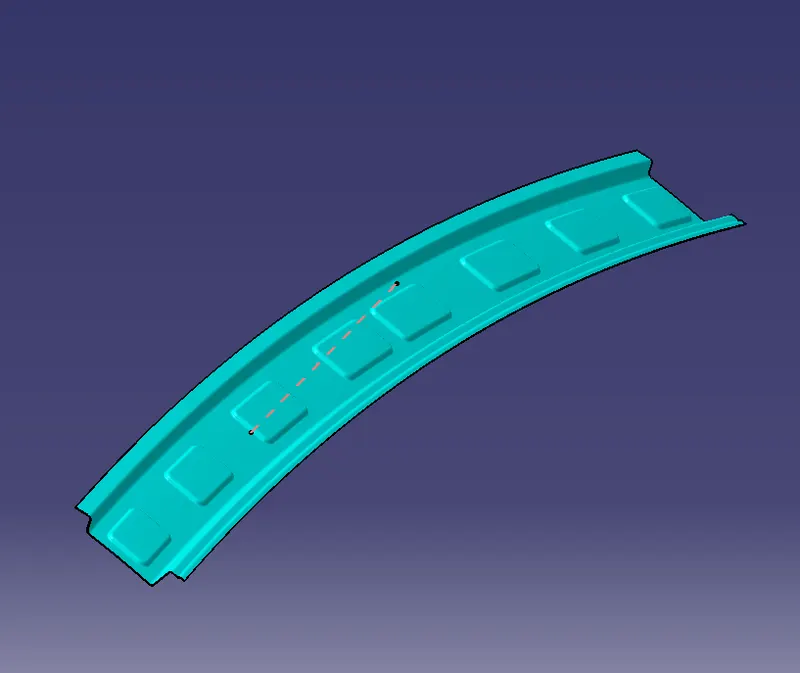
Rear roof panel :
- The rear roof rail is the support that joins the back door of the car and the bodyside outer.
- The back door design consideration has to be taken while designing the rear roof rail for proper clearance with the roof.
- The thickness for the rear roof rail is taken as 0.75mm.
- Same as the front roof rail, the rear roof bottom flange is taken considering the headroom clearance. Generally, the minimum headroom clearance for the rear roof rail is taken as 85mm but these standard changes from companies to companies.
- The bottom-most flange of the rear roof rail is around 50mm from the roof surface
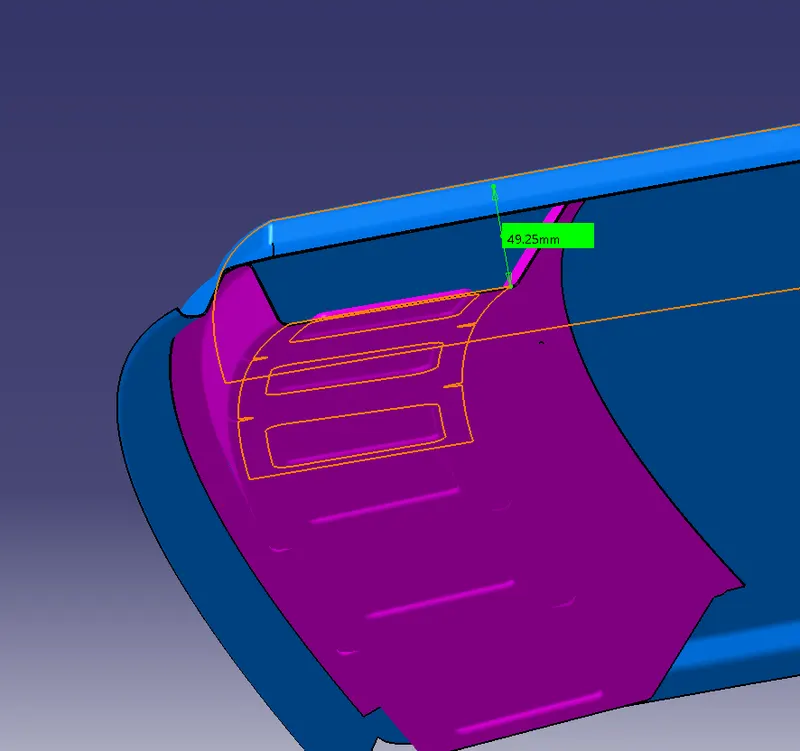
- Rest all the procedure to create the rear roof rail is the same as the front roof rail.
- Here also, the backdoor side is attached to a panel with the spot weld and the other end of the panel is connected to the roof by mastic sealants.
- Embosses are created to again improve the strength of the panel.
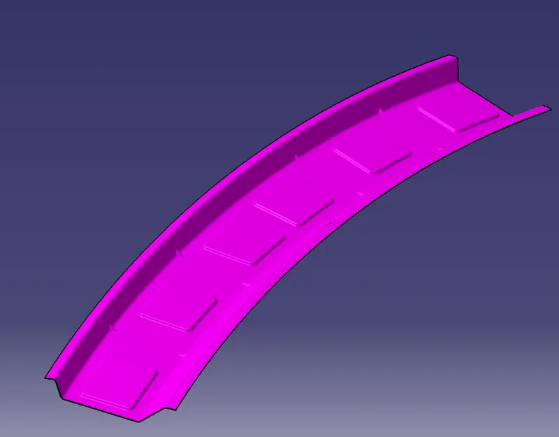
Center roof rail:
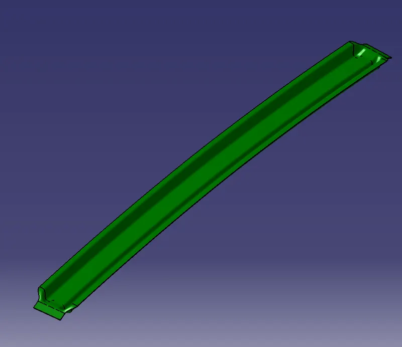
- Center roof rail is the reinforced support added to the roof to provide structural strength in the roll-over test and another test.
- For the center roof also headroom clearance is also taken into consideration. The bottom-most flange of the rail is around 32-35 mm from the roof surface.
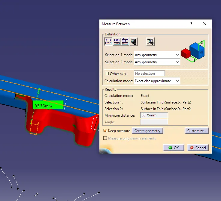
- Unlike the front and rear roof panel, the center roof rail is not joined with the roof spot weld but they are joined using the mastic sealants. The reason is that the rail is just below the roof i.e styling surface and joining them with spot weld will hamper the look of the roof as it will leave marks on it.
- Also using mastic points and sealants provide additional strength to the roof.
- Towards the end, the center roof rail will be joined with the ditch area of the roof using the nuts and bolts or spot welds.
- A surface is offset at the ditch area equal to the thickness of the roof and split to small and joined with the center rail using the multi sections.
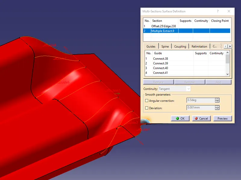
- The thickness of the center rail is around 1.2-1.5mm and it is placed at the center or coupled with the bow roof at a certain distance from the sunroof cutout edge for better strength to the component. Embosses are also created to improve the strength of the rails.
Bow roof rails :
- These are also the reinforcement members that help maintain the overall strength of the roof.
- The placement of the bow roof rail is not fixed, they are placed at different places that give the best results in the final design calculation.
- Generally, the bows are placed in the flatter region of the roof since they have less strength as compared to the curved regions.

- Same like center rail the bows are joined using the mastic sealants and in the ends with the nuts and bolts or spot welds.
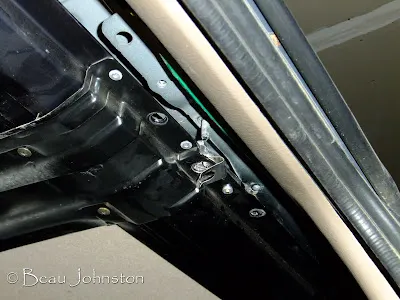
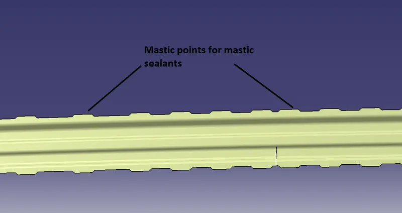
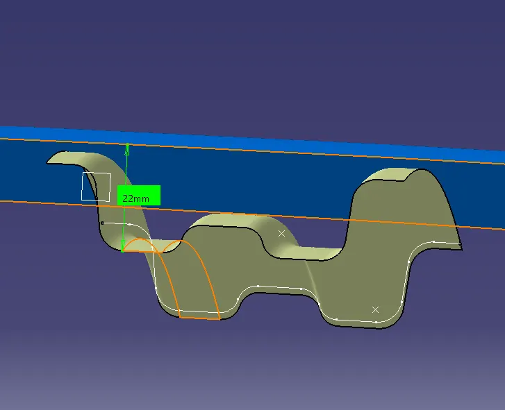
- The thickness for the bow rails kept here is 1-1.2mm and the gap with the roof surface is around 20-25mm. The only bow thickness coupled with the center rail is kept the thickness of 0.6mm.
- All the bow rails here are placed between the center roof rail and the rear roof panel.
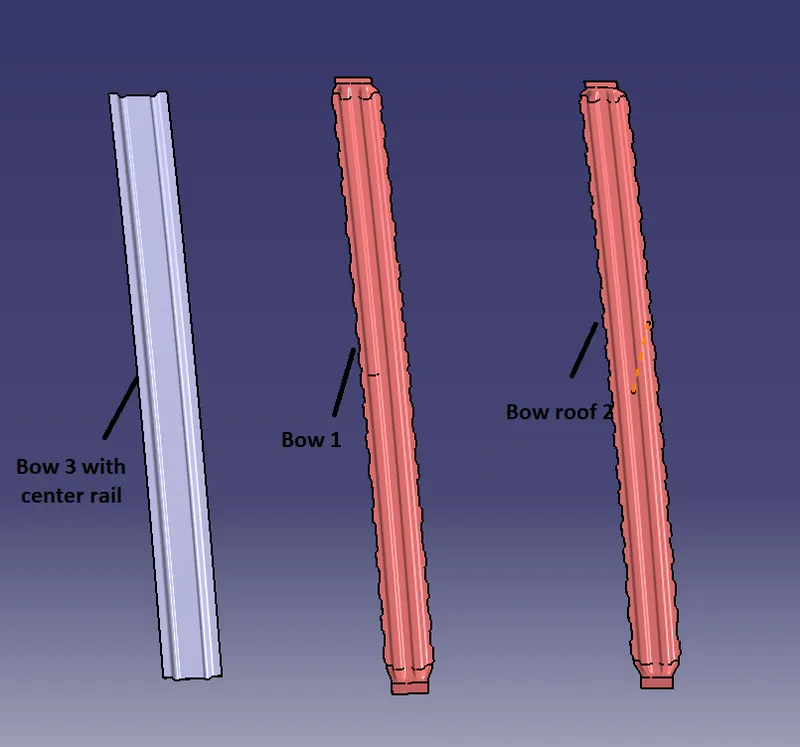
Note All the parts created with a proper draft angle of more than 3 degrees to make them manufacturable
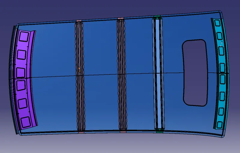
Curvature study for the roof :
The final designed roof assembly has to be checked and ensured if it meets the standard and able to deliver the required results.
So for that, there are some tests (static or dynamic) for the roof that justify the positioning of the bows and the final design. These tests are
- Heat distortion(static)
- Snow load(static)
- Roll over (dynamic )
Here we are only going to consider the static test for the roof.
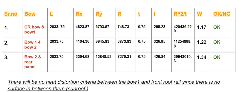
1.Heat Distortion Criteria:
Heat distortion test is a type of static load test which plays an important role in maintaining roof strength. Heat distortion temperature is the temperature at which metal softens and deforms under a specified load.
From Heat distortion criteria, roof strength can be enhanced by appropriate positioning of bow roof rails.
Bow – roof prediction Formula :
W=(1.73×10⁻³×L)+(1.85×10⁻⁸×R2t)+(1.10×10⁻³×l)−2.68W=(1.73×10⁻³×L)+(1.85×10⁻⁸×R2t)+(1.10×10⁻³×l)-2.68
where,
L = Roof Length in X-Direction[mm](Roof dimension in 0-Y)
R = Roof curvature = 2(Rx*Ry)/(Rx+Ry)
Rx = X curvature
Ry = Y curvature
t = Roof plate thickness [mm]
l = Bow Roof Span [mm]
Judgement Condition: OK < 2.7mm ≤ NG
2.Snowed Criteria:
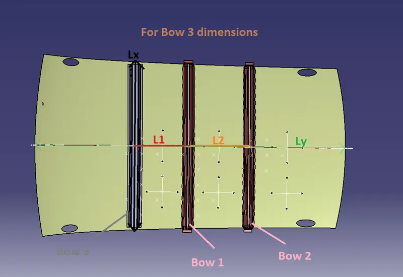
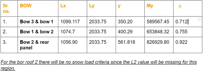
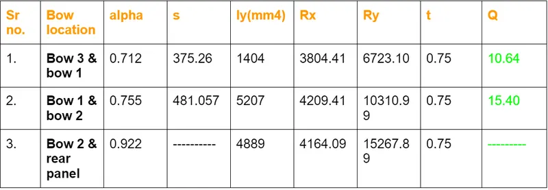
The snow load test is a type of static load test used to verify that roof assembly exhibits no permanent deflection due to a distributed load representing snow load: the distributed pressure applied is in the range 10-15 N/dmᶺ2.
Qr=Iy×t2α×s×(Rx+Ry2)2×10⁻⁸Qr=Iy×t2α×s×(Rx+Ry2)2×10⁻⁸
α=My×L2x×10−12α=My×Lx2×10−12
My=Y(Ly−Y)My=Y(Ly−Y)
where,
Ly = Distance between front and rear roof rails[mm]
Lx = Distance between left and right end roof rails[mm]
Y = Distance between centre of front roof rail to centre of bow roof rail [mm]
S = Distance for which roof bow bears divided load [mm]
Iy = Geometrical moment of inertia of roof Bow (Y cross-section) [mm4]
Rx = Lateral direction curvature radius of roof panel Y cross-section on roof bow
Ry = Longitudinal direction curvature radius of roof panel X cross-section on roof bow
t = Roof plate thickness [mm]
Section modulus :
Section modulus is a geometric property for a given cross-section used in the design of beams or flexural members. There are two types of section moduli, the Elastic Section Modulus and the Plastic Section Modulus. For general design, the Elastic Section Modulus is used, applying up to the Yield Point for most metals and other common materials. Section modulus is calculated using the formula
S=IyS=Iy
Where,
S = Section Modulus
I = Moment of Inertia
Y = distance between the neutral axis and the extreme end of the object
The section modulus is the ratio of bending moment to bending stress for steel.
According to bending moment equation:
S=IyS=IyMI=ER=σyMI=ER=σy
Now,
MI=σyMI=σy
Therfore,
Mσ=IyMσ=Iy
MI=S(Iy=sectionmodu––s)MI=S(Iy=sectionmodu̲s)
For Ex:- If your steel has a high section modulus it will be harder to bend and can withstand a high moment without having high bending stress.
We need to divide the maximum bending moment by the section modulus to get the bending stress and then compare the bending stress to the allowable tensile stress to see if the steel can take that much moment.
Section modulus is inversely proportional to the bending stress. That means sections having a high section modulus will have lower bending stresses.
Procedure for finding the section modulus :
Section modulus for center rail and bow roof 3
- Use the intersect to intersect the center and bow rail with the XY plane. The output will be the boundary lines for both rails.
- Now use the multi-extract to extract the outer boundary of the center rail and the inner boundary of the bow roof rail.
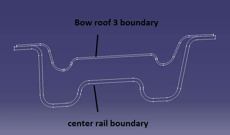
- Draw a line and join them to form closed lines.
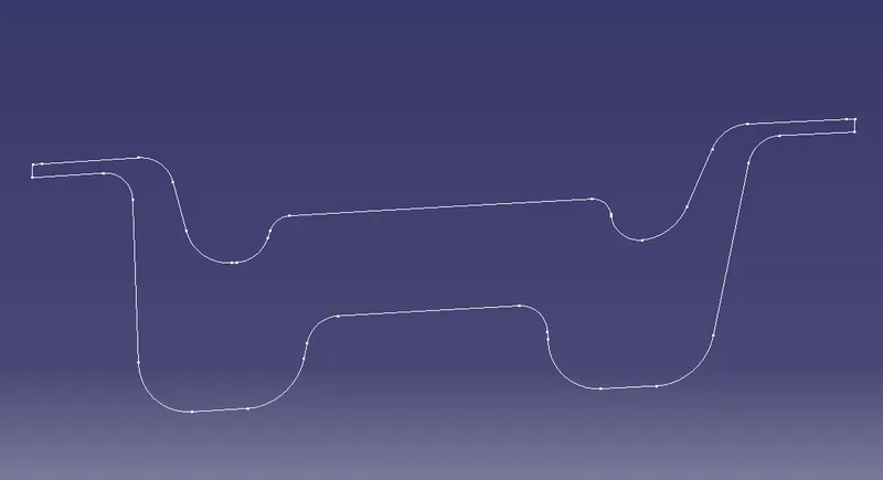
- Use the fill option to create the surface for the closed lines.
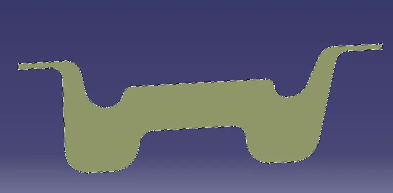
- Now, use the measure inertia for 2d to measure the inertia of the surface. The minimum value of M will be the moment of inertia for the given surface.
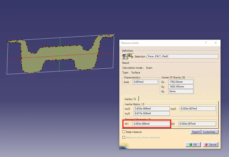
- For y i.e distance between the neutral axis and extreme end, go the sketch draw a line connecting the mid of the opposite edges. And then draw a straight vertical line from these two points to measure the distance as 2*y.
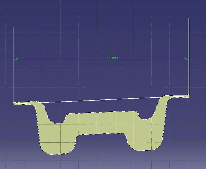
I=5.655×10⁻⁸m4I=5.655×10⁻⁸m4
I=5655mm4I=5655mm4
y= 95.90/2
y= 47.95 mm
S=1179.35mm3S=1179.35mm3
Bow 1:
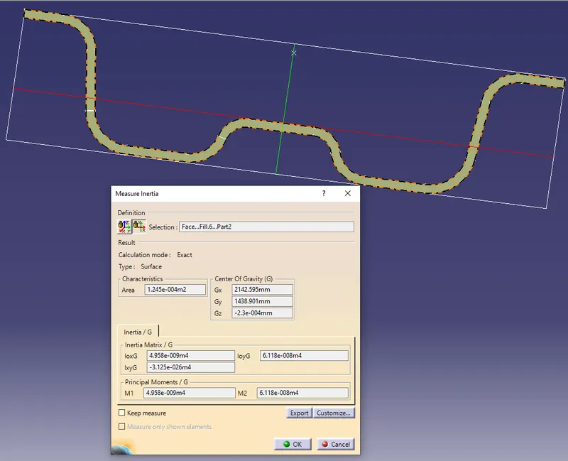
y=36.95 mm
I=4958mm4I=4958mm4
S=134.18mm3S=134.18mm3
Bow 2:
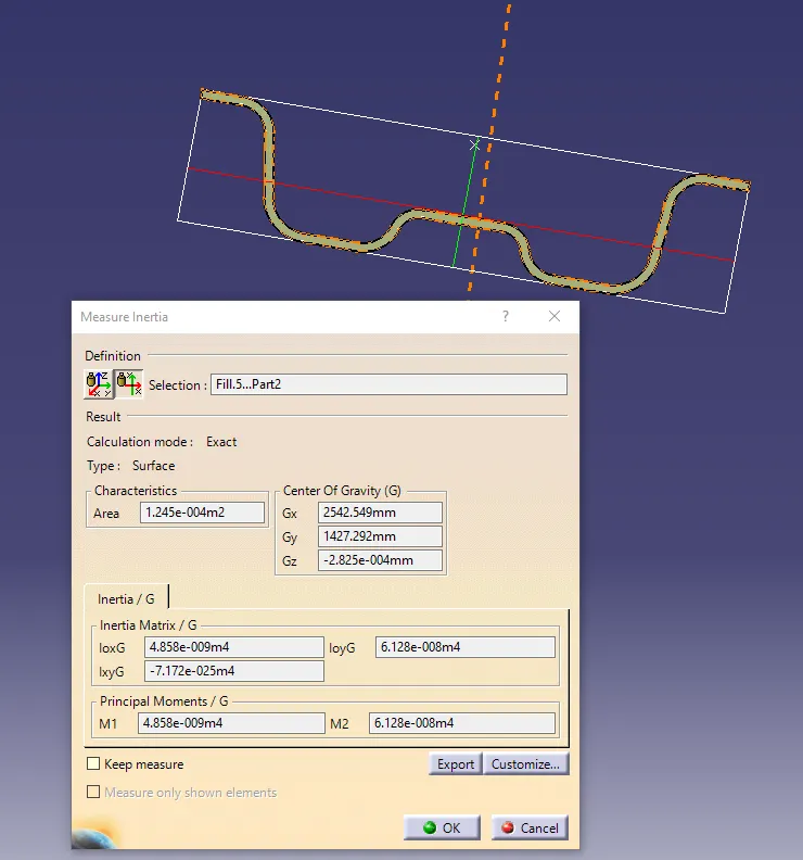
y=36.95 mm
I=4858mm4I=4858mm4
S=131.30mm3S=131.30mm3
Front roof panel :
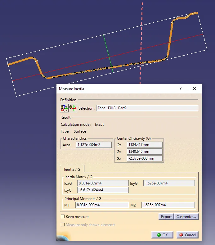
y= 56.61 mm
I=8081mm4I=8081mm4
S=142.74mm3S=142.74mm3
Rear roof panel :
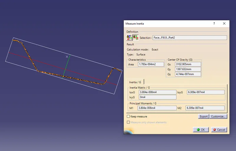
y=96.21 mm
I=3804mm4I=3804mm4
S=395.83mm3S=395.83mm3
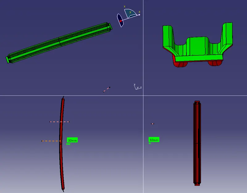
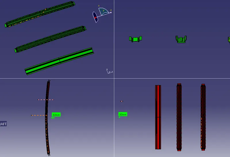
Draft analysis :
Every part that is designed from the point of view should be manufacturable with no distortion or failure in extraction.
Like the plastic component manufactured by injection molding, an appropriate draft is given to the body so that parts can be injected properly.
Here also the sheet metal components are prepared by drawing or pressing operation, so they need to be provided for the draft and checked for the draft analysis.
ROOF :
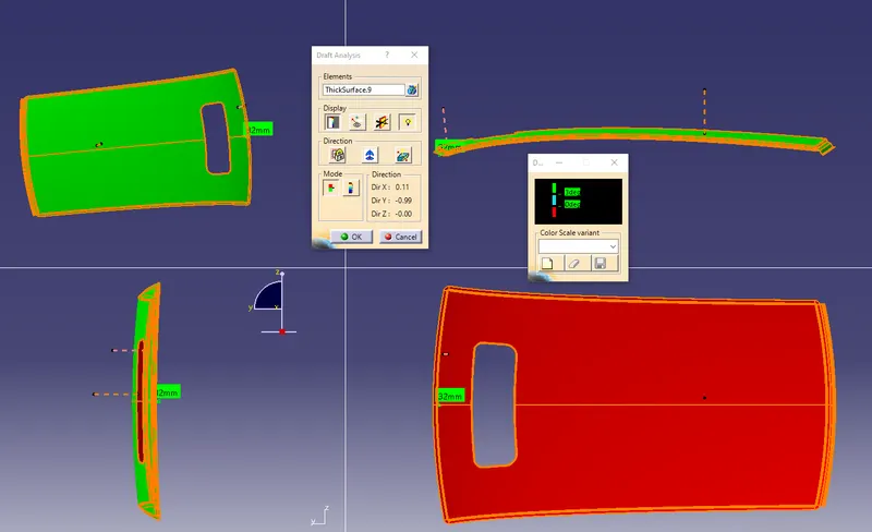
FRONT ROOF PANEL:
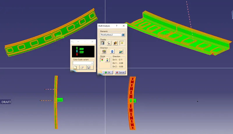
REAR ROOF PANEL :
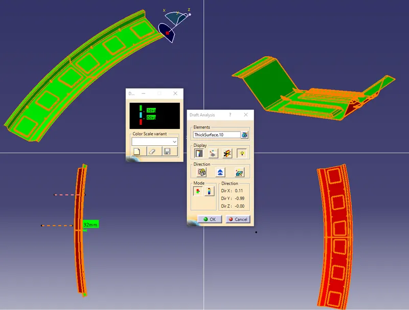
CENTER RAIL:
BOW ROOF :
CONCLUSION :
- The final roof with ditch area, structural rails were designed properly using the master sketch and certain clearance standards for the inside cabin space.
- The validation of the design was satisfactory but can be improved especially the heat distortion by changing the positions of the bow roof surface.
- Also, the embosses can be created on the roof and certain areas to improve the strength but creating embosses slightly increases the cost of manufacturing. So it depends on the overall cost and company decisions.