Roof challenge
Introduction:
In this project, we will study the roofs, bow roofs and reinforcement for the roof, different design considerations, how to develop the design to the component with the master sections and the skin data provided.
Roof assembly:
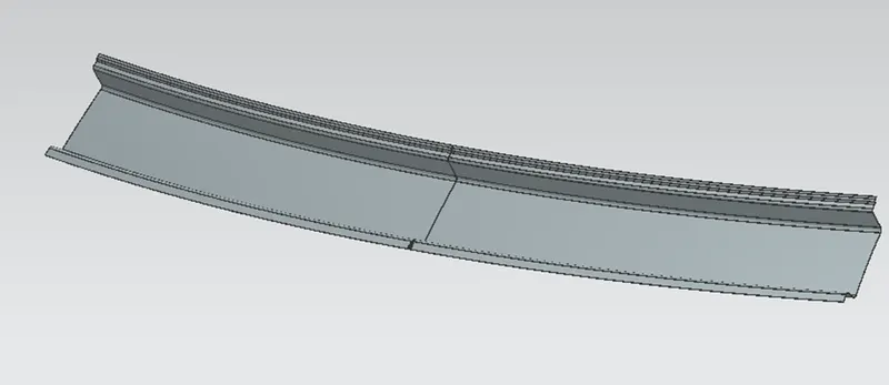
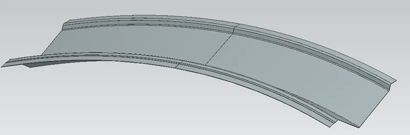
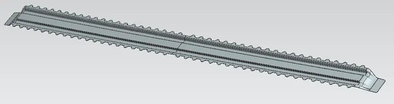
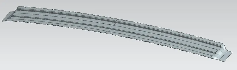
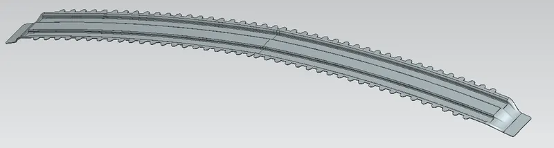
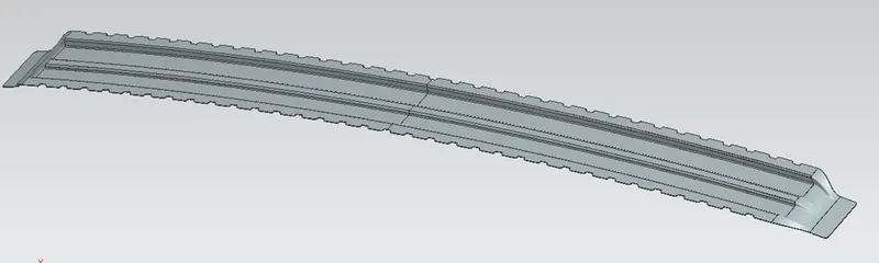
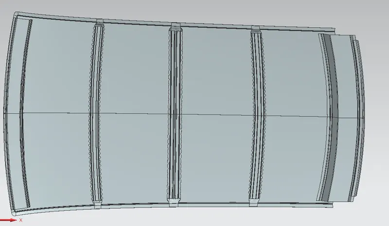
The roof assembly has the following parts
- Roof ditch panel
- Bow roofs (3 numbers)
- Reinforcement roof rail
- Front rail
- Rear rail
Roof ditch panel:
This is the aesthetic part of the vehicle which is visible to human eye. This is the top most part of the vehicle. The design of roof is done using the master sketch given giving appropriate draft angle for sheet metal production.
Front Rail:
This is the part that connects the roof ditch panel to the A-pillar of the car. Except for the roof panel all other parts provides strengthening aids to the roof panel. The Front rail is welded to the A pillar and the roof panel. The front rail comes in the front part of the vehicle.
Rear Rail:
This part connects the roof panel to the rear pillar. This part is designed as per the opening of the rear door of the Vehicle. The design is done as per the master sections provided.
Bow Roofs:
These parts are added to increase the load-carrying capacity of the roof of the car. Three bow roofs are designed for our project.
Center reinforcement:
The centre reinforcement is given to add more stiffness to the roof. It helps in increasing the load-carrying capacity of the roof and resists to deformation caused due to any snow settling over the roof.
Analysis:
Draft analysis:
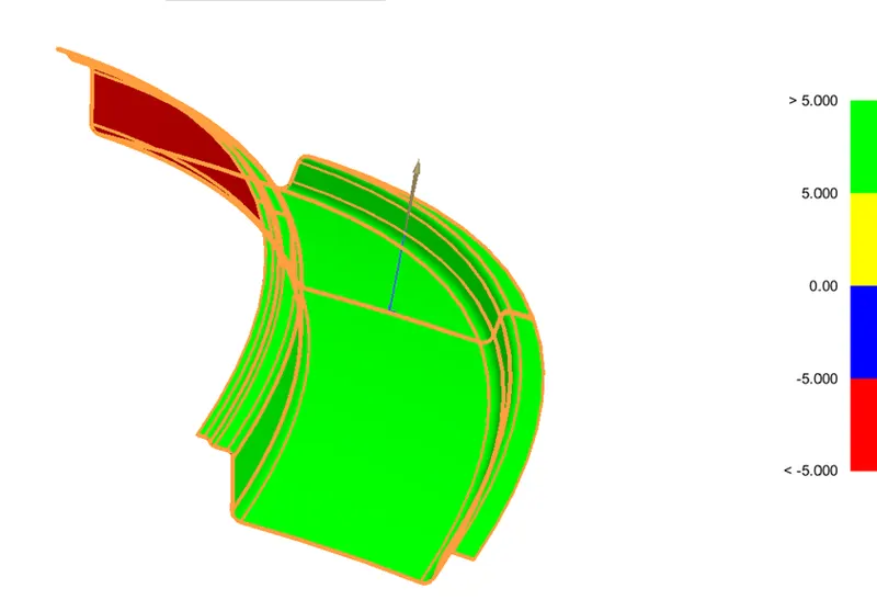
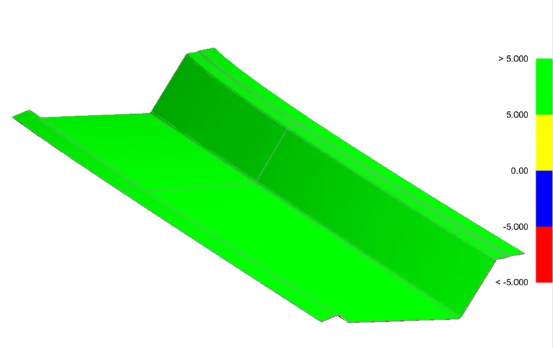
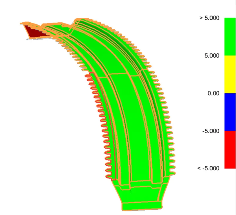
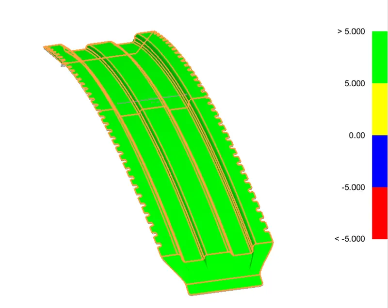
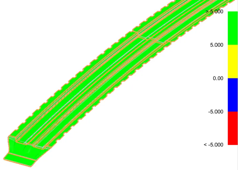
All our products are prepared in sheet metal raw material. So appropriate draft should be given to the parts we design, only then the part can be manufactured. The draft of the parts should be handled in the design stage itself. A draft angle of a minimum of 7 degrees is given to the parts.
1. Front roof rail: A separate tooling axis is provided for the draft of the front roof rail.
2. Back roof rail: The y-axis is considered for the draft of the sheet metal as the tooling axis.
3. Bow roof 1: The y-axis is considered for the draft of the sheet metal as the tooling axis.
4. Bow roof 2: The y-axis is considered for the draft of the sheet metal as the tooling axis.
5. Bow roof 3: The y-axis is considered for the draft of the sheet metal as the tooling axis.
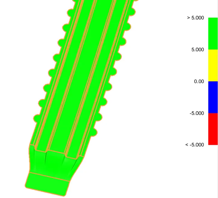
6. Centre reinforcement: The y-axis is considered for the draft of the sheet metal as the tooling axis.
Section modulus analysis:
Front roof Rail:
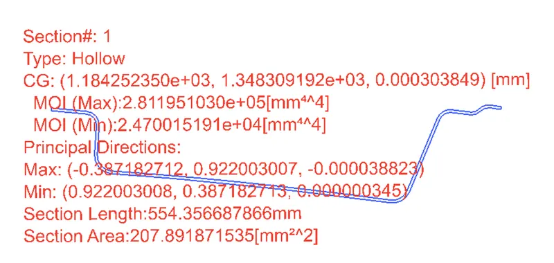
Back roof Rail:
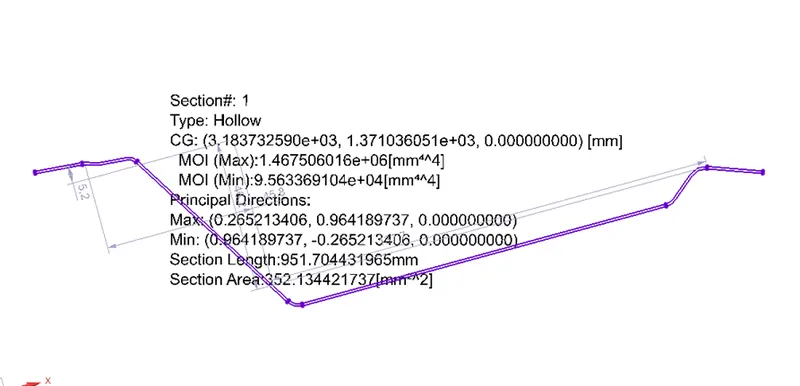
Bow roof 1:
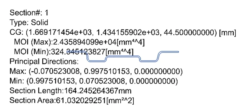
Bow Roof 2:
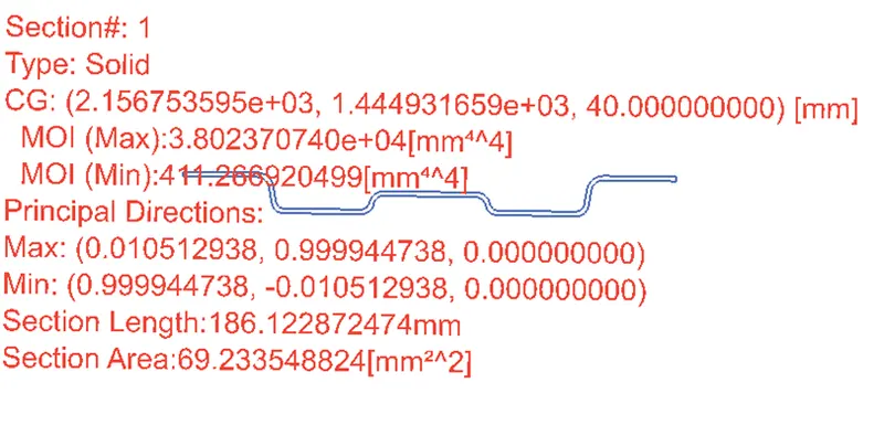
Bow roof 3:
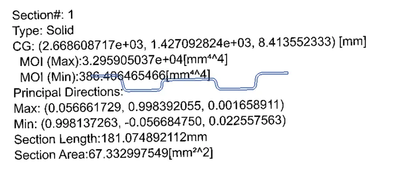
Centre reinforcement:
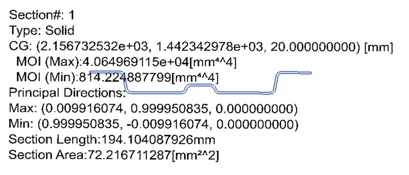
Heat distortion and snow load analysis:
Heat distortion analysis:
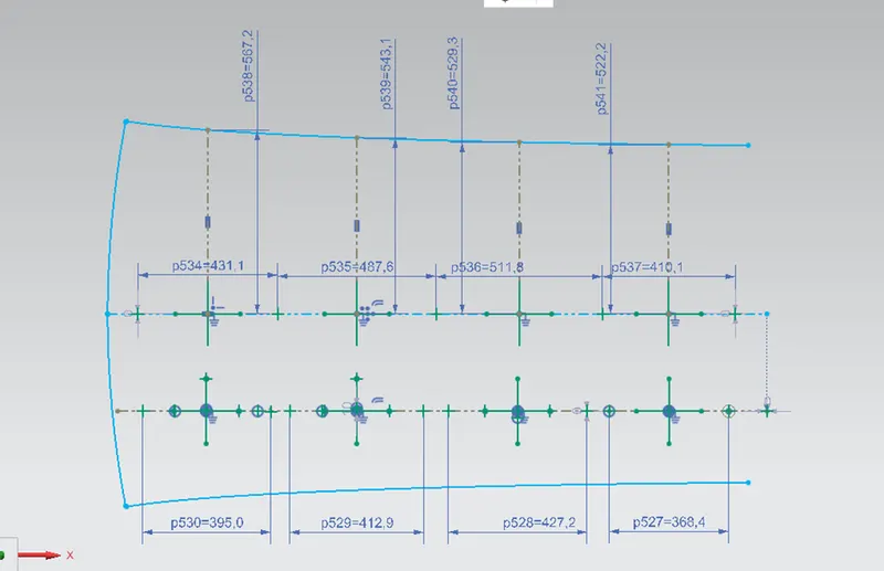
The location of the bow roof and reinforcements are determined prior to the start of design. This helps in reducing the work of analysis engineer for crash and snow load tests. All the values are created based on the formula given below.
Formula:
W = [1.73 x 10^(-3) x L] + [1.85 x 10^(-8) x (R^2)/t] + [ 1.10x10^(-3) x l] - 2.68
Judgement Condition : W< 2.7
Where
L = Roof Length in X-Direction[mm](Roof dimension in 0-Y)
R = Roof curvature
R = 2(Rx*Ry)/(Rx+Ry)
Rx = X curvature
Ry = Y curvature
t = Roof plate thickness [mm]
l = Bow Roof Span [mm]

Snow load:
Formula:
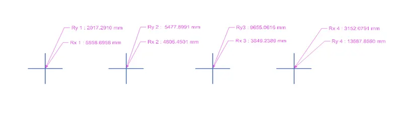
Qr = [Iy x t2] / [α x s x [(Rx + Ry)/2]2 x 10-8]
Where
α = My x Lx2 x 10-12 , My = Y(Ly-Y)
Judgement condition = Qr ≥ 3.1
t = Roof plate thickness [mm]
Ly = Distance between the front and rear roof Rails on the Vehicle along with 0Y[mm]
Length of Roof panel with the centre point between Roof rail Front /Rear as the front and rear reference point.
Lx = Distance between the Left and Right end of the roof on the Roof BOW [mm]
( Width of the roof panel exposed on the surface.)
Y = Distance front Front Roof Rail to Roof BOW[mm]
s = Distance for which Roof BOW bears divided load [mm]
s = L1/2 + L2/2
Iy = Geometrical moment of inertia of Roof BOW (Y cross-section )[mm4]
Rx = Lateral direction curvature radius of roof panel Y cross-section on Roof BOW [mm]
Roof panel curvature Radius of the Length Lx in Front view
Ry = Longitudinal Direction curvature radius of the Roof panel X cross-section on Roof BOW [mm]
Roof panel X curvature radius of length s in Side view
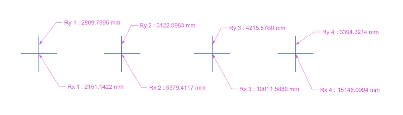

- All the values are taken from the model and tabulated above.
- The W value for different sections are calculated and shown above.
- All the values of W clears the judgement criteria.
- Similarly for snow load condition all the values are tabulated and the values are entered as per the model
- The Qr values are calculated and checked for the judgement criteria.
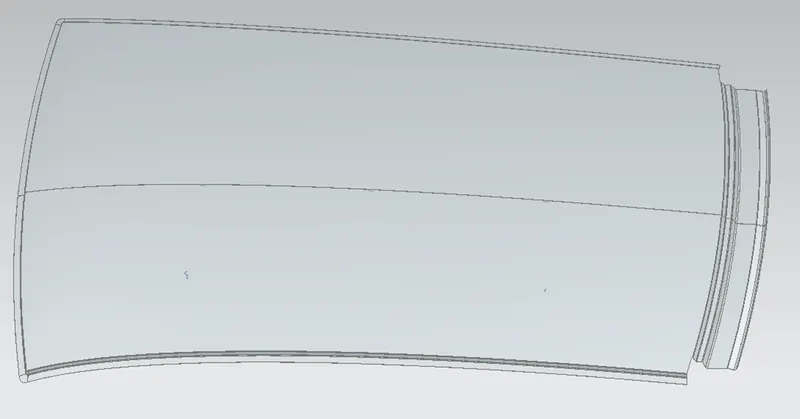
Images of assembly:
Conclusion:
All the models are created using the CAD tool and the bow roofs are created with respect to the heat distortion criteria. The Section modulus and draft analysis is done for all the parts. The snow load criteria is calculated for the parts.