Roof challenge
AIM
- The aim of the project is to design car roof with essential flanges and reinforcements like ditch area, front roof rail, bow roofs, center roof with reinforcement and rear roof rail for the given styling roof.
- To perform a curvature study on the roof and perform the calculations for the heat distortion and snow load criteria to satisfy the design considerations.
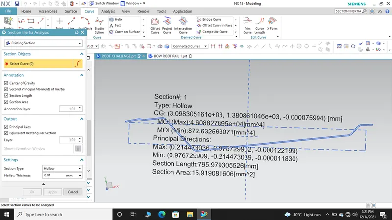
- To find the moment of inertia and section modulus for front roof, bow roofs, center roof rail and rear roof rail.
MASTER SECTIONS
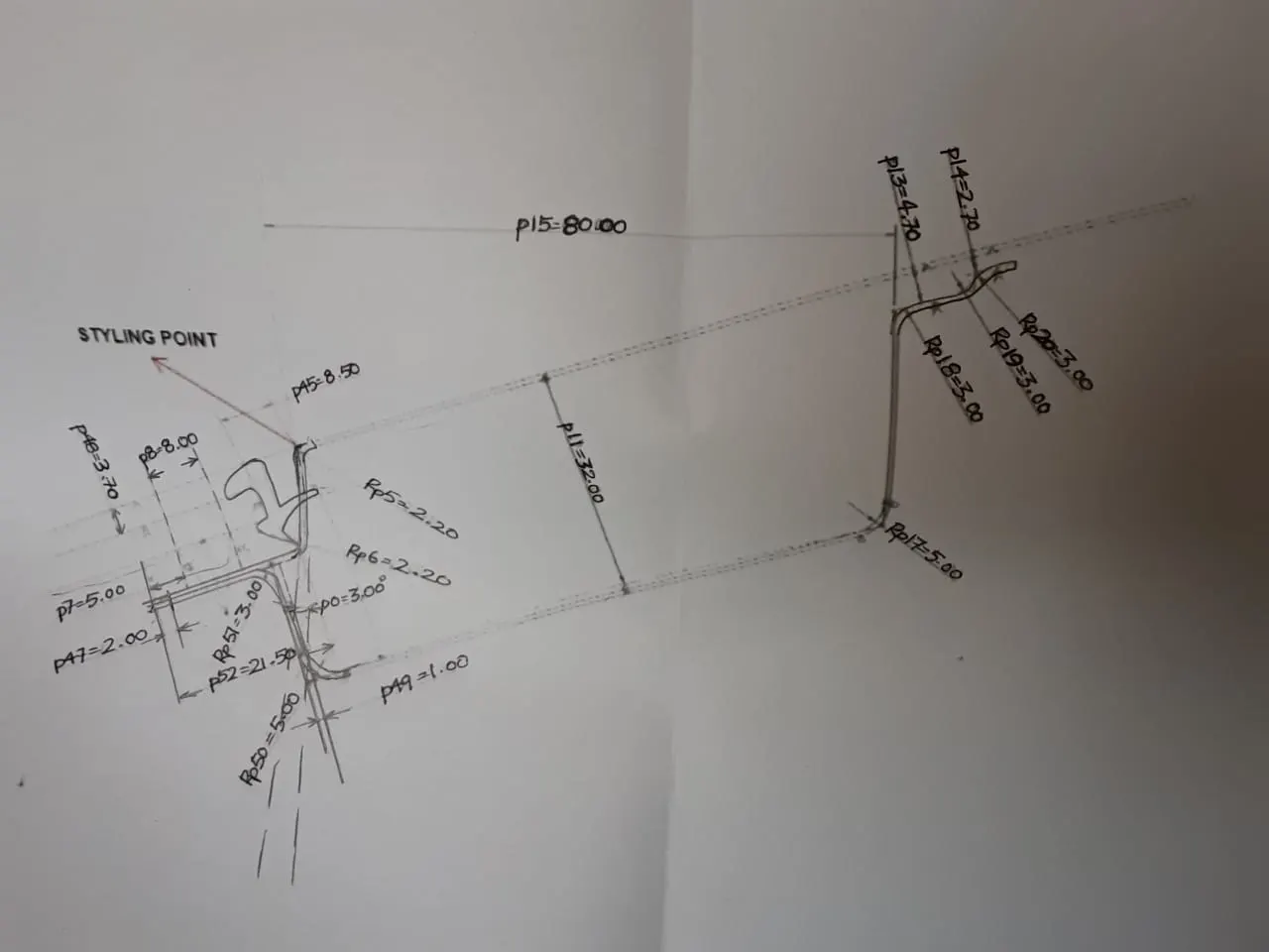
Front roof Rail master section reference image
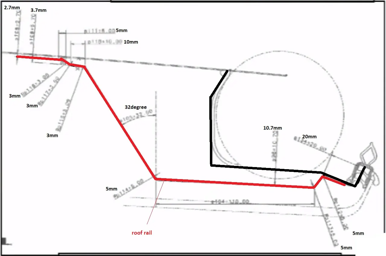
Rear roof rail master section reference image
INTRODUCTION
CAR ROOF
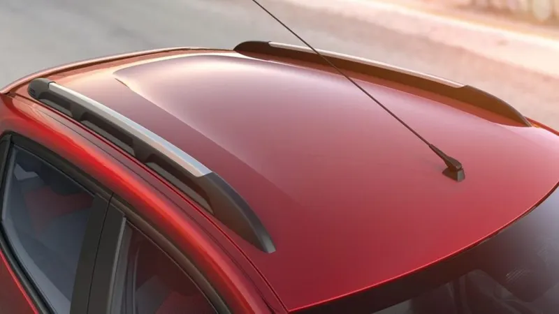
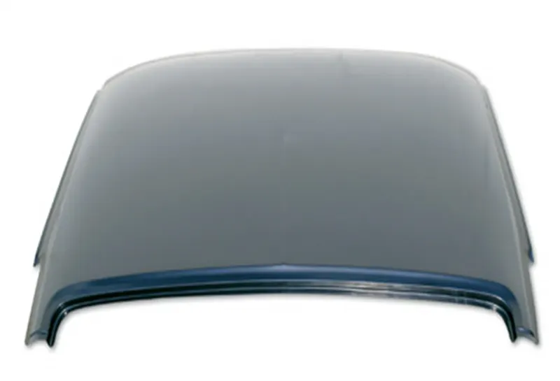
- An automobile roof or car top is the portion of an automobile that sits above the passenger compartment, protecting the vehicle occupants from sun, wind, rain, and other external elements.
- Because the earliest automobiles were designed in an era of horse-drawn carriages, early automobile roofs used similar materials and designs.
ROOF ASSEMBLY
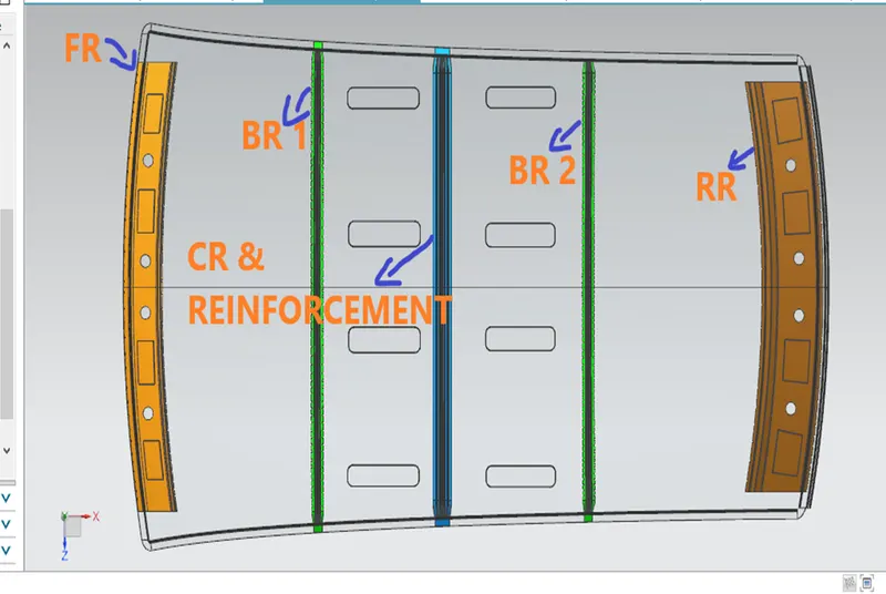
COMPONENTS OF THE ROOF
- Front roof rail
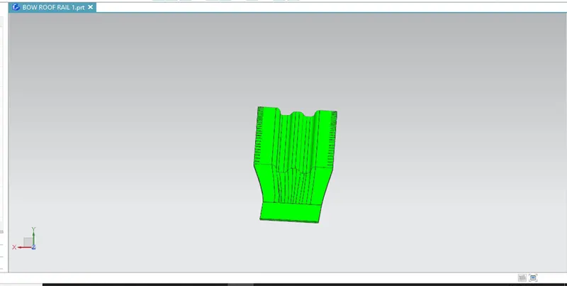
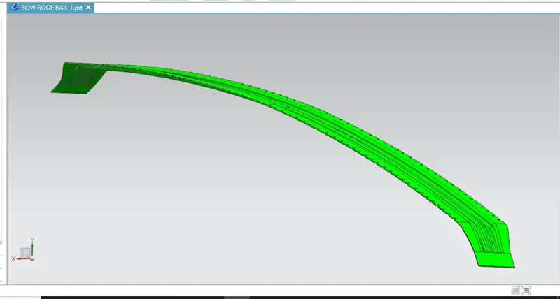
- Bow roof rail 1
- Center roof rail with Reinforcement
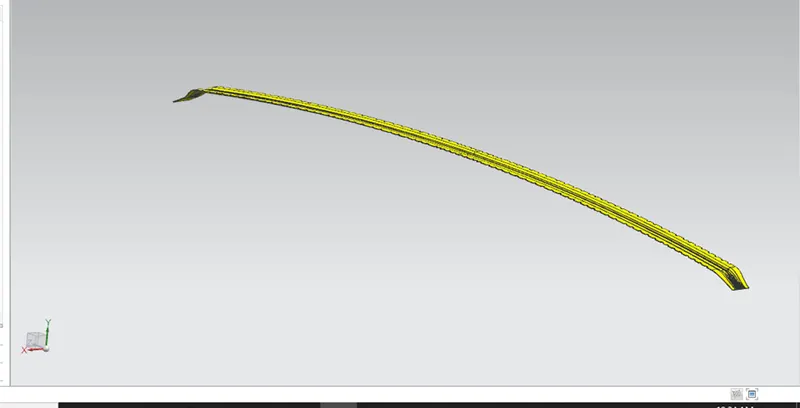
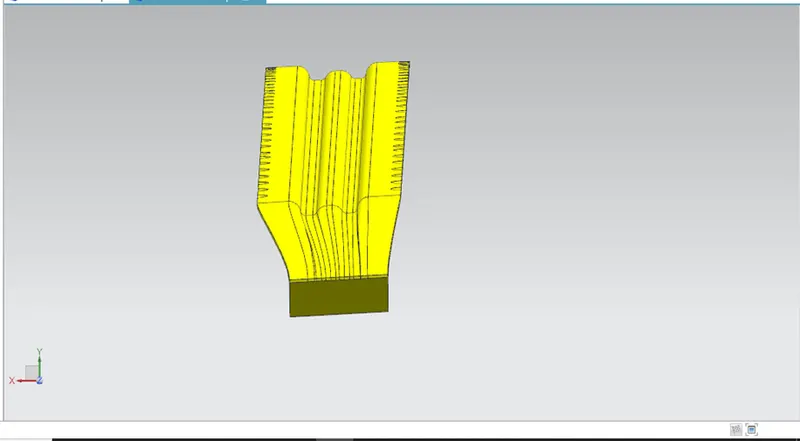
- Bow roof rail 2
- Rear roof rail
PROCEDURE
DITCH AREA AND FRONT ROOF RAIL
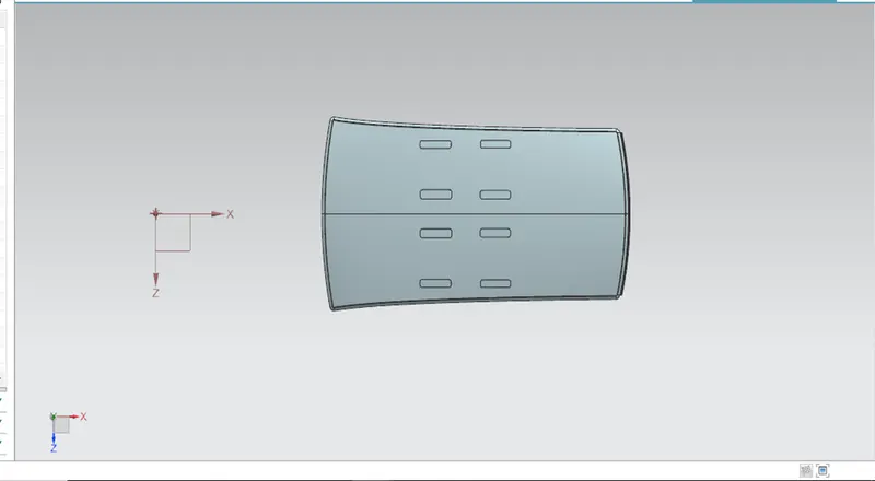
- After receiving the skin data from the styling team, Roof outer panel should be extracted and untrimmed.
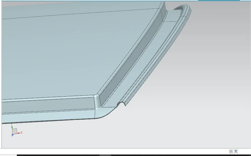
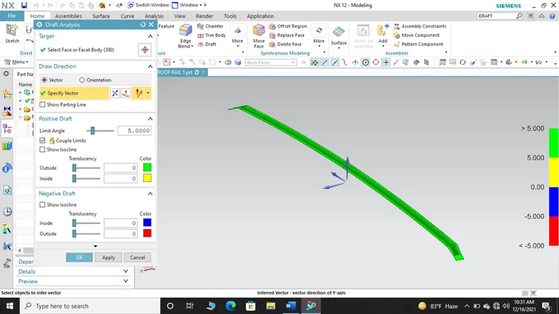
- From the edge of the roof outer panel, law extension is done with an angle of 3 degrees.
- The draft angle should be in the range of 3-4 degrees as deep- drawing operation is involved.
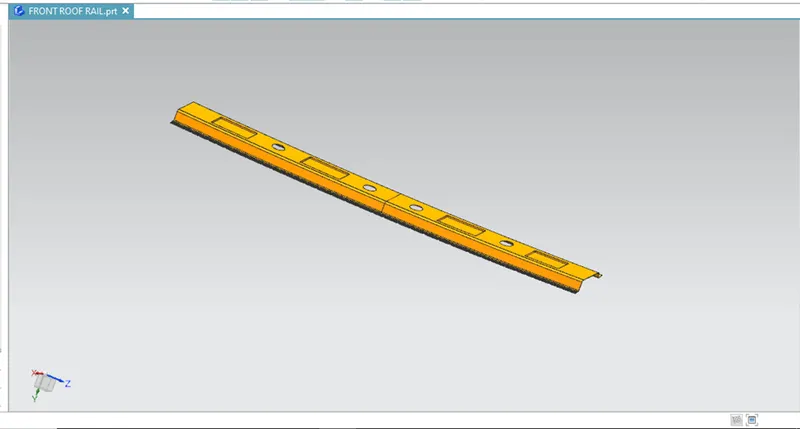
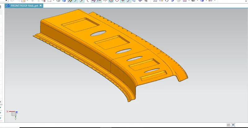
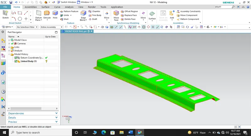
- Front roof rail is the support that joins the windshield glass, bodyside outer and the inner panels.
- The thickness of the Front roof rail is given as 0.75mm and the thickness of the roof outer panel with ditch area is also 0.75mm thick.
BOW ROOF RAIL
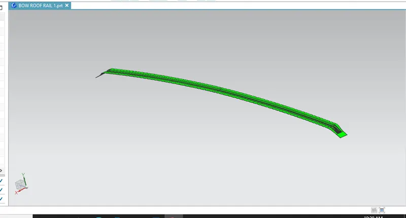
- Bow roof rails are the intermediate components of the roof which strengthens the roof and to provide support along with the three primary roof rails such as Front roof rai., Center roof rail, Rear roof rail.
- Bow roof rail can be in many numbers depending upon the type and class of the vehicle and it all depends on the design intent.
- These bow roofs are joined to the roof by using the mastic sealants.
- In this challenge, I have designed 2 bow roof rail such as Bow roof rail 1 (BRR 1) and Bow roof rail 2 (BRR 2) as per the design requirement, class and type of the vehicle.
BOW ROOF RAIL 1
BOW ROOF RAIL 2
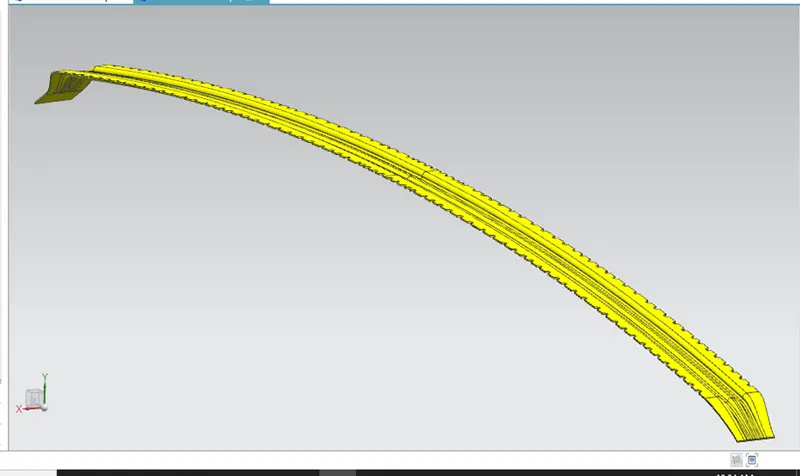
CENTER ROOF RAIL WITH REINFORCEMENT
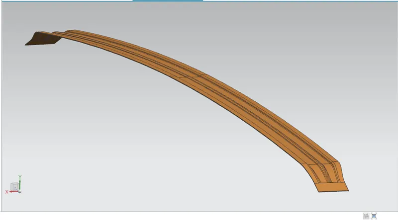
- Center roof rail is placed exactly at the center of the roof.
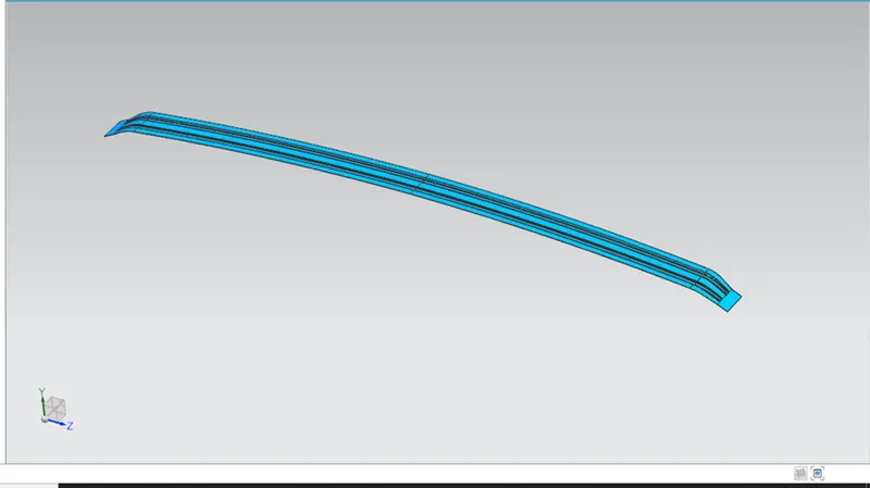
- Another rail is added to the center roof rail to give more strength to the roof.
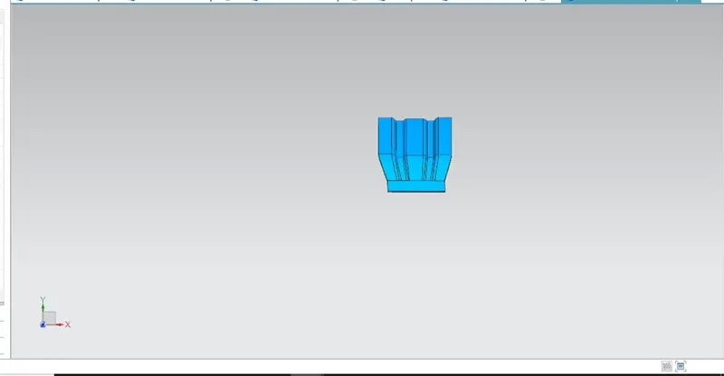
- It is designed with the help of the master section provided.
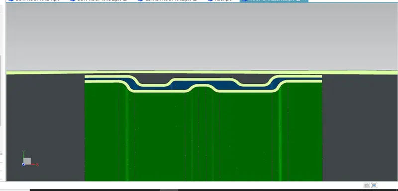
CENTER ROOF
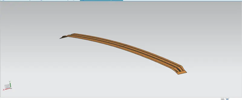
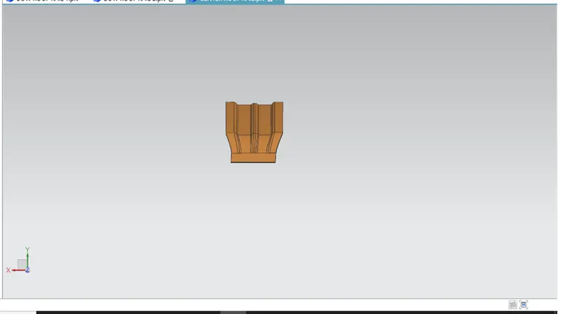
REINFORCEMENT
REAR ROOF RAIL
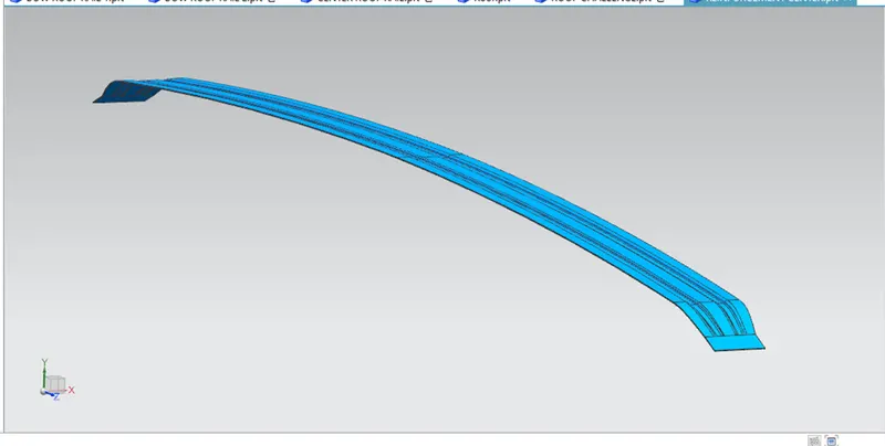
- Rear roof rail is joined to the backdoor, the bodyside outer and the inner panels.
- Backdoor design should also be considered for designing the rear roof rail as it helps to design the rear roof with headroom clearance and the rear visibility criteria.
- Spot welds are applied at the backdoor end of the rail and the Mastic sealants are used to join the other end of the rail.
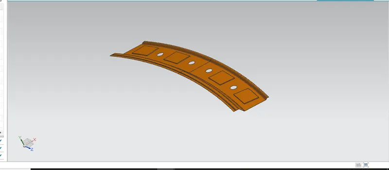
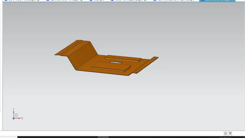
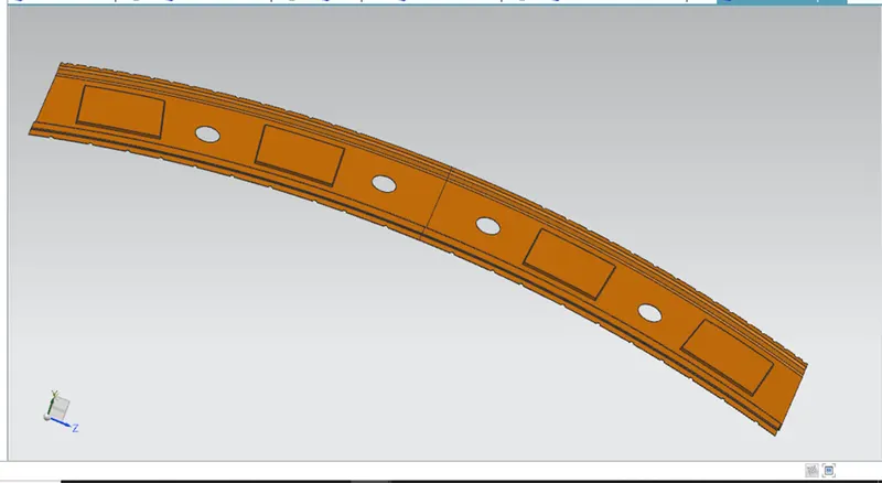
ROOF OUTER PANEL
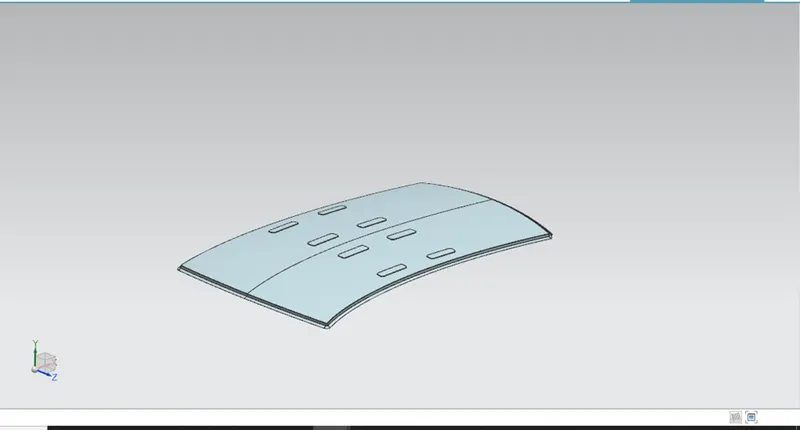
DITCH AREA
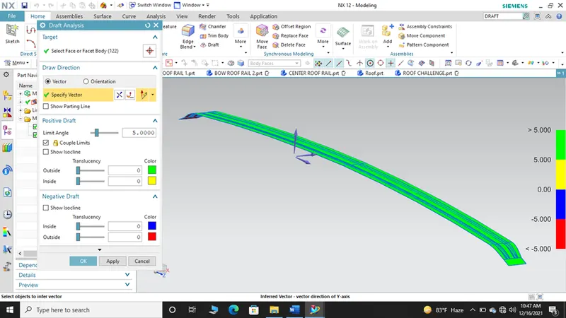
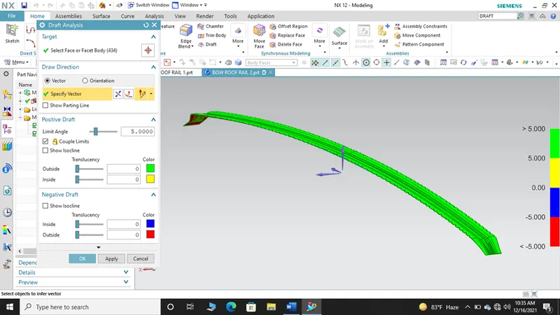
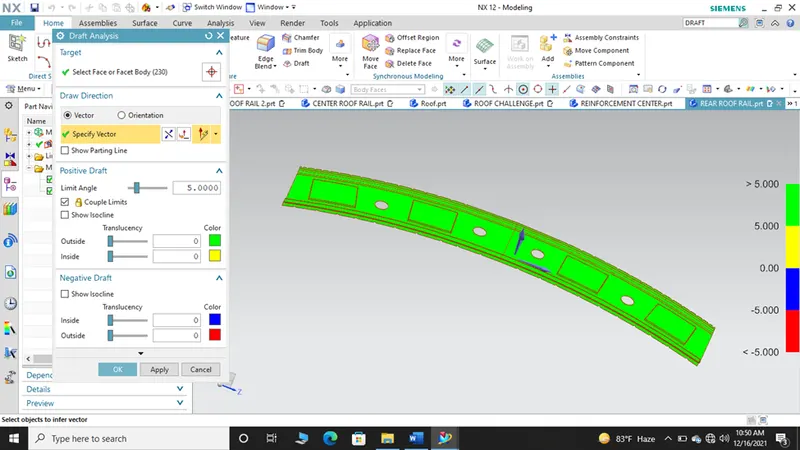
DRAFT ANALYSIS
FRONT ROOF RAIL
BOW ROOF RAIL 1
CENTER ROOF AND REINFORCEMENT
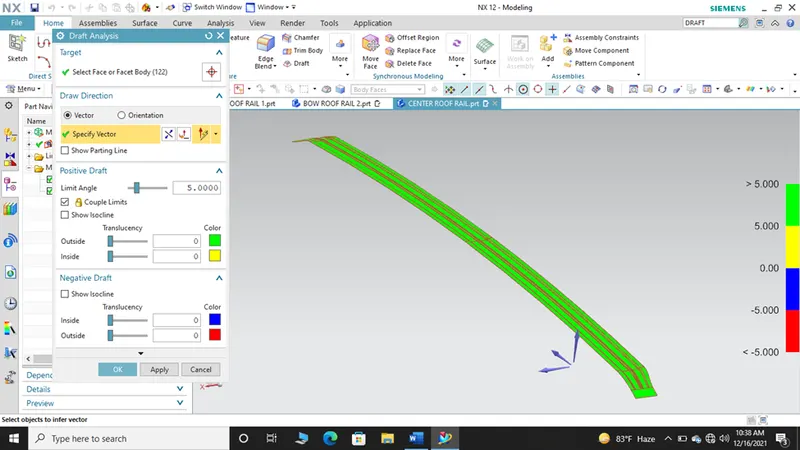
REINFORCEMENT
BOW ROOF RAIL 2
REAR ROOF RAIL
HEAT DISTORTION CRITERIA
- Heat distortion temperature is the temperature at which the metal softens and deforms under a specific load.
- The heat radiating from the sun causes the roof of the car to change in the metallic regions
- This study is done to check the ability of the roof to withstand high temperature with respect to the positioning of the reinforcements which contribute to increased strength.
W= [1.73 * 10^(-3) * l] + [1.85 * 10^(-8) * (R^2)/t] + [1.10 * 10^(-3) * l] – 2.68
Judgement Condition = OK <2.7> 3.1
Where,
L = Roof Length in X- Direction (mm) (Roof dimension in O-Y)
R = Roof Curvature
R= 2(Rx* Ry)/(Rx+Ry)
Rx = Curvature of X
Ry = Curvature of Y
t= Roof plate thickness (mm)
l= Bow Roof Span (mm)
|
ROOF BOW |
Rx |
Ry |
R |
l |
L |
t |
R^2/t |
W |
OK/NG |
|
FR&BR |
5670.17 |
2754.94 |
3708.20 |
433.82 |
2039.54 |
0.75 |
18334329.6 |
1.66 |
OK |
|
BR 1 & CR |
4880.86 |
6843.6379 |
5398.22 |
324.36 |
2039.54 |
0.75 |
38854372.23 |
1.92 |
OK |
|
CR & BR2 |
4061.6944 |
10332.82 |
5831.21 |
387.11 |
2039.54 |
0.75 |
45337346.75 |
2.09 |
OK |
|
BR 2 & RR |
3506.16 |
14491.58 |
5646.25 |
496.42 |
2039.54 |
0.75 |
42506957.48 |
2.15 |
OK |
SNOW LOAD CRITERIA
- Snow load criteria study is done to check the ability of the roof to withstand snowfall and bounce back to its original shape without any permanent deformation once the load is removed.
Snow load prediction formula,
Qr = [Iy x t2] / [α x s x [(Rx + Ry)/2]2 x 10-8]
Where,
α = My x Lx2 x 10-12 , My = Y(Ly-Y)
Judgement condition = Qr ≥ 3.1
250 ≤ s ≤ 380
t = Roof plate thickness [mm]
Ly = Distance between the front and rear roof Rails on the Vehicle along with 0Y[mm]
Length of Roof panel with the center point between Roof rail Front /Rear as the front and rear reference point.
Lx = Distance between the Left and Right end of the roof on the Roof BOW [mm]
Width of the roof panel exposed on the surface.
Y = Distance front Front Roof Rail to Roof BOW[mm]
s = Distance for which Roof BOW bears divided load [mm]
s = L1/2 + L2/2
Iy = Geometrical moment of inertia of Roof BOW (Y cross-section )[mm4]
Rx = Lateral direction curvature radius of roof panel Y cross-section on Roof BOW [mm]
Roof panel curvature Radius of the Length Lx in Front view
Ry = Longitudinal Direction curvature radius of the Roof panel X cross-section on Roof BOW [mm] Roof panel X curvature radius of length s in Side view
SNOWED CONDITION
|
ROOF BOW |
Iy |
a |
s |
Rx |
Ry |
t |
Qr |
OK/NG |
|
FR &BR1 |
321.287 |
0.76 |
210.69 |
7039.12 |
3432.75 |
0.75 |
4.1 |
OK |
|
BR1 & CRR |
321 |
0.69 |
205.28 |
5995.51 |
6783.79 |
0.75 |
3.12 |
OK |
|
CRR & BR2 |
209.53 |
0.71 |
238.55 |
4562.65 |
10792 |
0.75 |
1.2 |
NG |
From the above calculation, there was one condition which doesn’t satisfy the snow load criteria. For that, we can give embosses to give more strength to the roof.
SECTION MODULUS
FRONT ROOF RAIL
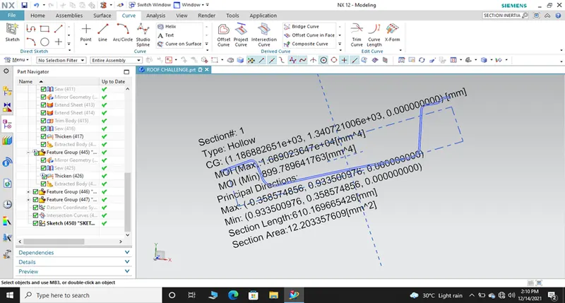
S= I/Y
I= 899.78 mm^4 * 10^3, Y= 433.84 mm
S= 2074 mm^3
BOW ROOF 1 RAIL
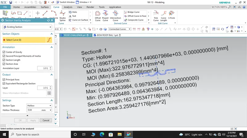
S= I/Y
I= 6.25 mm^4 * 10^3, Y= 324.3 mm
S= 19.29 mm^3
CENTER ROOF RAIL
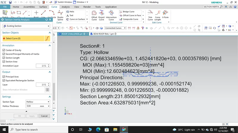
S= I/Y
I= 12.60 mm^4 * 10^3, Y= 387.11
S= 32.55 mm^3
BOW ROOF RAIL 2
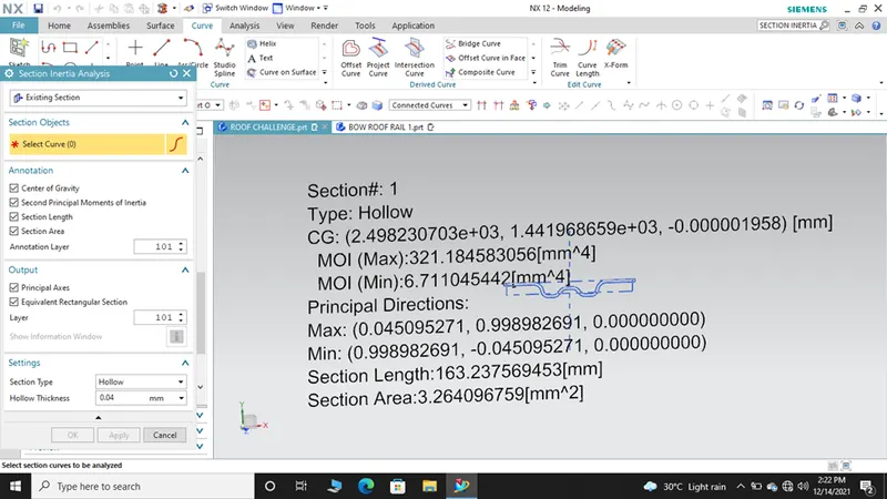
S= I/Y
S= 17.48 mm^3
REAR ROOF RAIL
S=I/Y
S= 1757 mm^3
CONCLUSION
The roof, front roof rail, bow roof rails, central roof rail and the rear roof rail is designed with reference to the master section provided. Also the moment of inertia, section modulus are identified as per the design requirements.