Roof challenge
Roof Design and Analysis of Reinforcements
Objectives:
Create a Car Roof model based on the styling surface, master sections given for various parts with mastic points and reinforcements. Determine whether the design is complying with Heat distortion criteria through curvature study on the roof. Judge the snowed condition criteria of the roof model using the prediction formula to conclude if the roof can withstand the load acting upon it. Prepare a section modulus study for roof parts Bow roof 1, Bow roof center, and Bow roof 2 in the OY section. Draft analysis of all the parts to check for tooling feasibility.
Introduction:
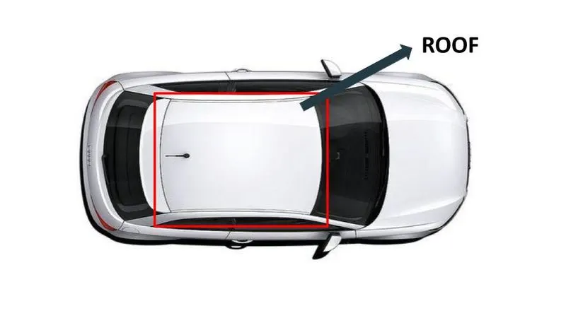
The roof is an important part of an automobile as it protects the occupants from various environmental conditions like Heat, Snow, Rain, and winds. There are many types of the roofwhich differs based on the variants of the car and the region. The roof must be designed in such a way that it would able to withstand any load or impact due to accidents or objects fallingon it and other environmental factors. So, the design done is based on the standards and design intent which makes the roof to withstand the above-said conditions. Also, other factors Headroom, aesthetics play a role in the design. The roof is an assembly of many parts like Front roof rail, Bow roof, Bow roof center, and reinforcement center. The number of bow roofs is based on the length of the roof and sometimes even the bow roof center is avoided in cases like small cars. The roof is attached to the body of the car using mastic sealants provided between bow roofs and the front and rear rails.
In later years, many variations on the automobile roof developed. These include:
Convertible roofs
Hardtops
Sunroofs
T-tops
Targa tops
Vinyl roofs
Convertible roofs
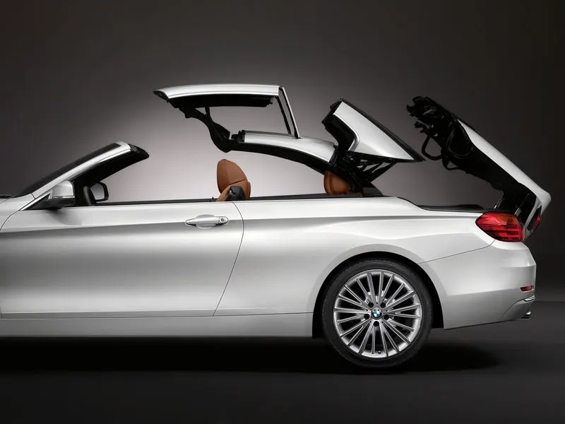
A convertible or cabriolet is a passenger car that can be driven with or without a roof in place. The methods of retracting and storing the roof vary between models. A convertible allows an open-air driving experience, with the ability to provide a roof when required. Potential drawbacks of convertibles are reduced structural rigidity (requiring significant engineering and modification to counteract the effects of removing a car's roof) and cargo space.
Hardtops
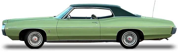
A hardtop is a rigid form of automobile roof, which for modern cars is typically constructed from metal. A hardtop roof can be either fixed (i.e. not removable), detachable for separate storing, or retractable within the vehicle itself.
Pillarless hardtop (often referred to as simply "hardtop") is a body style of cars without a B-pillar, which are often styled to give the appearance of a convertible design.
Sunroofs
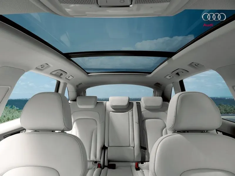
A sunroof is a movable panel that opens to uncover a window in an automobile roof, allowing light and fresh air to enter the passenger compartment. Sunroofs can be manually operated or motor-driven, and are available in many shapes, sizes, and styles. While the term sunroof is now used generically to describe any glass panel in the roof, the term "moonroof" was historically used to describe stationary glass panes rigidly mounted in the roof panel over the passenger compartment. A moonroof has a glass panel that is transparent and usually tinted. Previous terms include Sunshine Roof, Sliding Head, and Sliding Roof.
T-tops
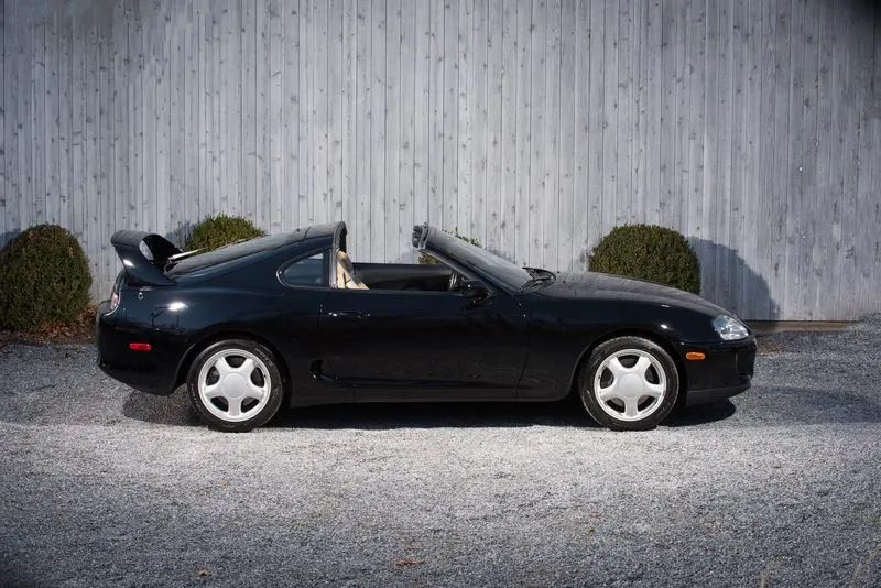
A T-top (UK: T-bar) is an automobile roof with a removable panel on each side of a rigid bar running from the center of one structural bar between pillars to the center of the next structural bar. The panels of a traditional T-top are usually made of auto-grade safety glass.
Targa tops
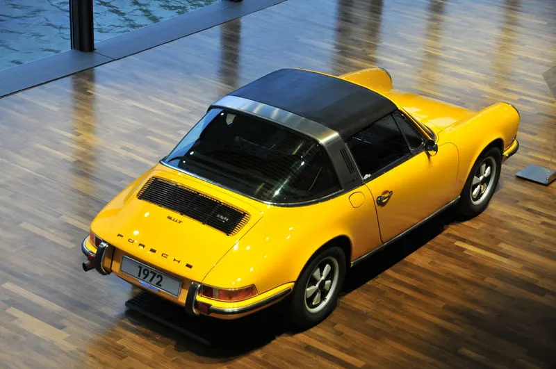
Targa top, or Targa for short, is a semi-convertible car body style with a removable roof section and a full-width roll bar behind the seats. The term was first used on the 1966 Porsche 911 Targa, and it remains a registered trademark of Porsche AG.
The rear window is normally fixed, but on some Targa models, it is a removable plastic foldable window, making it a convertible-type vehicle. Any piece of normally fixed metal or trim that rises up from one side, over the roof, and down the other side is sometimes called a Targa band, Targa bar, or a wrap-over band.
Targa tops are different from T-tops, which have a solid, non-removable bar running between the top of the windscreen and the rear roll-bar, and generally have two separate roof panels above the seats that fit between the window and central t-bar.
Vinyl roofs
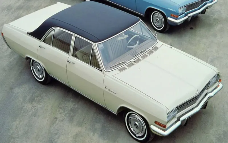
Vinyl roof refers to a vinyl covering for an automobile's top.
This covering was originally designed to give the appearance of a convertible to models with a fixed roof, but eventually, it evolved into a styling statement in its own right. Vinyl roofs were most popular in the American market, and they are considered one of the period hallmarks of 1970s Detroit cars. Vinyl roofs were also popular on European- (especially UK-) and Japanese-built cars during the 1970s and tended to be applied to sporting or luxury trim versions of standard saloon (sedan) models.
Front roof rail
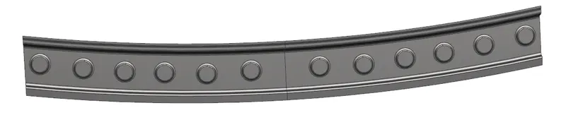
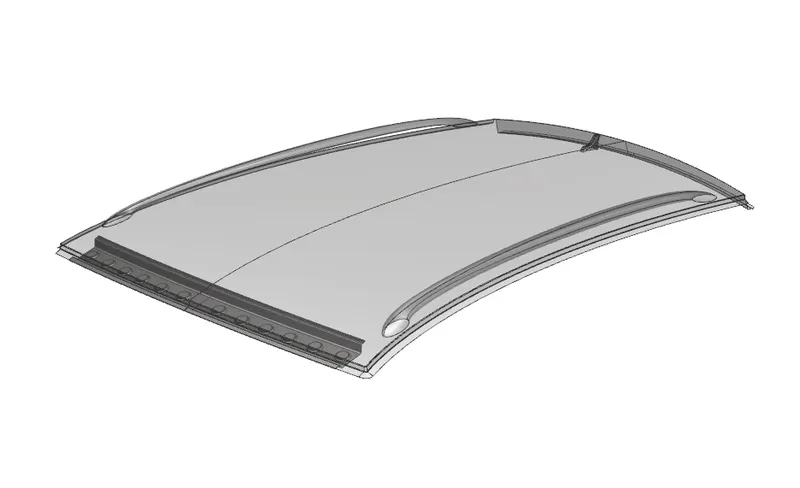
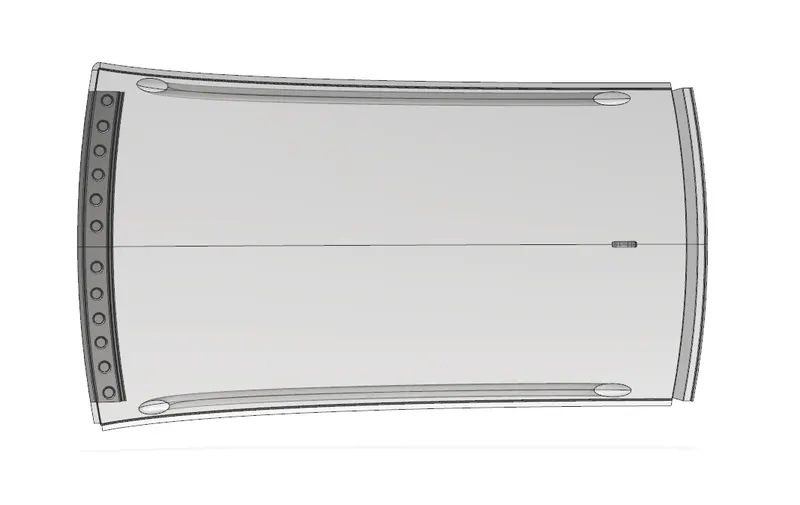
From dump solid part class A surface is extracted and ditch areas are developed considering the parameter specified in the following master section.
A flange of around 15mm was created with the law extension command, corner relief at rear flanges, and positive draft more than 3 degrees considering for the drawing operation process. The overall thickness of sheet metal considers 0.75mm throughout. It lies at the front part of the roof. It provides strength to the roof panel front. It is the support that is joined with the windshield glass, bodyside outer and inner panels. The draft angle of 3-5 degrees is provided keeping in mind of a deep-drawing operation. The bottom-most flange is designed by considering the headroom clearance and visibility criteria. Spot welds are applied at the windshield end of the rail and the other end is joined with the roof using mastic sealants which also contributes to increasing strength.
Bow roof Rail-1

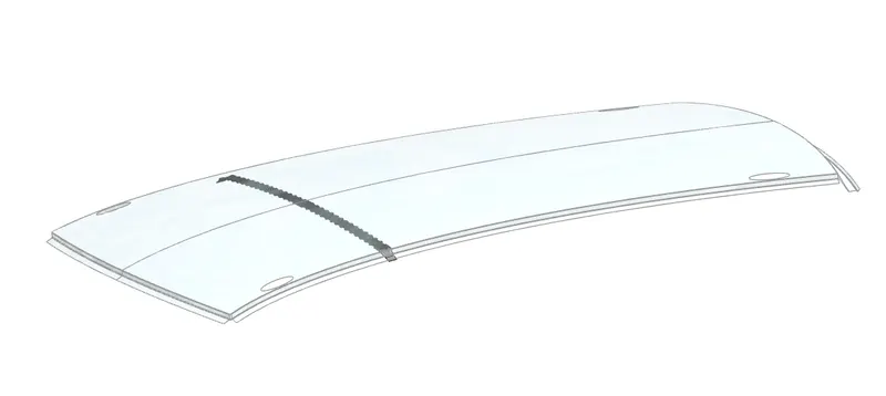
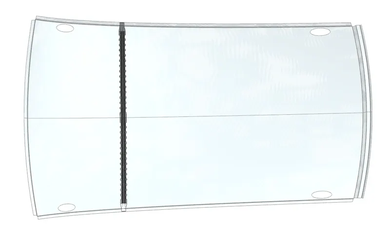
The bow roof rails provide additional support to the roof. They are positioned in such a way that they provide maximum support to the roof. They are designed in such a way that they do not intrude into the headroom requirement of the car. Bow roof rails are the additional features provided as per the requirement. Small cars may have no bow roof while large cars may have 2 or more. If there is a sunroof then the bow roof is integrated into the center roof rail. The roof is fixed to the bow roofs with the use of mastics while the ends are spot welded.
The Bow roofs are given to improve the torsional stiffness and load-bearing capacity of the roof structure. The number of bow roofs provided will depend upon the overall dimensions of the roof. The longer the roof more the bow roofs are integrated into the BIW frame They are attached to the outer panel using mastic sealants. Each mastic point will have up to 80 mm circular effective area. The positioning of bow roofs is done based on a curvature study. The heat distortion criteria and snow load criteria are checked to analyze the position of the cows in various conditions.
Bow roof Rail-2

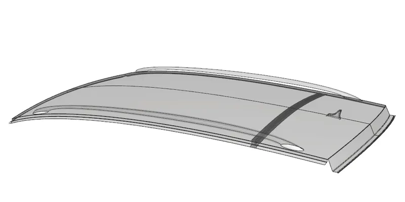
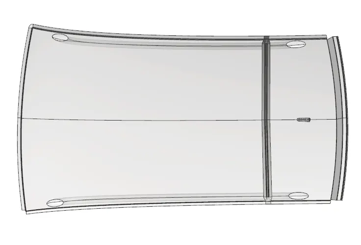
The Bow roofs are given to improve the torsional stiffness and load-bearing capacity of the roof structure. The number of bow roofs provided will depend upon the overall dimensions of the roof.
Mid Roof Rail
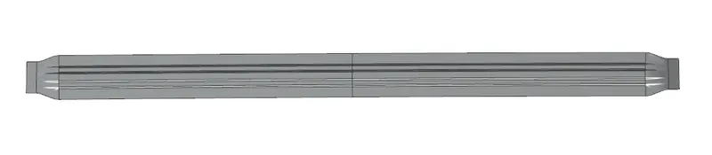
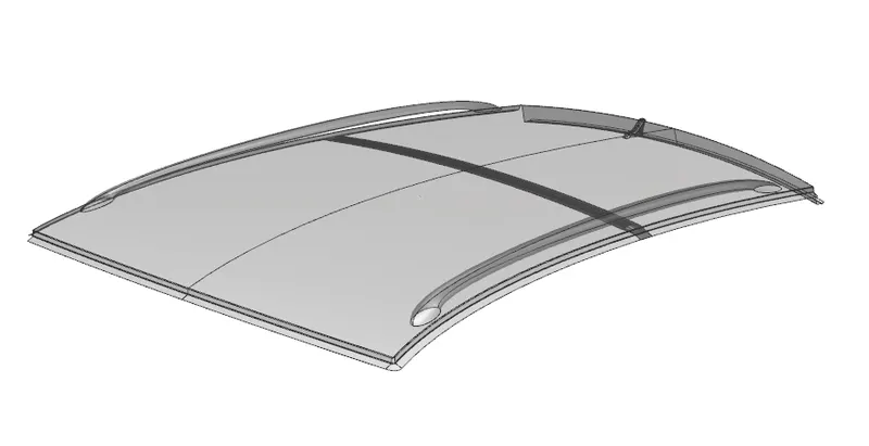
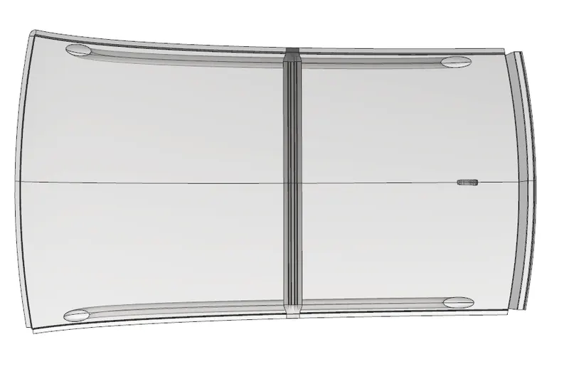
Back Roof rail
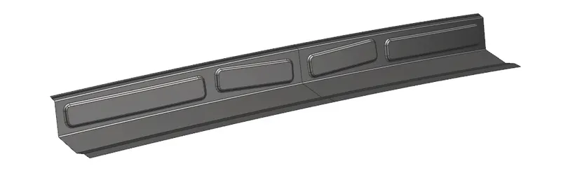
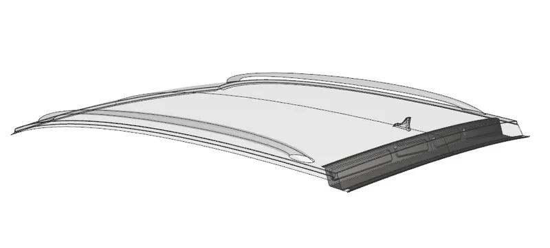
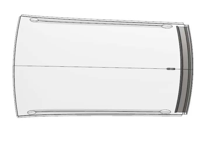
The surface is offset from the outer panel to form the ditch area and with the law extension command, corner relief at rear flanges, and positive draft in required degree considering for the drawing operation process. The overall thickness of sheet metal for the outer panel consider 0.75mm throughout.
It lies at the rear part of the roof. It provides strength to the roof panel rear. It is the support that is joined with the back door, bodyside outer and inner panels. The design consideration is the same as of the front roof rail but here inputs from the back door design are also taken into consideration to accommodate the required clearance. Spot welds are applied at the back door end of the rail and the other end is joined with the roof using mastic sealants.
Design Consideration for roof:
- Visibility criteria
- Headroom Clearance
- Curvature study
- Heat distortion test
- Snow load test
- Draft analysis
Visibility criteria:
Good all-round visibility is one of the main requirements of body design. Visibility depends on the window opening and its relative position to the occupants. If the occupant is placed close to the windscreen the forward visibility is considerably improved but comfortable entry is adversely affected as the dimension between pillar and seat is decreased requiring suitable shaping of the door, if possible. Downward visibility can be improved by positioning the driver as high as possible in relation to the lower edge of the windscreen. Rearward visibility is achieved by an increase in glass area required to maintain rearview vertical angle with back window. Figures below show the eye position of the driver, angle of visibility, and space between pillar and seat.
Headroom clearance:
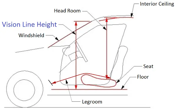
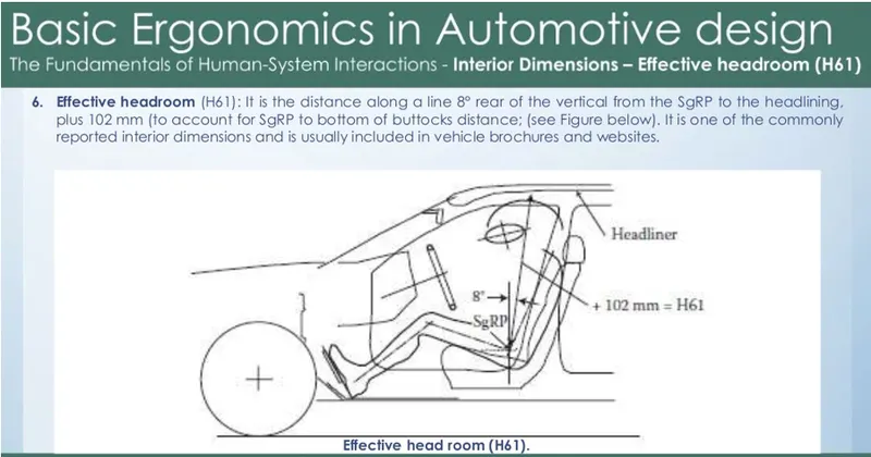
Headroom is measured as the distance from a car's roof to its seat bottom. A more appropriate name might be 'torso room. Sometimes there is maximum and minimum values published, since most cars have seats that adjust up and down.
Roof Crush Test:
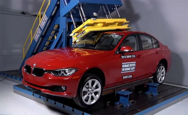
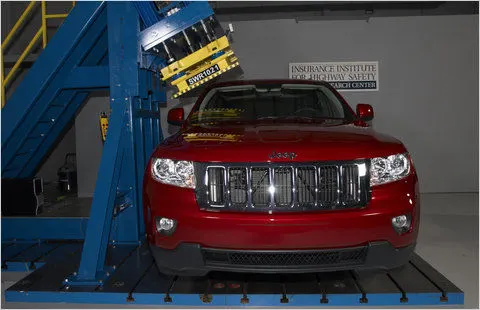
Roof crush is the failure and the displacement of an automobile roof into the passenger compartment during a rollover accident. To avoid this the Insurance Institute of Highway Safety introduce this 'Roof crush test. So after analyzing so many accidents IIHS has then fixed some regulations on how to perform the roof crush test.
Purpose of doing roof crush test:
A roof crush test is done to minimize the protrusion into the occupant compartment so that the seat belts and airbags can do their work properly. Features such as electronic stability control are proven to significantly reduce rollovers and lane departure warning systems may also help. Rollover sensing side curtain airbags also help to minimize injuries in the event of a rollover.
Conditions for roof crush test:
There are two conditions that are followed in the roof crush test. They are;
First condition:
• Close and lock all the doors
• Close all the windows
Second condition:
Fix the body sill or chassis frame on a hard lever surface horizontally.
Method of applying force:
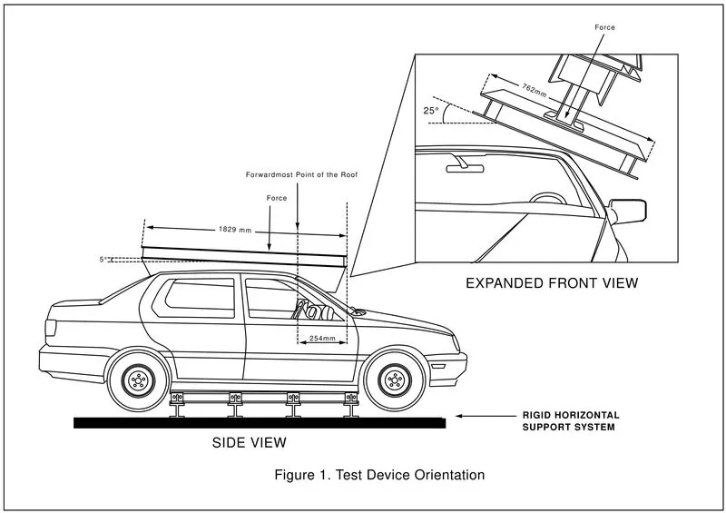
The load is applied in such a way that 5° is tilted to the front end from the rear end and the load will be applied in the 1800 mm in length and 750 mm in width. The load is applied at the position of 25 from the flatness of the roof down to the right side. The load is applied on the roof for almost 120 seconds and the crushing speed is 13mm/sec or less than that at which the load is applied.
Test results and improvement:
If the displacement goes above the required level then we have to increase the bow roof thickness or add more mastic points and embosses to increase the strength. The stronger the roof the better it can protect the occupants in the rollover crashes.
Heat distortion criteria:
Heat distortion temperature is the temperature at which materials soften and deforms under a specific load. This study is used to predict the heat distortion temperature at where the materials start to soften when exposed to a fixed load at elevated temperatures. In order to avoid bending or damages on the roof, base don heat distortion temperature, this study will predict the bow roof position which helps to strengthen the roof.
Bow-roof prediction Formula
W-[1.73 x 10^(-3) x L]+[1.85 x 10^(-8) x (R^2)/t]+[1.10x10^(-3) x 1] -2.68
Judgement Condition: OK< 2.7> 3.1
Where.
L-Roof Length in X-Direction [mm] (Roof dimension in 0-Y)
R=Roof curvature = 2(Rx*Ry)/(Rx+Ry)
Rx-X-curvature
Ry-Y-curvature
t=Roof plate thickness [mm]
1-Bow Roof span [mm]
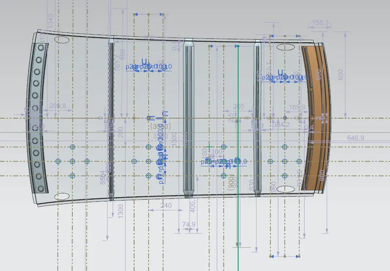
Steps to know the values for the above parameters:
1. First an OY line will be created at the center of the styling of the roof which would be in the horizontal direction.
2. Create a middle line between the roof rails and bow roofs and then make an offset of 100 mm with respect to this line in both directions.
3. An offset of -3Y (i.e. 300 mm) will be made below the horizontal line.
4. Again offset will be made from the above line which would be 100 mm above and below the line.
5.6 Intersection points will be made through the intersection of the lines.
6. These intersection points will be projected on the styling of the roof with the help of the project curve feature.
7. Arcs will be made by joining the three lines horizontally and vertically to obtain the Rx value along the X direction and the Ry value along the Y direction.
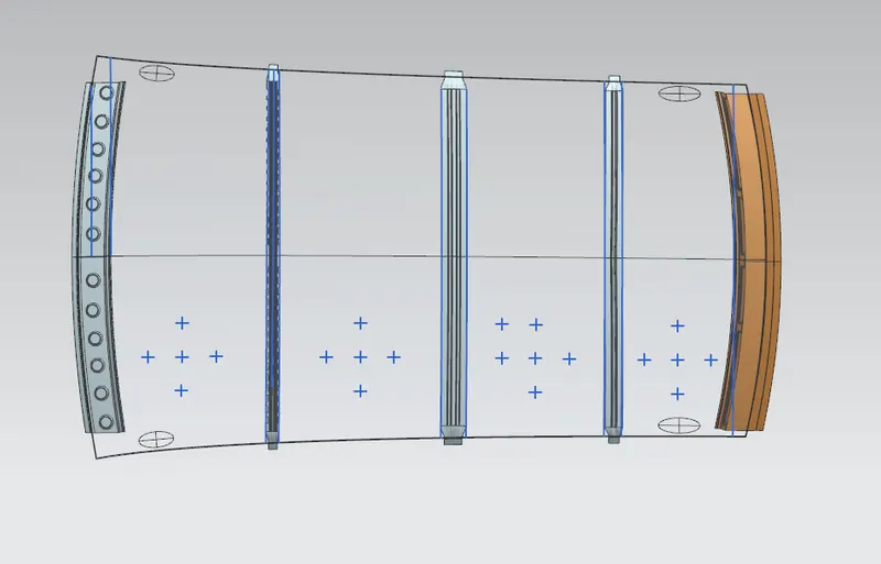
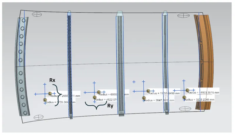
From the above data all the values can be obtained and hence the heat distortion criteria is calculated which is shown below:
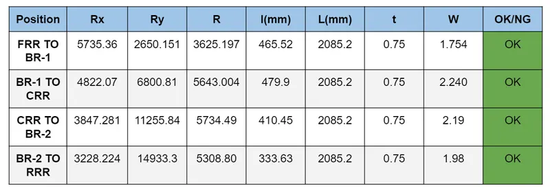
From the above calculations, we can conclude that the designed bow roofs and center roof rail are at the appropriate position and can easily withstand heat distortion.
Snow Load criteria:
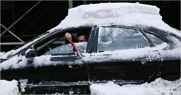
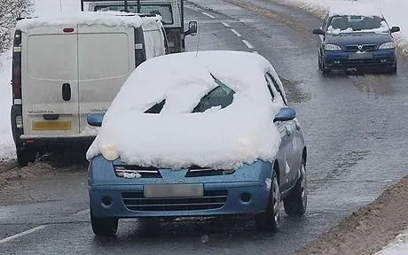
Snow load study is done to check the withstand ability when the snow loads over the roof during the winter season in snowfall regions. This study will also analyze that whether permanent deformation occurs after the removal of the snow load. So the roof is designed in such a way that if the snow load on the roof then it may bend but needs to be back in its original position after the removal of the snow load.
Snow load Prediction formula:
Qr- [ly xt¹]/[axsx [(Rx+ Ry)/2]² x 108
Where
a-My x Lx² x 10-¹2, My = Y(Ly-Y)
Judgment condition - Qr 23.1
250 SS ≤ 380
t-Roof plate thickness [mm]
Ly Distance between the front and rear roof Rails on the Vehicle along with OY[mm]
Length of Roof panel with the center point between Roof rail Front /Rear as the front and rear reference point.
Lx = Distance between the Left and Right end of the roof on the Roof BOW [mm]
The width of the roof panel is exposed on the surface.
Y-Distance front Front Roof Rail to Roof BOW[mm]
s Distance for which Roof BOW bears divided load [mm]
s-L1/2 L2/2
ly - Geometrical moment of inertia of Roof BOW (Y cross-section )[mm4]
The rx-Lateral direction curvature radius of roof panel Y cross-section on Roof BOW [mm]
Roof panel curvature Radius of the Length Lx in Front view
Ry Longitudinal Direction curvature radius of the Roof panel X cross-section on Roof BOW. [mm]
Roof panel X curvature radius of lengths in Side view
Steps to know the values for the above parameters:
1. The first step is to create the OY line considering the styling surface of the roof in the horizontal direction. The length of this line will give Ly value.
2. Now the Ly line needs to be offset with a distance of 100 mm in both the direction.
3. Middle line needs to be made between each reinforcement to obtain the Lx value.
4. With the help of the middle line offset lines are created which will be 100 mm apart on both sides.
5. Now intersection points will be generated through the intersection of the lines that we created.
6. Now these points will be projected on the styling of the roof surface.
7. Arcs will be drawn by attaching the three points together to obtain the Rx and Ry values.
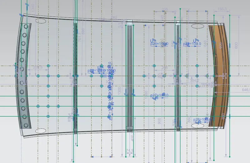
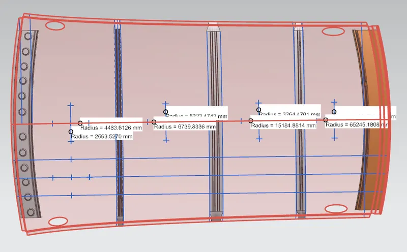
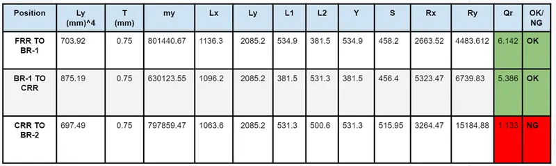
From the above table, we can observe that the snow load condition is not satisfying in the region between the center roof rail and the bow roof 2 as the value of Qr should be greater than or equal to 3.1
Solution for the above case:
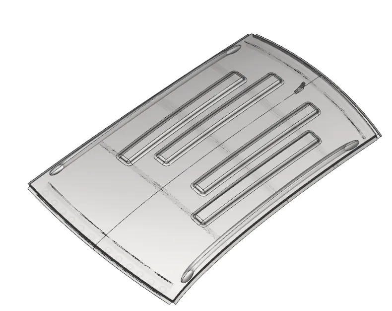
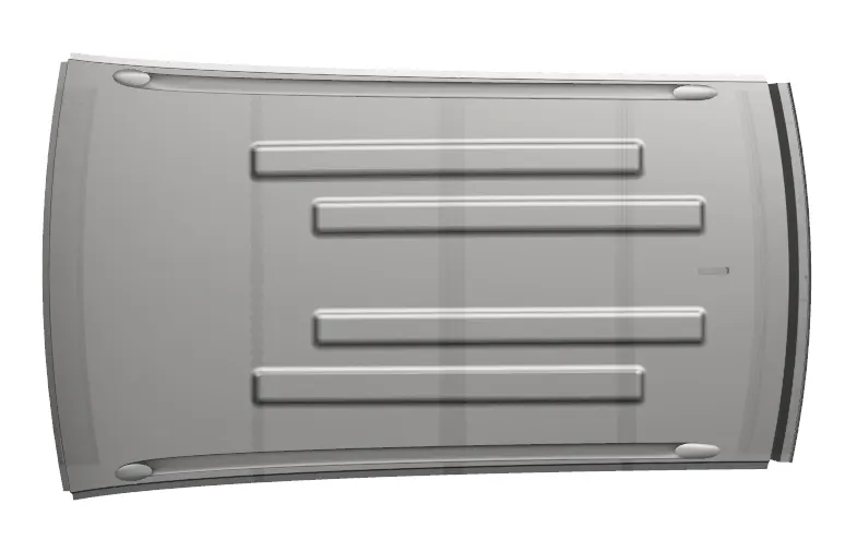
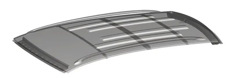
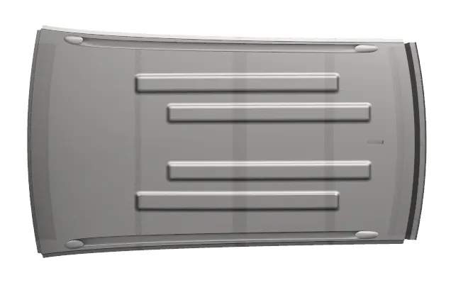
For solving the above problem in the region between the Center roof rail and bow roof embosses will be made on the outer roof in order to provide strength to the roof so that the roof can withstand the snow load condition.
The modified roof with embosses is shown below:
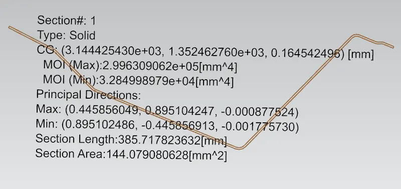
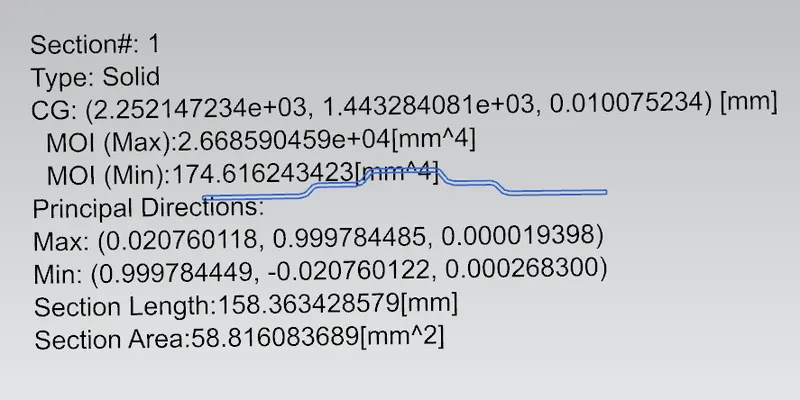
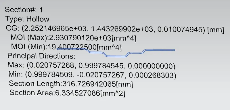
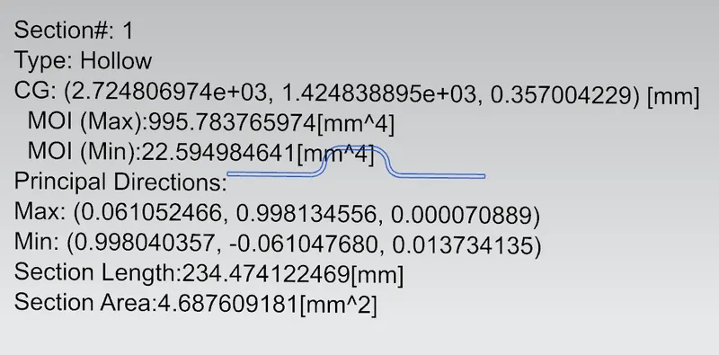
Section Modulus:
Section modulus is a geometric property for a given cross-section used in the design of beam or flexural members. It is termed as the ratio of moment of inertia and the distance from the neutral axis to the extreme edge.
It is given by
S=I/Y
Where,
1- Moment of inertia
Y-Distance from the neutral axis to the extreme edge
Back Roof rail
Mid Roof Rail
Bow roof Rail-2
Draft Analysis:
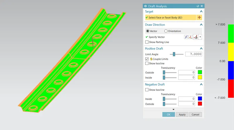
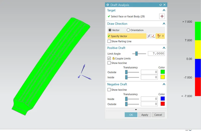
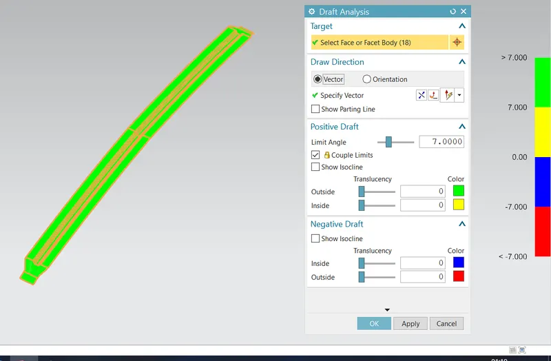
Before sending the design to the manufacturing team draft analysis is done in order to check if the part can be easily removed or not. This type of analysis is done based on the color ranges identifying zones on the analyzed element where the deviation from the draft direction at any point, corresponds to specified values.
A minimum angle of 7 degrees is considered for the analysis. Green color infer on the parts that all face along the tooling direction has a positive draft angle greater than 7 degrees and passed in analysis
Front roof rail
Back Roof rail
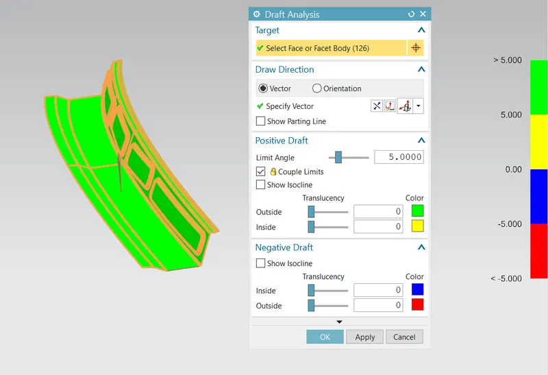
We can notice few negative drafts in the above part. the negative drafts are in the embosses . we can remove the negative draft by making changes in the draft angle of emboss.
we can also remove the negative draft by changing the orientation of the tool direction.
Mid Roof Rail
Bow roof Rail-2
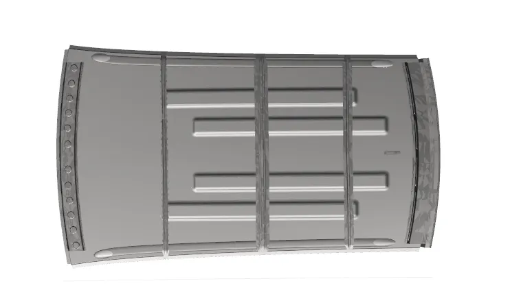
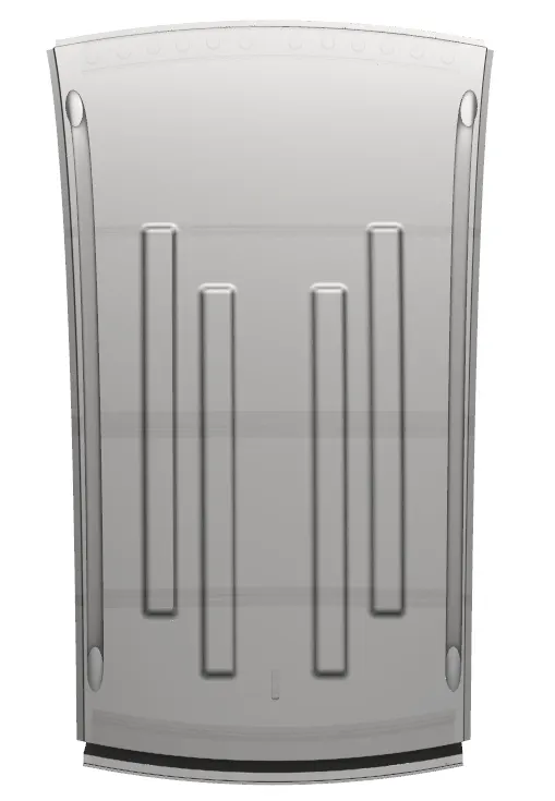
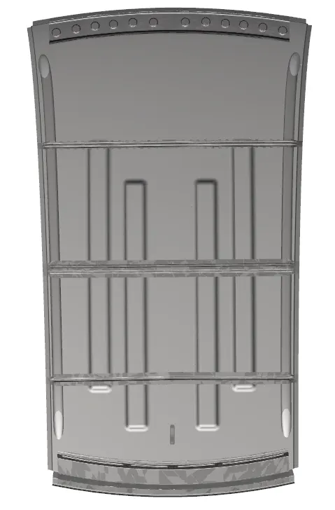
Different views of the Roof
CONCLUSION
1. The roof and the reinforcements were designed as per requirements by placing them at required positions.
2. Ditch Area is designed along the edges of the roof.
3. Draft analysis was performed on each component.
4. Section Modulus is calculated for each reinforcement.
5. Curvature stud of the roof is performed and it was observed that the design passed the heat distortion criteria, but the snow load criteria could not be cleared in the region between center roof rail and bow roof 2.
6. To fix this solution either one of the solutions can be performed.
- This will be notified to the styling team to improve the curvature in this region to improve the strength at this place, if this is not accepted by the styling team,
- Embosses on the roof can be designed to improve the strength in this region.