Roof challenge
AIM
To create and assemble the roof front rail, rear rail, bow rails and their reinforcements by following the design rules and master section.
SOFTWARE USED
SIEMENS NX CAD 12
OBJECTIVES
- For the Given Roof styling, Develop the essential flanges and reinforcements, Provide appropriate dimensions and check for Draft analysis, and submit your Section Inertia report on the 0-Y section.
- Start with the creation of a roof ditch area the tool opening angle is only 3 degrees.
- Do a curvature study on the roof and perform calculations to determine the position of the Bow-roof
INPUT DATA
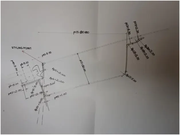
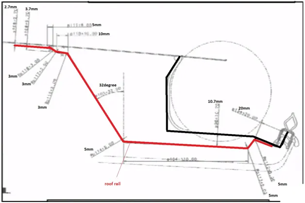
ROOF
An automobile roof or car top is the portion of an automobile that sits above the passenger compartment, protecting the vehicle occupants from sun, wind, rain, and other external elements. Because the earliest automobiles were designed in an era of horse-drawn carriages, early automobile roofs used similar materials and designs.
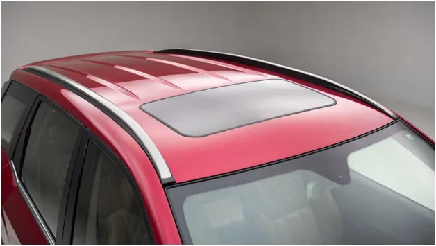
TYPES OF ROOF
- Convertible roofs
- Hardtops
- Sunroofs
- T-tops
- Targa tops
- Vinyl roofs
SAFETY CONSIDERATION
In a vehicle rollover accident, the strength of the roof structure is an important factor of security in order to reduce the death and injury rates. The National Highway Traffic Safety Administration proposed strength requirements of the roof structure on roof crush resistance in the Federal Motor Vehicle Safety Standard (FMVSS) 216. Recently, there have been many structural optimization studies that design the structure of a vehicle to satisfy this safety regulation. Most previous studies used approximation methods such as the response surface method (RSM) as a crash problem has high non-linearity and difficulty in sensitivity calculation. However, the solution from the RSM may not be accurate and has a limit on the number of design variables. In this research, non-linear dynamic (transient) response optimization using equivalent static loads (ESLs) is proposed to design the structure of a vehicle to satisfy the safety regulation. ESLs for linear response analysis are made to generate the same displacement field as that from non-linear dynamic loads at each time step of non-linear dynamic analysis. A dynamic load is transformed to a set of ESLs. The static loads are used as the multiple loading conditions for linear response optimization, which are not costly in the linear response optimization process. Size optimization using ESLs is performed to reduce the structural mass while the FMVSS 216 regulation is satisfied. The optimum results using ESLs are compared with those from the RSM.
Federal Motor Vehicle Safety Standard (FMVSS) 216.
First, for the vehicles currently subject to the standard, i.e., passenger cars and multipurpose passenger vehicles, trucks and buses with a Gross Vehicle Weight Rating (GVWR) of 2,722 kilograms (6,000 pounds) or less, the rule doubles the amount of force the vehicle's roof structure must withstand in the specified test, from 1.5 times the vehicle's unloaded weight to 3.0 times the vehicle's unloaded weight. Second, the rule extends the applicability of the standard so that it will also apply to vehicles with a GVWR greater than 2,722 kilograms (6,000 pounds), but not greater than 4,536 kilograms (10,000 pounds). The rule establishes a force requirement of 1.5 times the vehicle's unloaded weight for these newly included vehicles. Third, the rule requires all of the above vehicles to meet the specified force requirements in a two-sided test, instead of a single-sided test, i.e., the same vehicle must meet the force requirements when tested first on one side and then on the other side of the vehicle. Fourth, the rule establishes a new requirement for maintenance of headroom, i.e., survival space, during testing in addition to the existing limit on the amount of roof crush. The rule also includes a number of special provisions, including ones related to leadtime, to address the needs of multi-stage manufacturers, alterers, and small volume manufacturers.
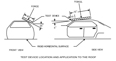
DESIGNING OF ROOF RAILS
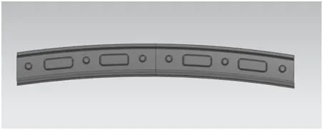
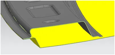
FRONT ROOF RAIL
- The front roof rail is created at the front side of the roof.
- The factors should consider while designing the roof are headroom clearance and visibility criteria
- While designing the front roof the visibility of driver and passenger should be clear.
- Small changes in dimension will lead to changes in visibility criteria
BOW ROOF RAIL
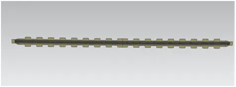
- The creation of bow roof is to give more strength of the roof
- The number of roof is depends upon the length of the roof
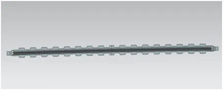
- The centre bow roof will created on the centre of the reinforcement.
- Mastic seal is provided to connect the roof and bow roofs.
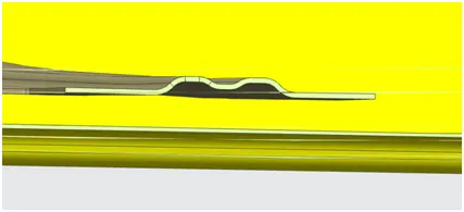
- 5mm gape is maintained for mastic seal paste between outer panel and bow roof
BOW ROOF RAIL
CENTRE BOW ROOF
REAR ROOF RAIL
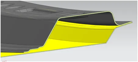
- The front roof rail is created at the Rear side of the roof same like front
- The factors should consider while designing the roof are headroom clearance and visibility criteria
- While designing the front roof the visibility of driver and passenger should be clear.
- Small changes in dimension will lead to changes in visibility criteria
CENTRE ROOF
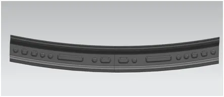
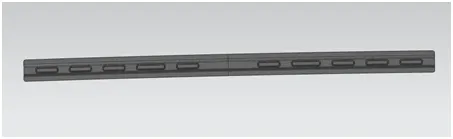
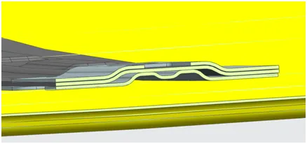
- Centre Reinforcement is created at the centre of the roof.
- The purpose of reinforcement is to give more strength to roof and also for extra reinforcements created for car indoor light.
- The reinforcement is attached to centre bow roof by using mastic seal
HEAT DISTORTAION STUDY ON THE ROOF
The heat distortion study plays a major role in sheet metal usage. Heat distortion temperature is a temperature limit above which the material cannot be used for the structural applications. This study is used to predict the heat distortion temperature at where the material starts to soften, when exposed to a fixed load at elevated temperature. In order to avoid bending or damages on the roof, based on the heat distortion temperature, this study will predict the bow roof position which helps to strengthen the roof.
Bow-Roof Prediction Formula:
W= [1.73x10^(-3) x L]+[1.85x10^(-8) x (R^2)/t] + [1.10x10^(-3) xI ]-2.68
Judgement Condition: OK< 2.7> 3.1
Where,
L= Roof Length in X-Direction[mm] (Roof dimension in O-Y)
R= Roof curvature
R = 2(Rx*Ry)/(Rx+Ry)
Rx = X curvature
Ry = Y curvature
t = Roof plate thickness [mm]
I= Bow Roof Span [mm]
HEAT DISTORTAION TABLE
|
S.NO |
POSITION |
Rx |
Ry |
R |
I |
L |
t |
R^2/t |
W |
RES |
|
1 |
FR&BR1 |
5468.25 |
2464.91 |
3398.08 |
505 |
2033.55 |
0.75 |
15395930.3 |
1.678 |
OK |
|
2 |
BR1&CR |
4388.43 |
6410.06 |
5210.45 |
488 |
2033.55 |
0.75 |
36198385.6 |
2.044 |
OK |
|
3 |
CR&BR2 |
2986.83 |
7069.87 |
4199.49 |
432 |
2033.55 |
0.75 |
23514288.4 |
1.748 |
OK |
|
4 |
BR2&RR |
3096.24 |
14584.69 |
5108.07 |
543 |
2033.55 |
0.75 |
26092379.1 |
1.918 |
OK |
*The above table all the dimensions are in mm
W is passing in all load condition; hence heat distortion for above roof is cleared
SNOW LOADCRITERIA
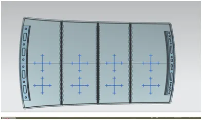
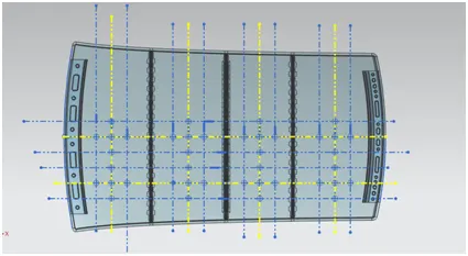
Snow load criteria is useful to justify the bow roof rail position in snow fall regions. Due to snow fall snow will get collected on the top roof which will tend to bend the roof. Bow roof will be at such position which will provide more strength to roof against bending.
Snow load Prediction Formula:
Qr = [Iy x t2] / [α x s x [(Rx + Ry)/2]2 x 10-8]
Note: The Qr value given over here is correct. There was a typo error in the formula given in the video.
Where
α = My x Lx2 x 10-12 , My = Y(Ly-Y)
Judgement condition = Qr ≥ 3.1
250 ≤ s ≤ 380
t = Roof plate thickness [mm]
Ly = Distance between the front and rear roof Rails on the Vehicle along with 0Y[mm]
Length of Roof panel with the center point between Roof rail Front /Rear as the front and rear reference point.
Lx = Distance between the Left and Right end of the roof on the Roof BOW [mm]
Width of the roof panel exposed on the surface.
Y = Distance front Front Roof Rail to Roof BOW[mm]
s = Distance for which Roof BOW bears divided load [mm]
s = L1/2 + L2/2
Iy = Geometrical moment of inertia of Roof BOW (Y cross-section )[mm4]
Rx = Lateral direction curvature radius of roof panel Y cross-section on Roof BOW [mm]
Roof panel curvature Radius of the Length Lx in Front view
Ry = Longitudinal Direction curvature radius of the Roof panel X cross-section on Roof BOW [mm]
Roof panel X curvature radius of length s in Side view
SNOW LOAD DISTORTION TABLE :
|
POSITION |
Iy |
L1 |
L2 |
Ly |
Lx |
Rx |
Ry |
t |
Y |
S |
My |
α |
Qr |
Res |
|
FR&BR1 |
23.55 |
505 |
488 |
2033.55 |
1137 |
4564.80 |
2516.80 |
0.75 |
505 |
496.5 |
771917.75 |
0.9979 |
0.2132 |
NG |
|
BR1&CR |
155.585 |
488 |
432 |
2033.55 |
1081 |
3775.14 |
4496.15 |
0.75 |
488 |
460 |
754228.4 |
0.8814 |
1.2622 |
NG |
|
CR&BR2 |
17.704 |
432 |
543 |
2033.55 |
1064 |
3508.53 |
10242.22 |
0.75 |
432 |
487.5 |
691869.6 |
0.7832 |
0.0551 |
NG |
|
BR2&RR |
7.756x10^3 |
543 |
0 |
2033.55 |
1043 |
3072.09 |
11774.60 |
0.75 |
543 |
271.5 |
809368.65 |
0.8804 |
33.122 |
No L2 value |
From the above table,
First ,second and third cases won't satisfy the conditions,all the Qr values is less than 3.1.fourth case there is no L2 value.
SECTION MODULUS
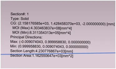
Section modulus (S) is a geometric property for a given cross-section used in the design of beams or flexural members.
The section modulus of the cross-sectional shape is of significant importance in designing beams. It is a direct measure of the strength of the beam. A beam that has a larger section modulus than another will be stronger and capable of supporting greater loads.
It is known that the stress in a fibre is proportional to its distance from the neutral axis. If y is the distance of the extreme fibre from neutral axis then. Here, S represents Section modulus or Modulus of section
S = I / y
SECTION MODULUS FOR OUTERPANEL
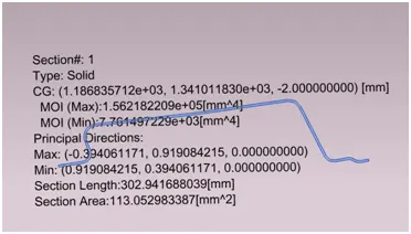
SECTION MODULUS FOR FRONT RAIL
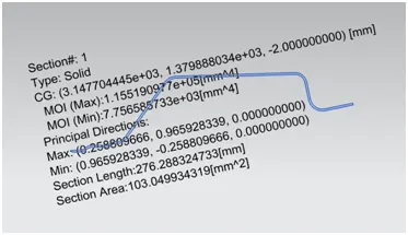
SECTION MODULUS FOR REAR RAIL
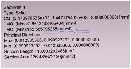
SECTION MODULUS FOR CENTRE ROOF
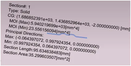
SECTION MODULUS FOR BOW ROOF 1
SECTION MODULUS FOR BOW ROOF 2
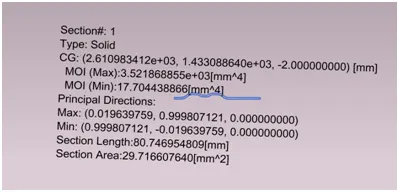
SECTION MODULUS TABLE :
|
S.NO |
MAXIMUM INERTIA(mm^4) |
MINIMUM INERTIA(mm^4) |
Y(mm) |
SECTION MODULUS(mm^3) |
|
OUTERPANEL |
4.30x10^8 |
8.31x10^5 |
1039.88 |
4130509.251 |
|
FRONT RAIL |
1.5621x10^5 |
7.76x10^3 |
56.25 |
2777.06 |
|
REAR RAIL |
1.155x10^5 |
7.756x10^3 |
57.49 |
2009.04 |
|
CENTRE ROOF |
2.8612x10^4 |
155.585 |
25.34 |
1129.12 |
|
BOW ROOF 1 |
5.94x10^3 |
23.55 |
22.75 |
261.098 |
|
BOW ROOF 2 |
3.521x10^3 |
17.704 |
18.995 |
185.364 |
DRAFT ANALYSIS
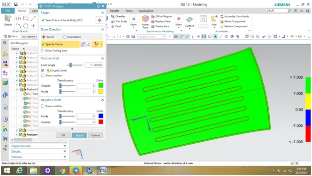
Draft Analysis is done to check whether the part is manufacturable or not. The minimum draft angle is to maintain for sheet metal is 7 mm. The tooling direction for the analysis is perpendicular to the designed part.
DRAFT ANALYSIS FOR FRONT ROOF
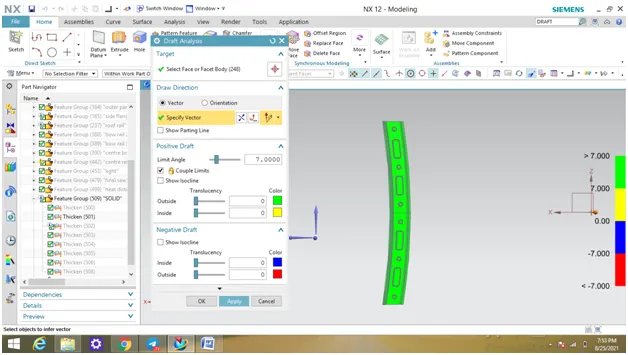
DRAFT ANALYSIS FOR REAR ROOF
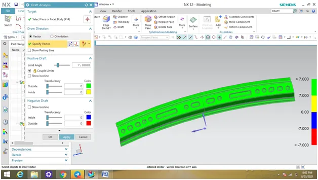
DRAFT ANALYSIS FOR CENTRE ROOF
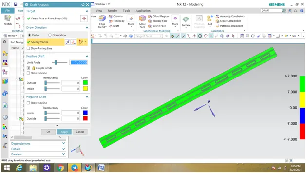
DRAFT ANALYSIS FOR BOW ROOF CENTRE
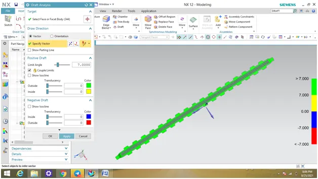
DRAFT ANALYSIS FOR LIGHT REINFORCEMENTS
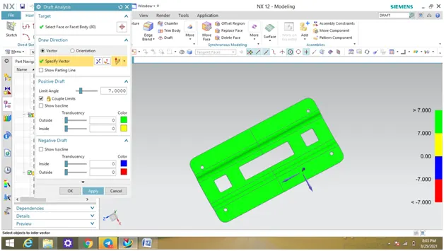
DRAFT ANALYSIS FOR BOW ROOF 1
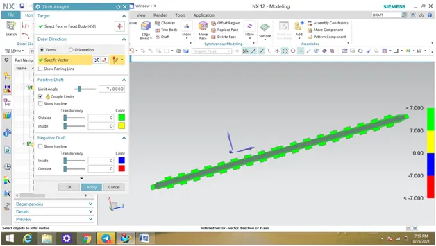
DRAFT ANALYSIS FOR BOW ROOF 2
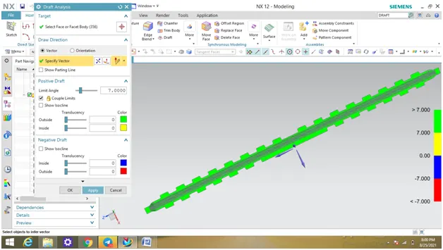
DRAFT ANALYSIS ON OUTER PANEL
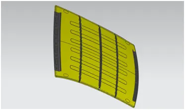
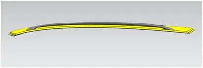
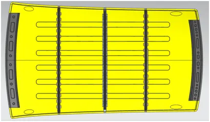
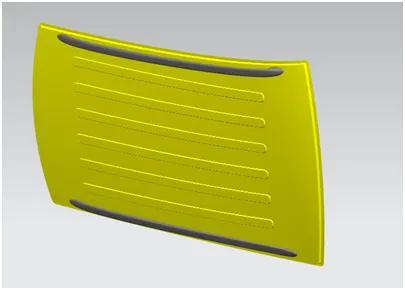
ROOF VIEWS
CONCLUSION
Thus the roof front rail, rear rail, bow rails and their reinforcements has created by following the design rules and master section.