Roof challenge
CAR ROOF
OBJECTIVE :
Design a car roof following the draft analysis on tool direction and also satisfy the bow roof prediction and snow load prediction
INTRODUCTION:
Car roof is the portion of an automobile that sits above the passenger compartment, protecting the vehicle occupants from sun, wind, rain, and other external elements. Bow roofs and center reinforcement are added to increase the strength of the roof.
ROOF DESIGN:
The automobile roof design consist of following parts Outer panel, Bow roof-1, Bow roof-2, Center reinforcement, Bow roof-3, Front roof rail and Rear roof rail in order.
The parts are designed following the draft angle to satisfy the tool direction accordingly.
Bow roof are made according to car length in this design we are made bow roof-1,2,3 and center reinforcement to increase the strength of the roof.After designing the entire part they all are thicken with 0.75mm.
Front roof rail front end and rear roof rail rear end are connected to roof by welds and remaining joins are done by mastic sealants to maintain styling of the roof.
FRONT ROOF RAIL:
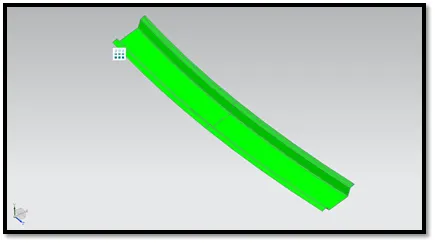
Front roof rail are designed from offsetting surface of top roof. Draft analysis conducted for front roof rail part with draft angle of 3,6,7 degree and the part passed the analysis test.One end is connected by welding method and other end connecting with top roof surface are connected with mastic sealants to maintain styling of the part.Where windshield cover from outer and console cover the welded part from inside to maintain styling .
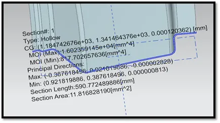
Moment of Inertia are also calculated for the part
- MOImin = 1.602359145e+04 mm^4
- MOImax = 817.702657636 mm^4.
DRAFT ANALYSIS
MOI CALCULATION
BOW ROOF 1:
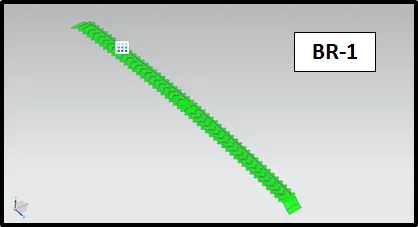
Bow roof-1 are designed from offsetting surface of top roof, side flange are connected with studio surface, law extension and trim & extend commands. Emboss are added for strengthening the part.Weld cannot be applied to this part to connect with roof as it affect the styling for the car so some design are made to apply mastic sealants.Draft analysis conducted for Bow roof-1 part with draft angle of 3,6,7 degree and the part passed the analysis test.Both end of the part are connected to the top roof by mastic sealants where spot weld cannot be applied here.
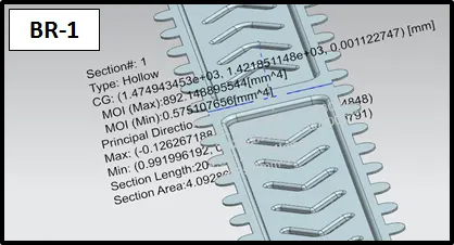
Moment of Inertia are also calculated for the part
- MOImin = 892.148895544 mm^4
- MOImax = 0.57510765600 mm^4.
DRAFT ANALYSIS
MOI CALCULATION
BOW ROOF 2:
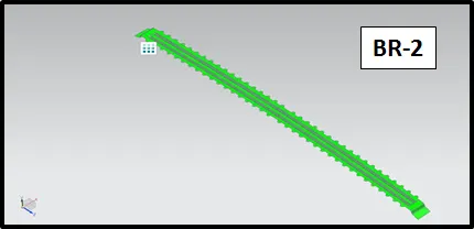
Bow roof-2 are designed from offsetting surface of top roof, side flange are connected with studio surface, law extension and trim and extend. Emboss are added for strengthening the part.
Weld cannot be applied to this part to connect with roof as it affect the styling for the car so some design are made to apply mastic sealants.Draft analysis conducted for Bow roof-2 part with draft angle of 3,6,7 degree and the part passed the analysis test. Both end of the part are connected to the top roof by mastic sealants where spot weld cannot be applied here.
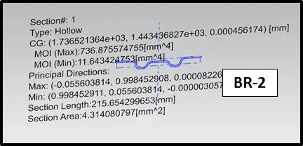
Moment of Inertia are also calculated for the part
- MOImin = 736.875574755 mm^4
- MOImax = 11.6434247530 mm^4
DRAFT ANALYSIS
MOI CALCULATION
REINFORCEMENT CENTER :
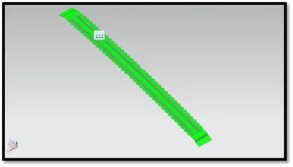
Reinforcement center are designed from offsetting surface of top roof and emboss are added for strengthening the roof.Weld cannot be applied to this part to connect with roof as it affect the styling for the car so some design are made to apply mastic sealants.Draft analysis conducted for Bow roof-1 part with draft angle of 3,6,7 degree and the part passed the analysis test.Both end of the part are connected to the top roof by mastic sealants where spot weld cannot be applied here.
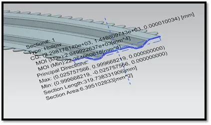
Moment of Inertia are also calculated for the part
- MOImin = 2.949922637e+03 mm^4
- MOImax = 22.254960618 mm^4
DRAFT ANALYSIS
MOI CALCULATION
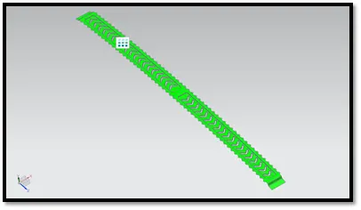
BOW ROOF 3:
Bow roof-2 are designed from offsetting surface of top roof, side flange are connected with studio surface, law extension and trim and extend. Emboss are added for strengthening the part.Weld cannot be applied to this part to connect with roof as it affect the styling for the car so some design are made to apply mastic sealants.Draft analysis conducted for Bow roof-3 part with draft angle of 3,6,7 degree and the part passed the analysis test.Both end of the part are connected to the top roof by mastic sealants where spot weld cannot be applied here.
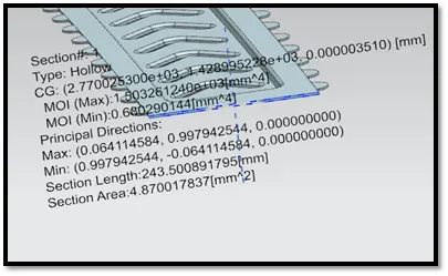
Moment of Inertia are also calculated for the part
- MOImin = 1.503261240e+03 mm^4
- MOImax = 0.680290144 mm^4.
DRAFT ANALYSIS
MOI CALCULATION
REAR ROOF RAIL:
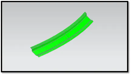
Rear roof rail are designed from offsetting surface of top roof. Draft analysis conducted for front roof rail part with draft angle of 3,6,7 degree and the part passed the analysis test. One end is connected by welding method and other end connecting with top roof surface are connected with mastic sealants to maintain styling of the part. Where windshield cover from outer and console cover the welded part from inside to maintain styling.
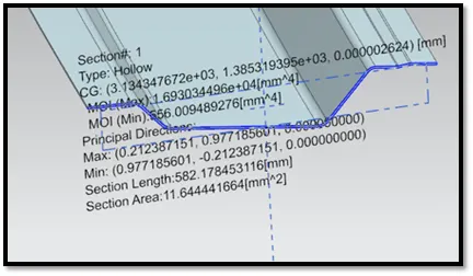
vMoment of Inertia are also calculated for the part
- MOImin = 1.693034496 e+04 mm^4
- MOImax = 556.009489276 mm^4.
DRAFT ANALYSIS
MOI CALCULATION
TOP ROOF:
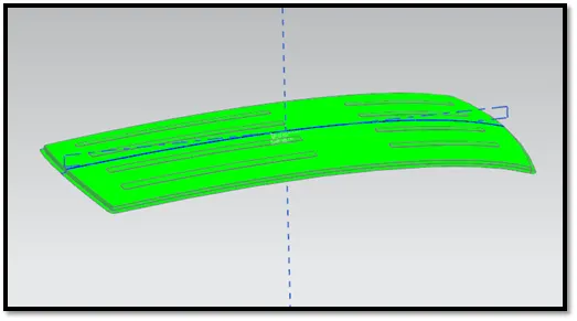
Top roof are designed by extending surfaces and filleting. Draft analysis conducted for front roof rail part with draft angle of 3,6,7 degree and the part passed the analysis test.
Moment of Inertia are also calculated for the part
- MOImin = 1.693034496 e+04 mm^4
- MOImax = 556.009489276 mm^4.
DRAFT ANALYSIS
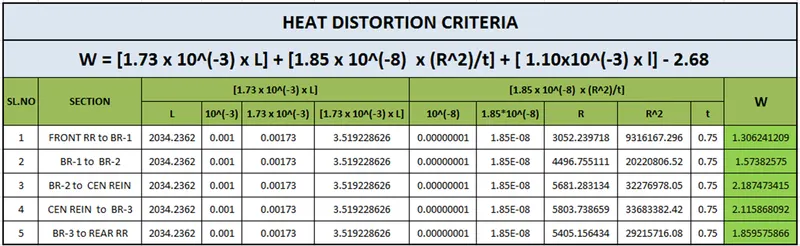
HEAT DISTORTION CRITERIA :
The calculated heat distortion criteria for our designed roof W value are less than 2.7 which passes the test.
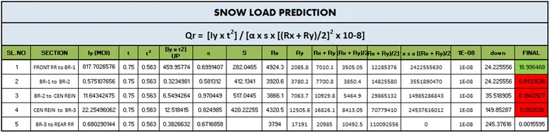
SNOW LOAD PREDICTION :
The calculated value should be greater than 3.1 which are highlighted in green where lesser value is taken for NG which is highlighted in red color. In this design the calculated value between front rail and bow roof-1 are passed remaining are NG.
JUSTIFICATION :
The design of the roof must be modified to achieve the requirement. In order to do that there are multiple ways to do it.
Condition 1: Changing Bow roof design to improve MOI the value change will meet the requirement
Condition 2: Changing Bow roof position where the RX RY LX LY changed final value will change and meet the requirement.
Condition 3: Adding emboss to the surface of roof without changing Bow roof position and design where the final value will change and meet the requirement.
We will implement condition3 scenario here adding emboss to increase the strength of the roof.
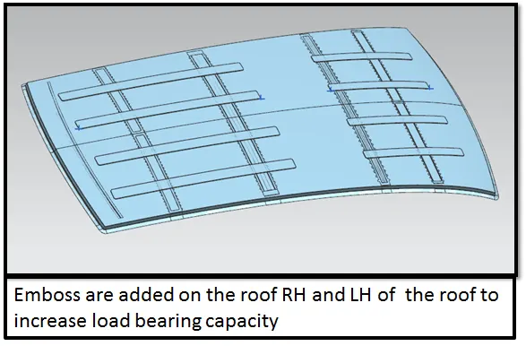
CONCLUSION:
The roof assembly that designed in are made with draft angle that is feasible for production. Another few studies are done to justify the bow roof positions and load bearing capacity of the roof like heat distortion criteria and snow load prediction. Designed part passed all the observation done for heat distortion criteria. In some observation of snow load prediction the part does not meet the requirement. After considering multiple way to increase the strength of the roof without changing the bow roofs distance and design we have added emboss to roof to increase strength and justified.