Rising Bubble Simulation Using Ansys Fluent
Aim: The major objective of this project is to set up the transient simulation using Ansys Fluent and Observe the behaviour of Bubble under Buoyancy force in the different fluid mediums along with the velocity of bubbles.
Introduction:
The changes in the behaviour of bubbles that rise in different liquids are peculiar for scientists. Many liquids and materials do not follow the Newtonian behaviour as they change their viscosities affecting the movement of particles within them based on the stress which is applied.
The application of the bubbles which rise in liquids can be seen when in a wide range of advanced engineering applications and used as a multiphase reactor in many industries, and when different processes are implemented such as in petrochemicals, the environment etc.
The experiments conducted on the movement of bubbles have been theoretical, practical and even numerical to understand this concept in depth.
The major objective of this project was to set up the transient simulation and analyze the behaviour of rising bubbles under the buoyancy effect using computational fluid dynamics in the Ansys-Fluent CFD package.
Multiphase flow Engineering is a very important topic of interest when we want to analyse different phases with different states or phases. Phases can be a combination of solid, liquid or gas.
There are three types of interphase in Multiphase engineering:
1. Separated Phase
2. Mixed Phase
3. Dispersed Phase
Earlier black-box approach model did not provide information about flow visualization.

There are many flow regimes that can be seen in multiphase flow engineering.
The details of different flow regimes are represented in the flow regime map for various setup of control parameters but for a specific problem.
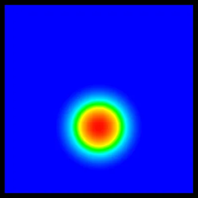


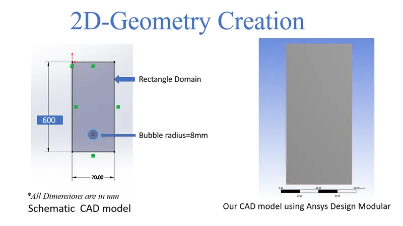
1. Geometry Creation:
The Reactangular domain Geometry was designed using a separate cad package using Solidworks. Then the geometry was imported to Ansys design modular for future control volume creation as it defines the fluid flow domain.
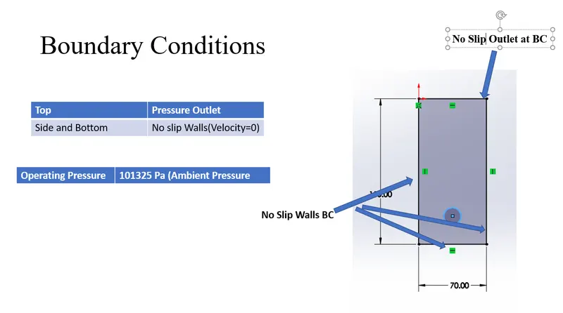
2. Boundary Creation and Meshing
After the control volumes are perfectly created the boundary tags were created in order to assign the different boundary conditions ie. velocity, temperature(if needed), or some other physics. For this geometry, 4 different boundary tags or names were created that were used earlier to assign the boundary condition. The 4 names are Top, Bottom, Left and Right. These Boundary tags were set to no-slip wall condition or friction walls that mean velocity near to wall will be zero.
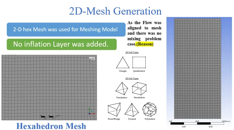
2 Dimensional Quad Mesh was generated to save the computational resources and the flow was aligned to mesh
3. Case Study Setup
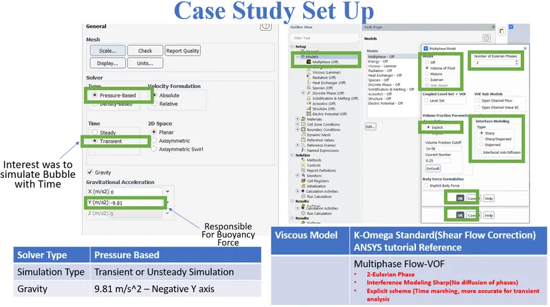
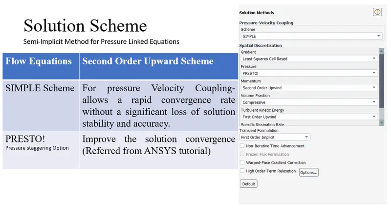
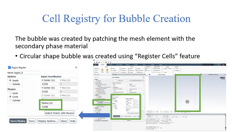
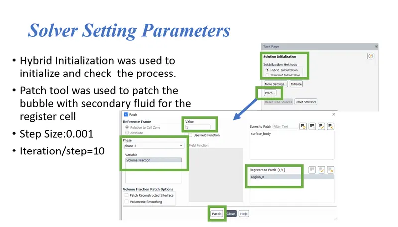
For setting up the case study Ansys Fluent was used in order to simulate the case study.
The various parameter was considered while setup this case study. The case study setup dock was used to set up the problem which appears on the left-hand side of the Ansys
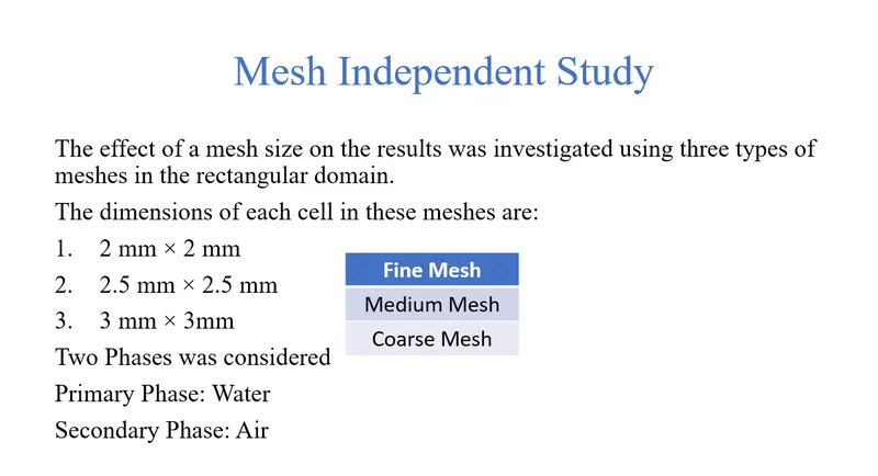
4.Mesh Independent Study
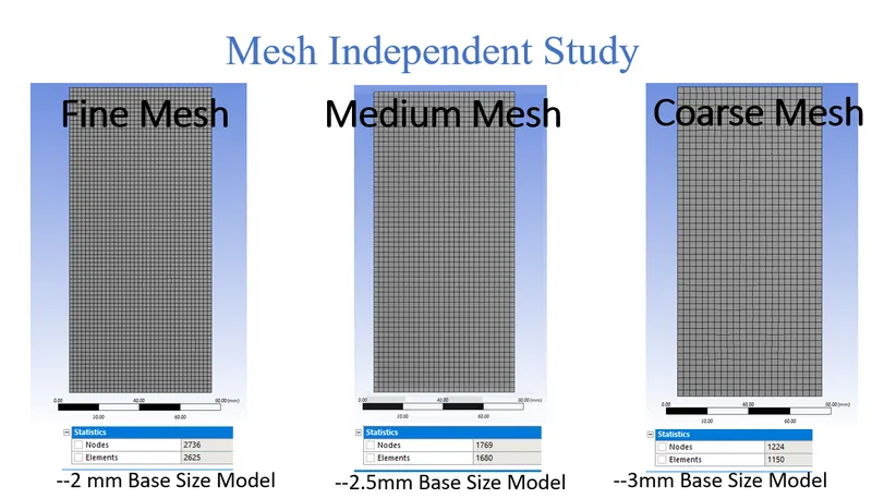
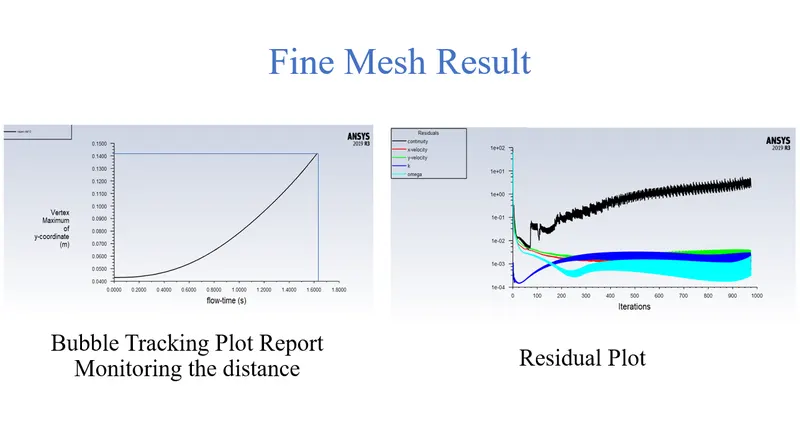
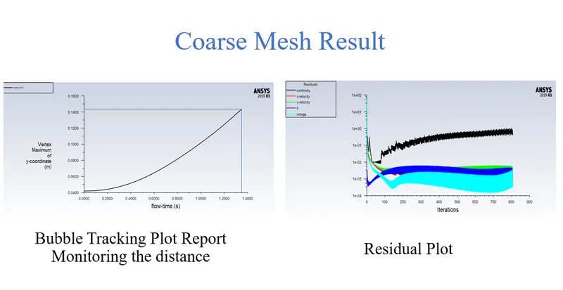
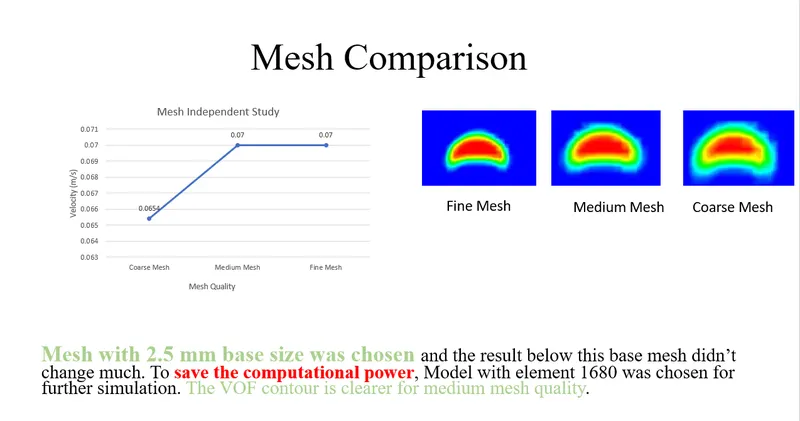
Fine Mesh Result-2 mm Base Mesh
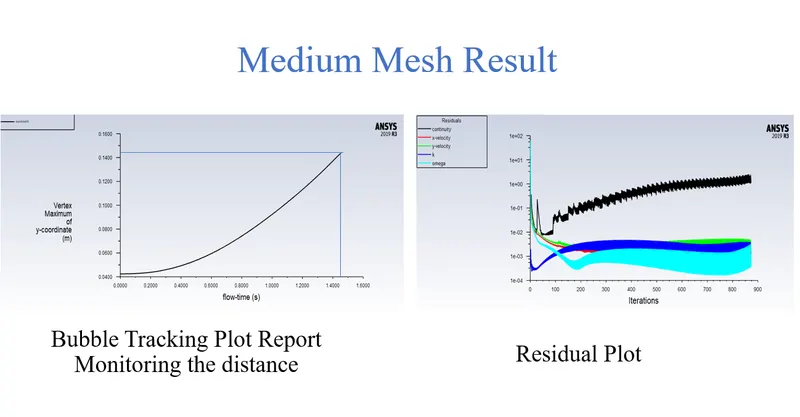
Medium Mesh Result-2.5 mm Base Mesh
Coarse Mesh Result-3mm Base Mesh
Case Study 1. Air bubble rising in Different Fluid medium(Liquid Ammonia, Water, Engine oil and Corn oil)
In this study, 4 different fluids were used to analysed to study the bubble rise velocity.

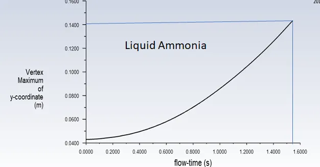
1 Simulation: Liquid Amonia
Maximum Vortex Plot Report
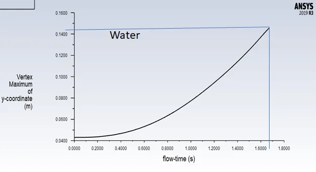
2 Simulation: Water
Maximum Vortex Plot Report
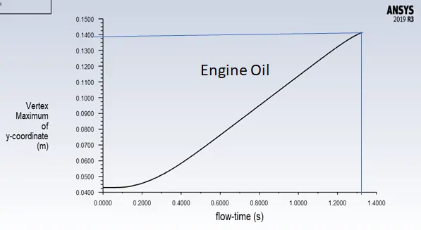
3 Simulation: Engine Oil
Maximum Vortex Plot Report
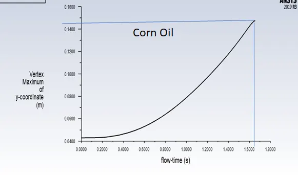
4 Simulation: Corn Oil
Maximum Vortex Plot Report
Case Study 2. Air bubble rising in Water (Different Temperature)
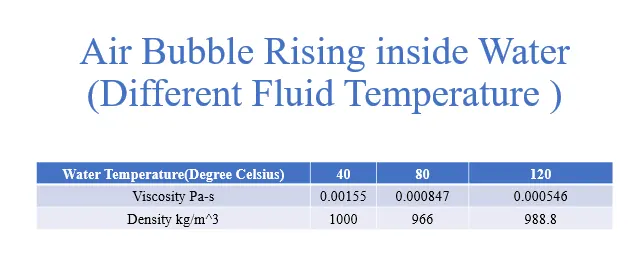
Thermophysical properties were used to define the properties of the fluid water at different temperature
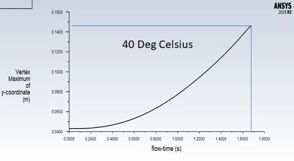
1 Simulation: Water at 40 Deg Celcius
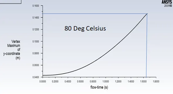
2 Simulation: Water at 80 Deg Celcius
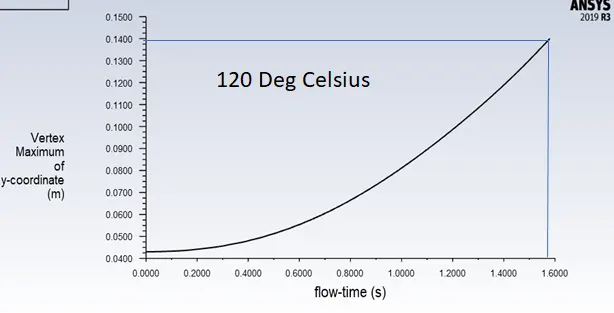
3 Simulation: Water at 120 Deg Celcius
Conclusion
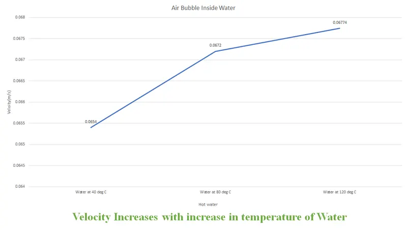
With the increase of temperature, the influence of pressure on liquid viscosity became weakened, resulting in less effect of pressure on the bubble shape and rise velocity.
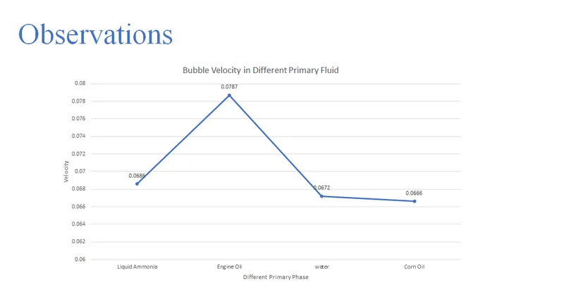
- The purpose of this project was achieved successfully, CFD was utilized in studying the gas bubbles rising under buoyancy effect. Regarding the velocity, It was noticed that when the primary phase was changed the engine oil recorded the highest followed by liquid ammonia, water and finally corn oil.
- Engine Oil > Liquid Ammonia > Water > Corn Oil.
- It was indicated that the velocity increased as the temperature of the fluid increased. The reason behind that is the influence of pressure on liquid viscosity became weakened, resulting in less effect of pressure on the bubble shape and rise velocity.