Reinforcement detailing of Columns from ETABS output
QUESTION:
Reinforcement detailing of columns in Etabs 2018.
The ETABS file for a G+4 building is provided. Run the analysis and design the RCC Moment Resisting Frame. The following challenge deals specifically with two columns at the following grid intersections.
- 3A
- 3B
- Provide details of longitudinal reinforcement for the two columns, from foundation to terrace level. Sketch the column cross sectional & elevation details or draft it using autocad software.
- Show shear reinforcement & lapping details as per special confining reinforcement provision of clause 8.1 of IS 13920 - 2016.
ANS:
AIM:
- To Provide details of longitudinal reinforcement for column 3A & 3B, from foundation to terrace level
- To sketch the cross section and elevation details of the above columns using autocad.
- To display shear reinforcement & lapping details as per clause 8.1 of IS 13920 - 2016.
INTRODUCTION:
- The minimum dimensions of the member shall not be less than 200 mm.
- However, in frames that have beams with the center to center span exceeding 5m or columns of unsupported length exceeding 4m, the shortest dimensions of the column shall not be less than 300 mm.
- This is done to avoid column failure (strong column weak beam concept).
- Lap splices shall be provided only in the central half of the member length.
- It should be proportioned as a tension splice. Hoops shall be provided over the entire splice length at spacing not exceeding 150 mm from the center-to-ceriter not more than 50% of the bars shall be spliced at one section.
- Transverse reinforcement for circular columns shall consist of spiral or circular hoops.
- In rectangle columns, rectangular hoops may be used A rectangular hoop is a closed stirrup having a 135-degree hook with a diameter extension (but not less than 75 mm) at each end that is embedded in the confined core.
Special confining reinforcement shall be provided over a length from each joint face towards the mid span and on either side of any section, where flexural yielding may occur under the effect of earthquake.
when a column terminates into a footing or mat special confining reinforcement shall extend at least 300 mm into the footing or mat.
PROCEDURE:
STEP: 1
1) Open the provided G+4 Etabs file in software
2) Go to ribbon click on analyze < run analysis
STEP: 2
1) go to tool ribbon
2) Click on the Concrete Frame Design tool < Display Design Info option
3) Choose design output as Longitudinal Reinforcement as shown below.
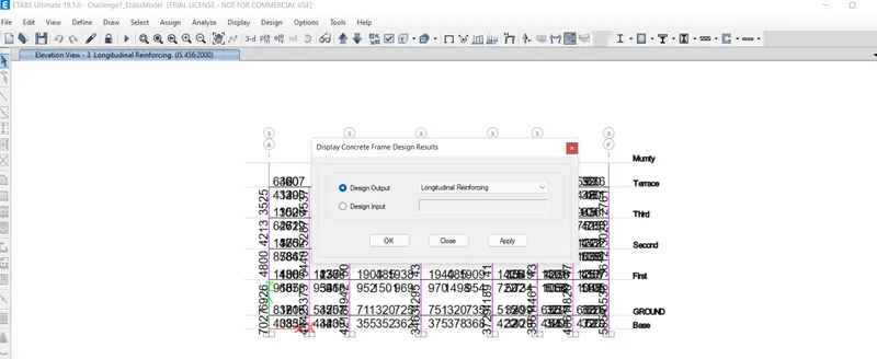
4) After Selecting the Longitudinal Reinforcement click on Elevation View select 3 < apply <ok
5) Go to set veiw option< uncheck beam
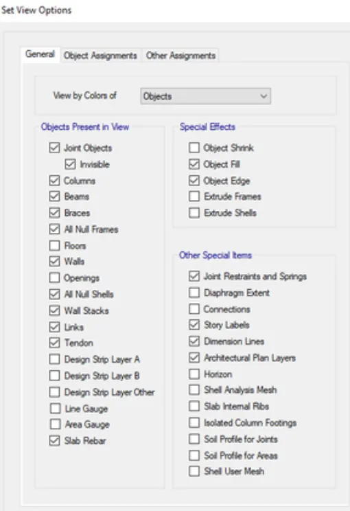
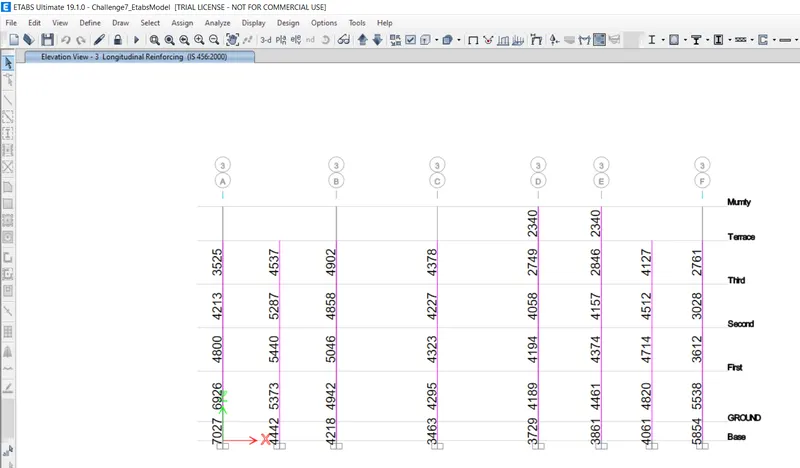
STEP: 3
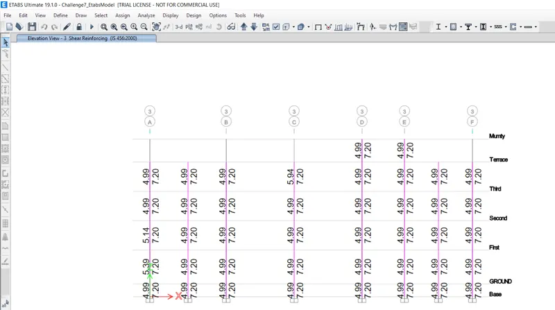
1) For Shear reinforcement, Click the Concrete frame design tool < Display Design Info option
2) Choose Shear Reinforcing.
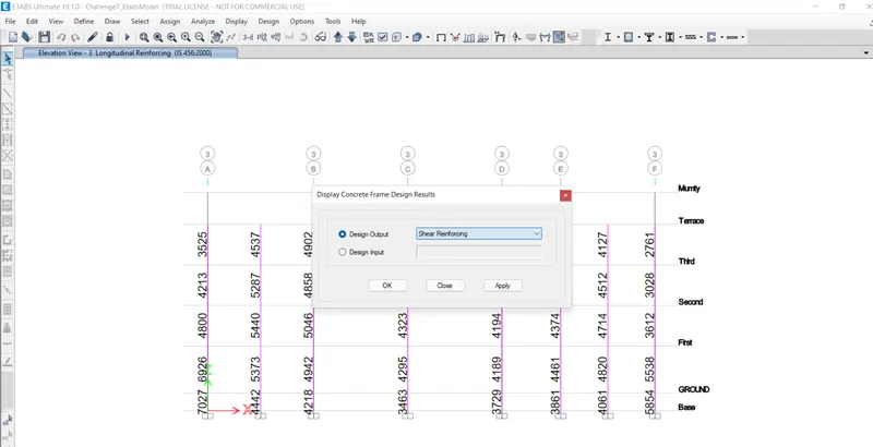
3) Click apply and ok.
After selecting the Shear reinforcement option the shear reinforcement values are obtained at each column.
STEP: 4
Now we need to calculate the reinforcement details for 3A and 3B
so,
STEP: 5
calculate the reinforcement details FOR GRID: 3A
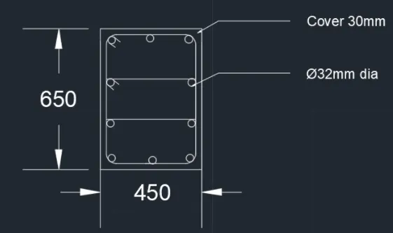
- The Maximum Ast for the column 3A to be considered as per the ETABS design is as follows: -
- The highest of the Longitudinal reinforcement of the column from the Base to Terrace are: 7027,6926,4800,4213,3525 = 7027mm^2 is Provided for the Column.
- The reinforcement detailing for the Column is shown below:
- From the Base to Terrace The Maximum Ast = 7027mm^2
- Total no of longitudinal bars= (Total Asc of column)/(Asc of the any dia bar per meter)
- So, if we select 10 nos of 32mm dia bar
- i.e., 10* 804 = 8040mm^2
- Provide 10 bars of 32mm diameter for the column = 8040mm^2 >7027mm^2
- Hence ok!
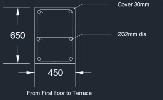
- From the first floor to Terrace The Maximum Ast = 4800mm^2
- Total no of longitudinal bars= (Total Asc of column)/(Asc of the any dia bar per meter)
- So, if we select 6 nos of 32mm dia bar
- i.e., 6* 804 = 4824mm^2
- Provide 6 bars of 32mm diameter for the column = 4824mm^2 >4800mm^2
- Hence ok.
STEP: 6
calculate the reinforcement details FOR GRID: 3A
- The Maximum Asc for the column 3B to be considered as per the ETABS design isas follows: -
- The highest of the Longitudinal reinforcement of the column from the Base to Terrace;
- That is the highest of 4218,4942,5046,4858,4902 is 5046mm^2 is Provided for the Column.
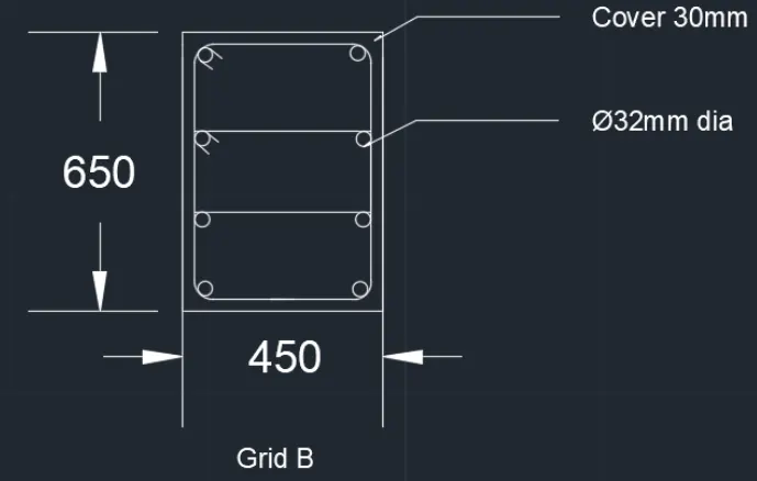
- The reinforcement detailing for the Column is shown below:
- From the Base to Terrace The Maximum Ast = 5046mm^2
- Total no of longitudinal bars - (Total Asc of column)/(Asc of the any dia bar per meter)
- So, if we select 8 nos of 32mm dia bar
- i.e., 8* 804 = 6432mm^2
- Provide 8 bars of 32mm diameter for the column = 6432mm^2 >5046mm^2
Hence ok.
STEP: 7
Special confining reinforcement shall be provided over a length from each joint face towards the mid span and on either side of any section, where flexural yielding may occur under the effect of earthquake.
when a column terminates into a footing or mat special confining reinforcement shall extend at least 300 mm into the footing or mat.
As per clause 8.1
shear reinforcement to be provided as:
i) 1/4th of minimum member dimensions
ii) 6 times of smallest longitudinal rebar
iii) 100 mm
Therefore shear link is = 100 mm
RESULT:
- Provided the details of longitudinal reinforcement for column 3A & 3B, from foundation to terrace level
- Displayed the cross section and elevation details of the columns using autocad.
- Displayed shear reinforcement & lapping details as per clause 8.1 of IS 13920 - 2016.