Reinforcement Detailing of Beams from ETABS output
Ans. I have a design three span continous beam along grid A and a7 span continous beam along grid three
Frist go to analysis and then go to simpaly press the concrete design botton
which will design the longnitudal reinforcement and shear reinforcement for all the fram
from includ beam and column Now we are see the longitudinal reinforcement result in the frist level for all the beam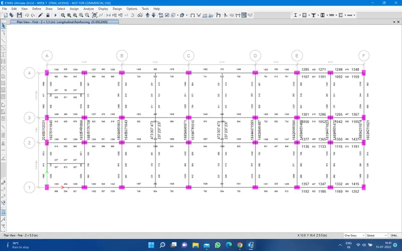
then just go to concrete fram design and select display design info...
Then select the design output and select shear reinforcement and apply and ok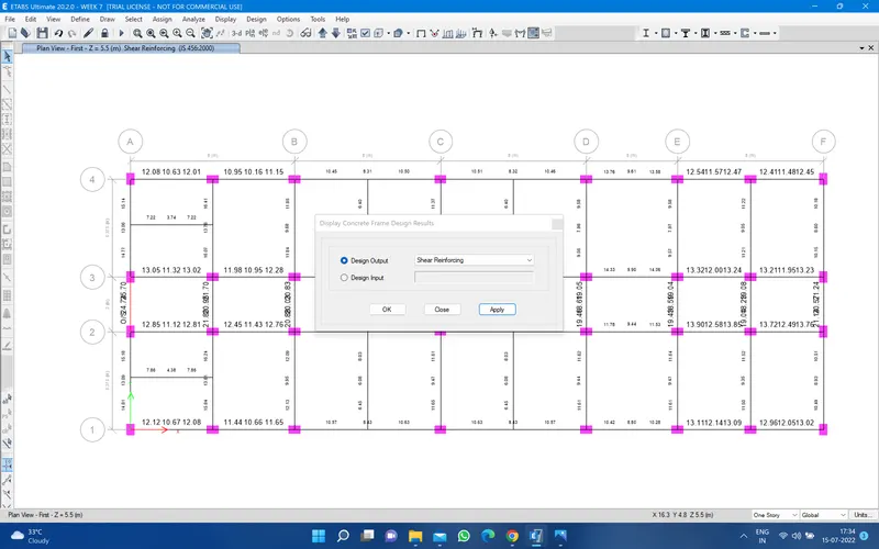
Then go to check the details of particular section
just go to a section and left click and you have open a window and click on the detail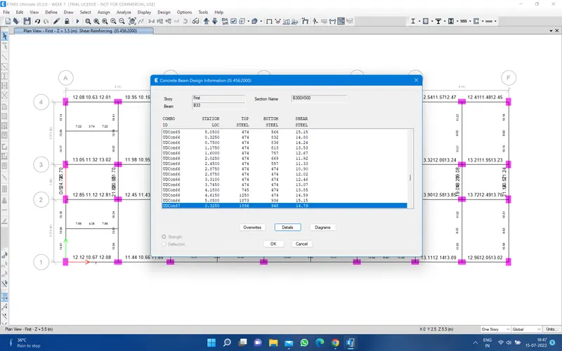
The second task from this chaillenge is to identify why the beam the mid span fail
For that just open the beam along grid A the mid span got fail so we can notic o/s this means over stress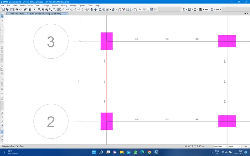
this is has increse beond the aloble velue thats why the reinforcement is imposibal to calculate
just right click on that then click on details and again go to shear details click the report on the bottom you can see 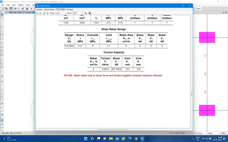
if we use some higher fo0r this beam alone we can increse the capacity for this beam and there for we can make it pass in the shear stress design
*As per IS-13920_2016 clous 6.3.3(b)
sway shear force to right
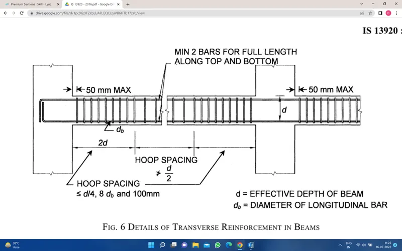
For the lenght of 2d (where d is the effective depth of the beam) we should keep certain shear reinforcement spacing with the `<= d/4, 8d_b and 100mm`condition and through out in the middel the shear reinforcement spacing should not be grater then d/2 the d is again effective depth of the beam
As per IS-13920-2016 clouse 6.3.3(b)
Sway shear force to right
`V_(u,a)=V_(u,a)^(D+L)-1.4(M_u^(As)+M_u^(Bh))/L_(AB)`
`V_(u,b)=V_(u,b)^(D+L)+1.4(M_u^(As)+M_u^(Bh))/L_(AB)`
we have
`M_(as)=174 KNm`
`M_(bh)=293KNm`
`L_(ab=4.725m`
`V_(d+l)=92KN`
after solving the question
`V_(u,a)=46.37KN`
`V_(u,b)=230.37KN`
Sway shear force to left
`V_(u,a)=V_(u,a)^(D+L)-1.4(M_u^(Ah)+M_u^(Bs))/L_(AB)`
`V_(u,b)=V_(u,b)^(D+L)+1.4(M_u^(Ah)+M_u^(Bs))/L_(AB)`
we have
`M_(ah)=234KNm`
`M_(bs)=155KNm`
`L_(ab=4.725m`
`V_(d+l)=70KN`
after solving the question
`V_(u,a)=-45.26KN`
`V_(u,b)=185.23KN`
In reinforcement drawing - for the RC beam along grid A
you can see we have not followed the sample given in the chaillenges at the support does not matter
where spacing is requried for my shair reinforcement desigh as pr ETABS it means provided 100mm spacing at all support
in the second span the span is so shorter I have no other choise to provided 100mm spacing througn out the span and for other span as well I have provided the 100m spacing only at the support and midspan 8m dia 175mm spacing i have use and minimun reinforcement is 3 member of 20 mm dia beam top 3 member 20mm dia beam bottom ad additional reinforcement at support top and support bottom
About the second beam____
7 span continous beam along grid 3 and here also the spacing to behind the support is 100mm spacing for shear I have follow that one and other reinforcement are as per the ETABS design result only the additional reinforcement I have provided support from the main steel to setisfied ETABS result only and extantion of those additional reinforcement I take like L/4 so the span is the 5000 and L/4 1250 extantion from the free support face i have use this is tipical extantion of additional steel that we can use with respect to practice as per IS as well
* If you represent the grids also along the column projection it will be very easy to reffer at the site.
Example
the design reinforcement from the ETABS mite show 199mm^2 or 1271 mm^2 like that but we can not provided the exact amount of steel in the beam due to the commercial product avilable
we have some standard diameter only like 8mm, 10mm, 12mm; 16mm etc.
I have provided the 4 load cases scale Factor for all 1.2 this is my D+L combination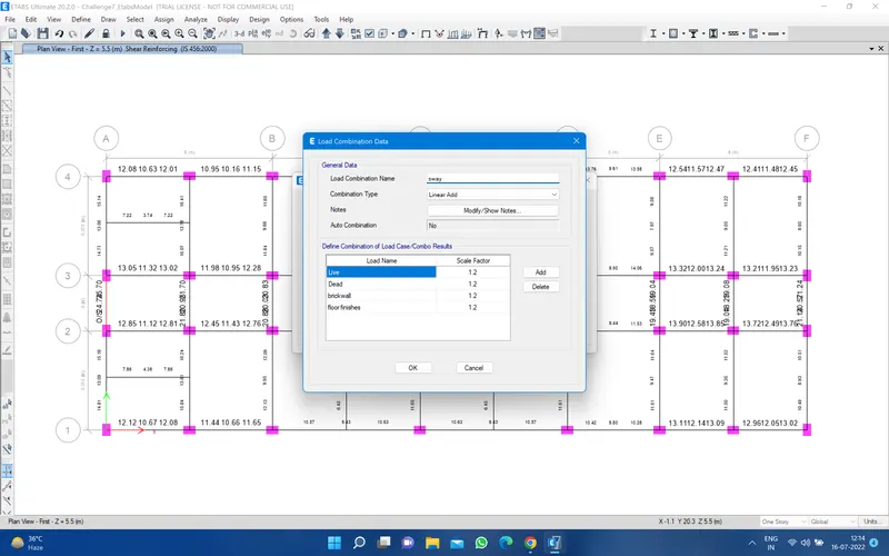
if you want to check the result for sway case shear
just go to member face diagram and select the sway and click on shear 2-2 and apply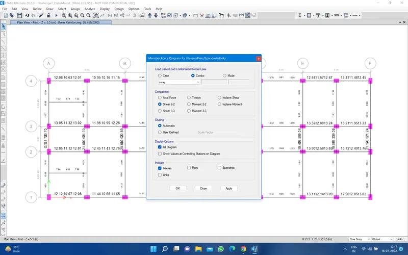
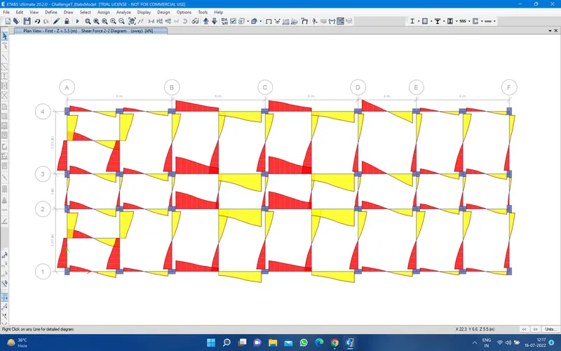
Existing shear capacity in beam as per drawing ;
(As per IS-456-2002 colouse 40.4)
`V_(us)=(0.87fyA_(sv)d)/S_v`
I have
`fy=415N/(mm^2`
`A_sv=151(mm^2)`
d=450mm
`S_v=100mm`
after solving
`V_(as)=245KN`
Hence shear rebar in drawing is okey as per IS-13920 code guidline