Reinforcement Detailing of Beams from ETABS output
OUESTION :
Detail design of beams in Etabs 2018.
The ETABS file for a G+4 building is provided. Run the analysis and design the RCC Moment ResistingFrame. The following challenge deals specifically with two continuous beams in the 1st floor.
1) 3 span continuous beam along grid A
2) 7 span continuous beam along grid 3
Address the following issues thereafter.
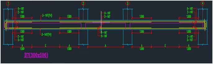
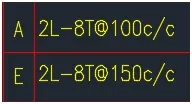
• Provide details of longitudinal and shear reinforcement for the two continuous beams. Sketch the beam elevation details or draft it using autocad software. A sample of how beam elevation details is prepared in consultancy firms is provided below. Participants can prepare it as per their preference:
• Provide reasons for failure of the middle span along grid A. What are the possible ways this issue can be resolved?
• Calculate value of the maximum shear force in any one of the spans in both the continuous beams, as per clause 6.3.3 (b) in IS 13920 – 2016. Also, confirm these values from shear force demand calculated by ETABS.Please note that if longitudinal reinforcement provided is more than required (as per ETABS results), the shear force demand will vary from what is provided by ETABS.
AIM:
- To design the beams in detail using Etabs 2018.
- To Run the analysis and design the RCC Moment Resisting Frame.
- To Provide details of longitudinal and shear reinforcement for the two continuous beams.
- To Provide reasons for failure of the middle span along grid A
- To Calculate value of the maximum shear force in any one of the spans in both the continuous beams
INTRODUCTION:
• Beams are horizontal structural elements used for the supporting lateral loads.
• In conventional reinforced concrete structures, beams usually receive load from the floor slab, but may also be subjected to other loads such as wall loads, finishes, services installation, etc.
• The design and detailing of RC bearns involves the selection of the proper beam size and the quantity of longitudinal and shear reinforcement that will satisfy ultimate and serviceability limit state requirements.
• It is very important that the beam reinforcements are placed and arranged properly on site, to avoid construction error.
PROCEDURE:
Step:-1
- First Go to challenge 7 page open it and after starting the challenge download the attached file.
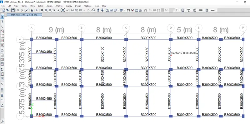
- After downloading the Challenge open it in the ETABS, as shown below.
- Now, to check load combinations,
- click on the concrete frame design tool in ribbon tab
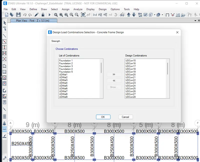
- select design combination
- select the needed combination < click ok
STEP: 2
- After this, we need to check the beam design.
- click on concrete frame design icon
- selet start design/check
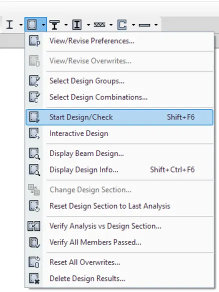
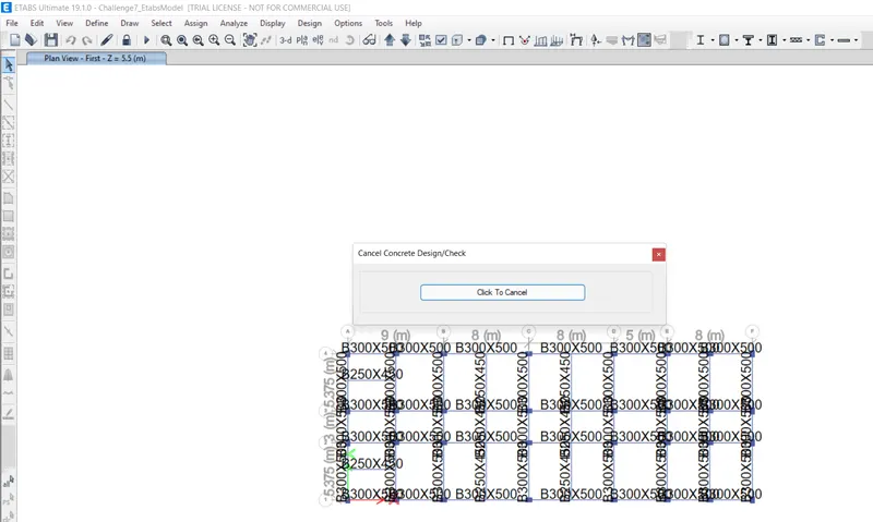
- it starts checking the concrete design
STEP: 3
- after it is done, go to plan view.
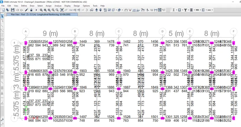
- as we can see above the detaling of column and beam in plan
- Further we need to provide reinforcement details for Grid:A and Grid:3
STEP: 4
-
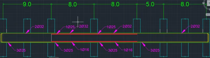
Next we need to draw the Reinforcement diagram of beam along Grid-3, and also need to provide the reinforcement details.
- AT TOP:
- The maximum Ast for the top support is 1904mm
- The maximum Ast for top middle is 453 mm² .
- So, we need to provide 2-dia of 32 mm =1606,
- and additional support of 1 dia of 25mm at middel, as shown in the below figure.
- AT BOTTOM:
- The maximum Ast for the bottom support is 1056mm²
- The maximum Ast for bottom middle is 1501 mm²
- So, we need to provid 3-dia of 25 mm =1470 ,
- and additional support of 1 dia of 16mm = 200.96 at middel, as shown in the below figure.
STEP: 5
-
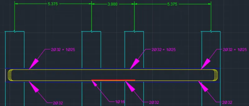
Next we need to draw the Reinforcement diagram of beam along Grid-A, and also need to provide the reinforcement details.
- AT TOP:
- The maximum Ast for the top support is 2045mm
- The maximum Ast for top middle is 477 mm² .
- So, we need to provide 2-dia of 32 mm =1606 ,
- and additional support of 1 dia of 25mm =490 at middel, as shown in the below figure.
- AT BOTTOM:
- The maximum Ast for the bottom support is 1927mm²
- The maximum Ast for bottom middle is 789 mm²
- So, we need to provid 2-dia of 32 mm =1606 ,
- and additional support of 1 dia of 16mm = 200.96 at middel, as shown in the below figure.
STEP: 7
- After providing the beam reinforcement details,
- select the beam< right click<details < shear force
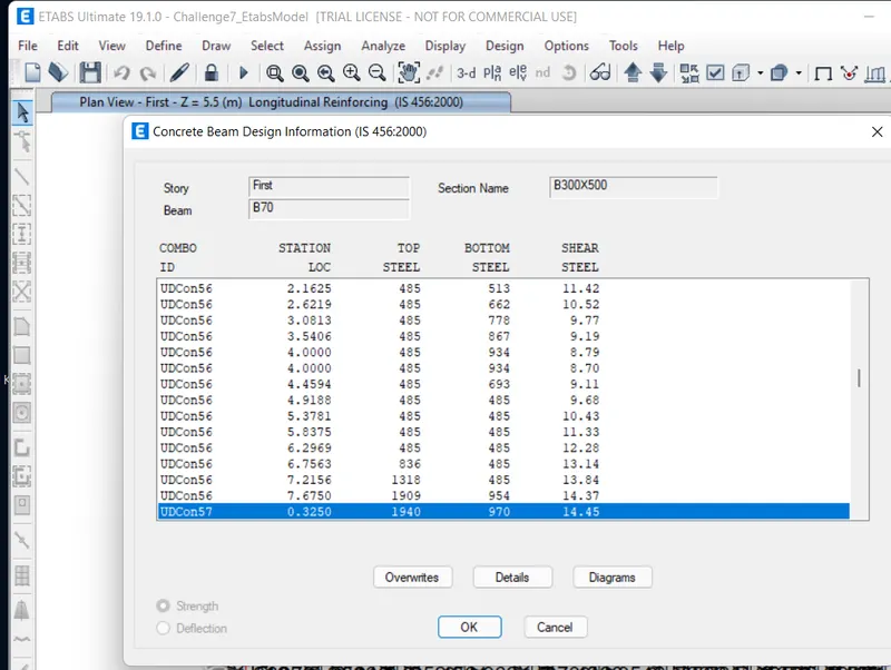
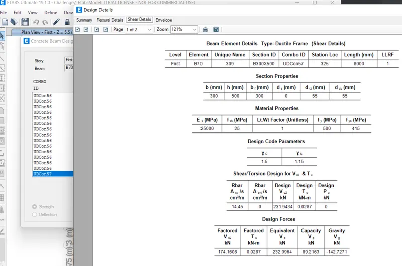
- here, tghe shear details will be displayed as shown in below fig.
- as per clause 6.3.3 the design force is 232.09 KN
- and here we gat Max Shear Force = 174.16 KN
RESULT:
1.
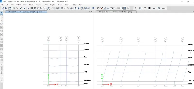
- The analysis of given structure under "concrete frame design" is shown bellow.
2.
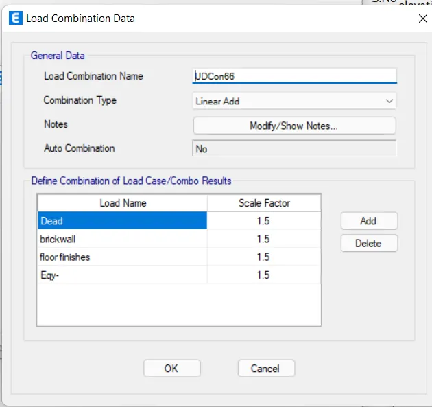
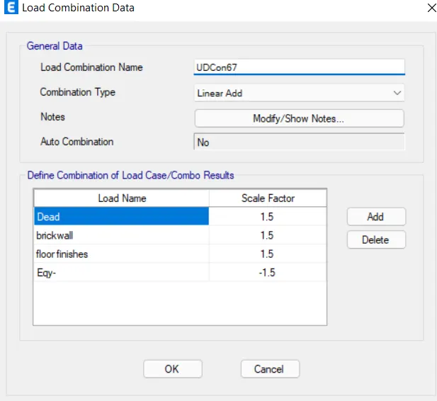
- For 3 span continuous beam along grid A:
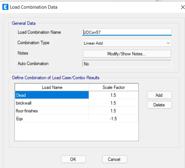
- the load combination are used as shown in fig
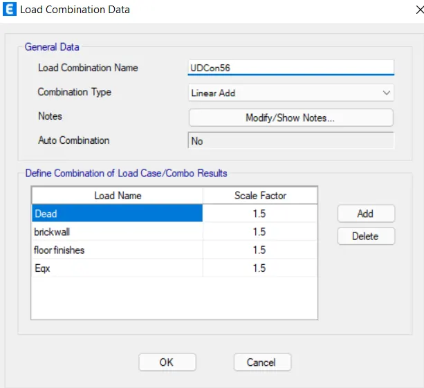
- For 7 span continuous beam along grid 3
- the load combination are used as shown in fig
3.
- The beam are designed succesfully in detail from the ETABS software
- Provided the longitudinal and shear reinforcement for the two continuous beam.
4.
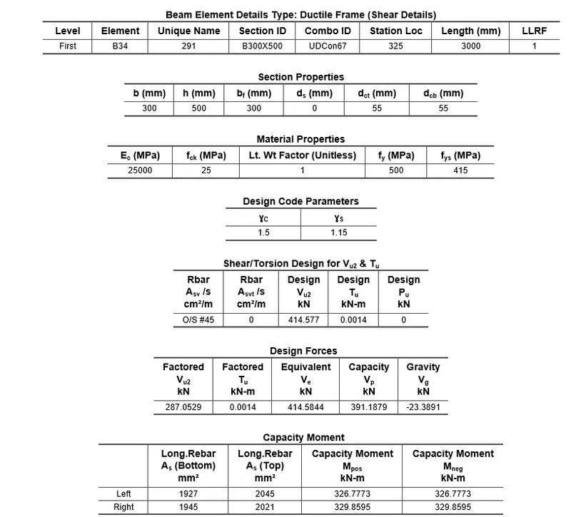
- The reasons for failure of the middle span along grid A is as attached below
- here we can see that due to very high shear force of 414.58KN results in failure of the beam in shear
- To tolerate the high shear reinforcement provide diagonal bars for the beam.
5.
- Also calculated max shear force in continuous beam using ETABS software.