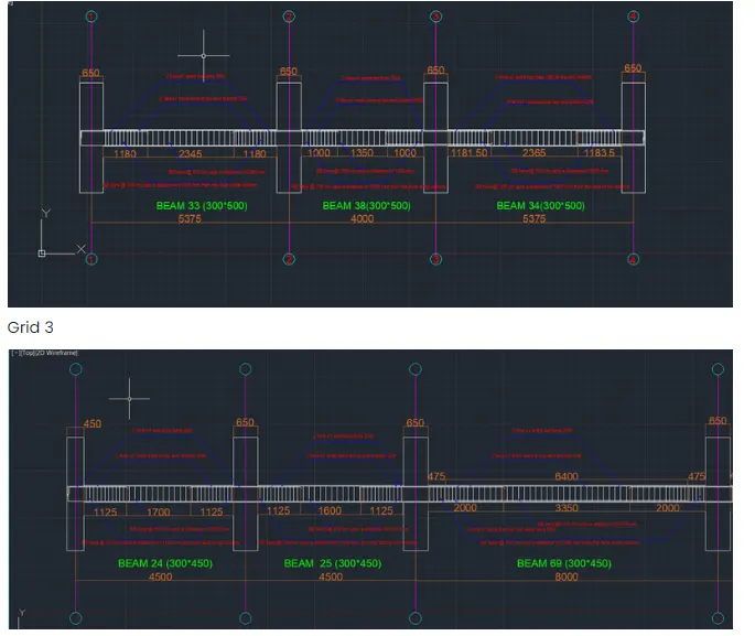
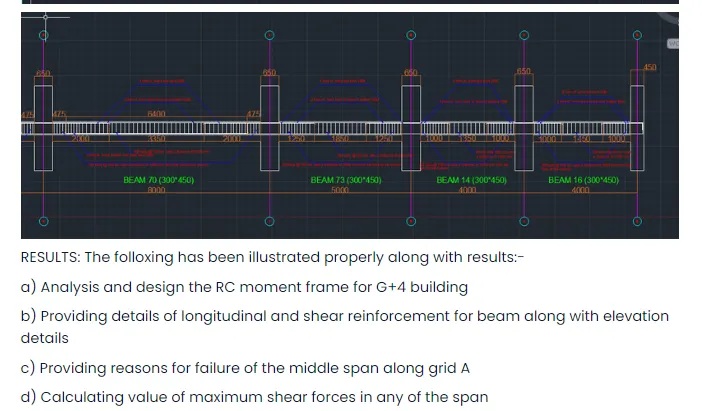
Reinforcement Detailing of Beams from ETABS output
AIM: To do the analysis and create an RCC moment-resistant frame for a G+4 structure.
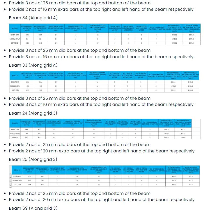
a) A grid-A, 3-span continuous beam
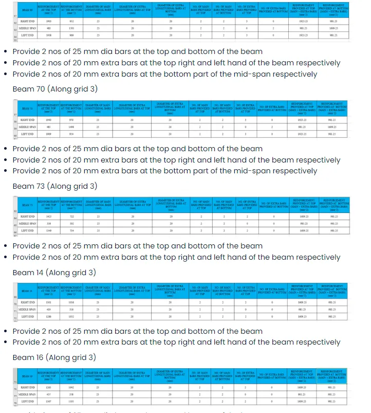
b) A continuous 7-span beam on grid 3.
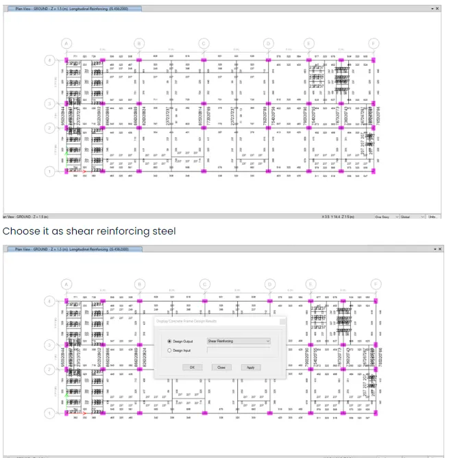
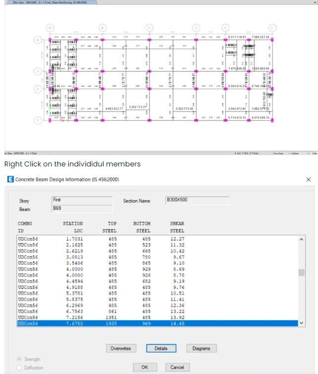
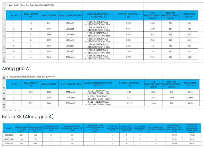
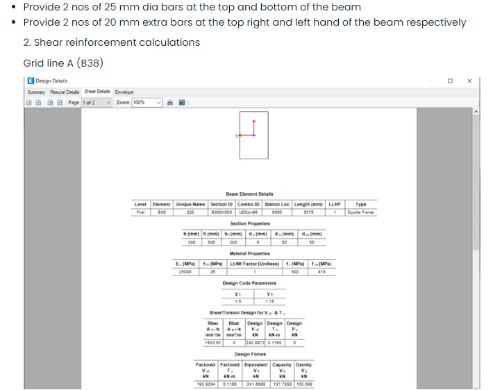
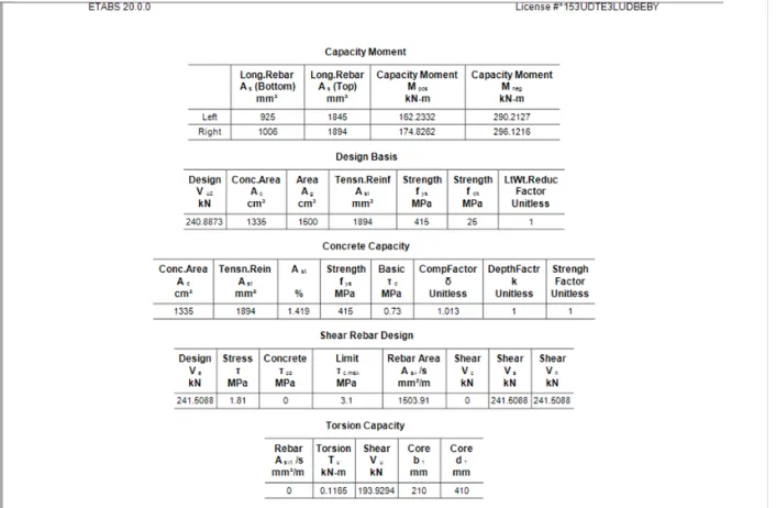
to give information on the shear and longitudinal reinforcement for the two continuous beams. to draught the elevation details by hand or with AutoCAD.
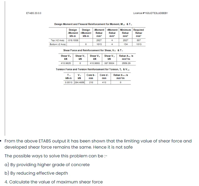
to explain the causes of the middle span along Grid A's failure and potential solutions.
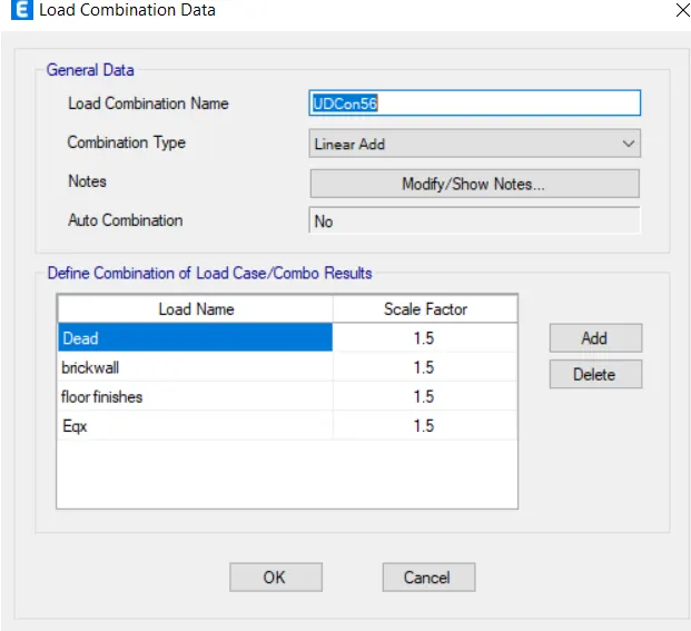
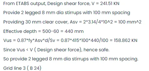
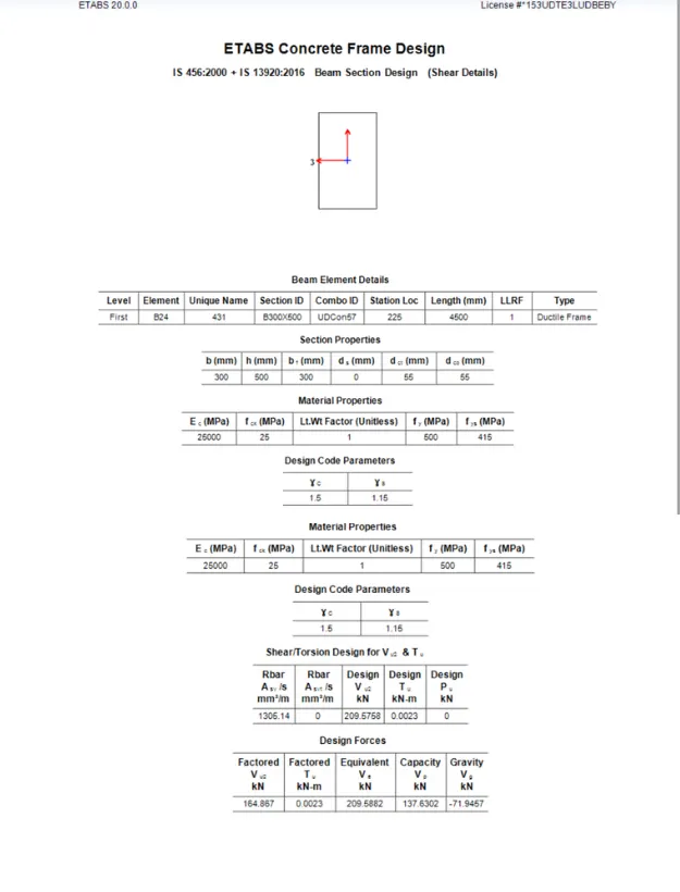
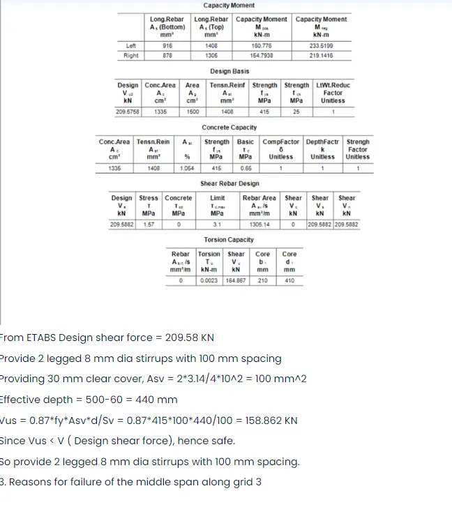
In accordance with IS 13920-2016 clause 6.3.3(b), determine the maximum shear force in any one of the spans in both continuous beams. Additionally, validate these numbers using the ETABS-calculated shear force demand.
Sway to left:-
V(u+a) = 70.58 KN, Mu (As) = 160.776 KN and Mu (Bh) = 233.59 KN
Vu,a = 70.58 - 1.4*(160.774+233.54)/3.9 = -70.998 KN
Vu,a = 70.58 + 1.4*(160.774+233.59)/3.9 = 212.14 KN
Sway to right:-
V(u+a) = 70.58n KN, Mu (Ah) = 154.79 KN, Mu (Bs) = 219.14 KN
Vu,a = 70.58 - 1.4*(154.79+219.14)/3.9 = -54.06 KN
Vu,b = 70.58 + 1.4*(154.79+219.14)/3.9 = 195.22 KN
5. Detailing of beams using AutoCAD
Grid A