Reinforcement Detailing of Beams from ETABS output
Detail design of beams in Etabs 2018.
The ETABS file for a G+4 building is provided. Run the analysis and design the RCC Moment ResistingFrame. The following challenge deals specifically with two continuous beams in the 1st floor.
1) 3 span continuous beam along grid A
2) 7 span continuous beam along grid 3
Address the following issues thereafter.
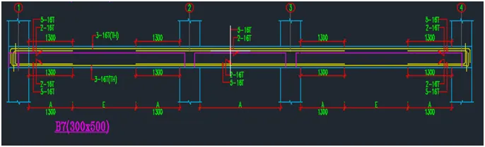
• Provide details of longitudinal and shear reinforcement for the two continuous beams. Sketch the beam elevation details or draft it using autocad software. A sample of how beam elevation details is prepared in consultancy firms is provided below. Participants can prepare it as per their preference:
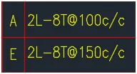
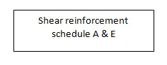
Provide reasons for failure of the middle span along grid A. What are the possible ways this issue can be resolved?
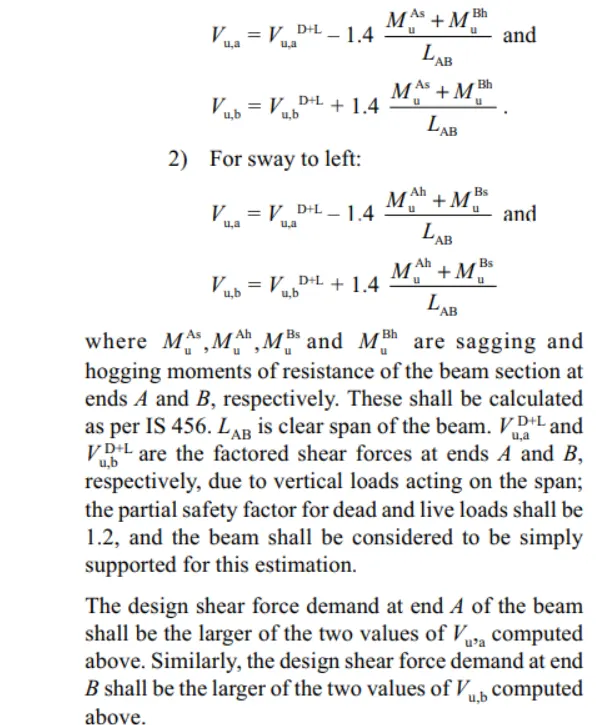
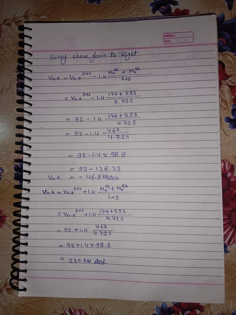
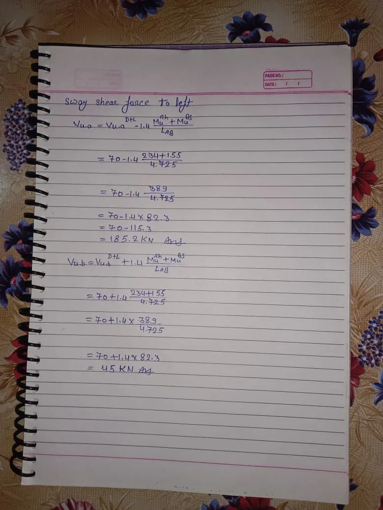
Calculate value of the maximum shear force in any one of the spans in both the continuous beams, as per clause 6.3.3 (b) in IS 13920 – 2016. Also, confirm these values from shear force demand calculated by ETABS.Please note that if longitudinal reinforcement provided is more than required (as per ETABS results), the shear force demand will vary from what is provided by ETABS.
Introduction :
The design and construction of reinforced concrete buildings shall be governed by the provision of
IS 456:2000
steel reinforcement of grade Fe 415 or less can be used
strong steel is not preferable to low strength steel in earthquake-prone regions because the typical stress-strain curve of low steel shows the following advantages a) long yield b) greater breaking strain c ) less strength gain after the first yield.
Longitudinal Reinforcement :
the top as well as the bottom reinforcement shall consist of at least two bars throughout the member length
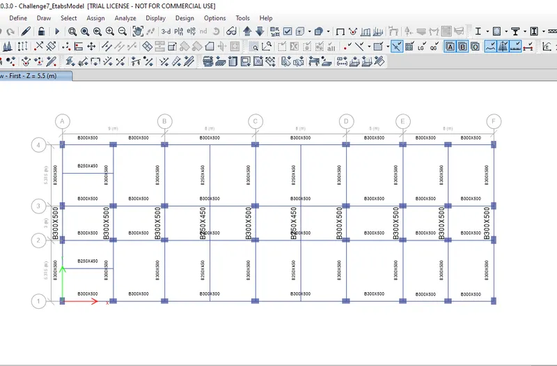
Analysis needs to be done
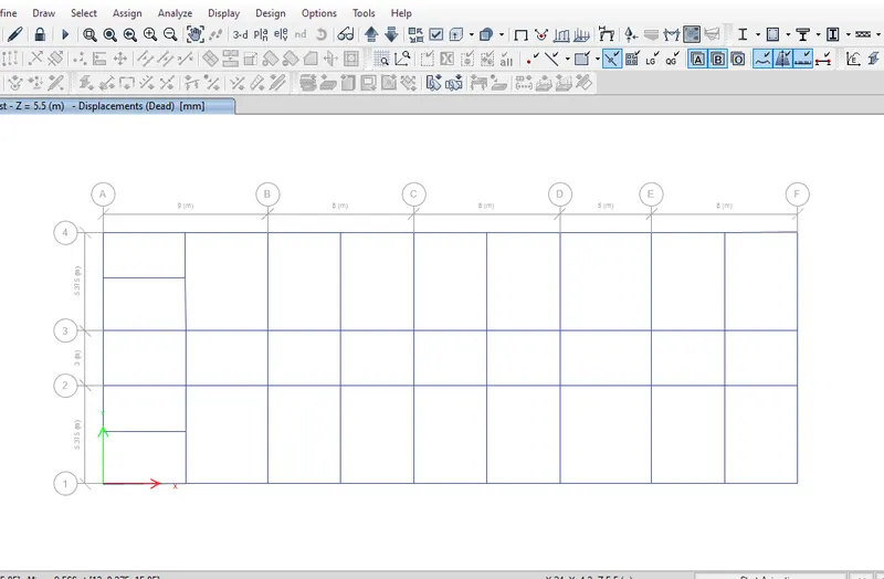
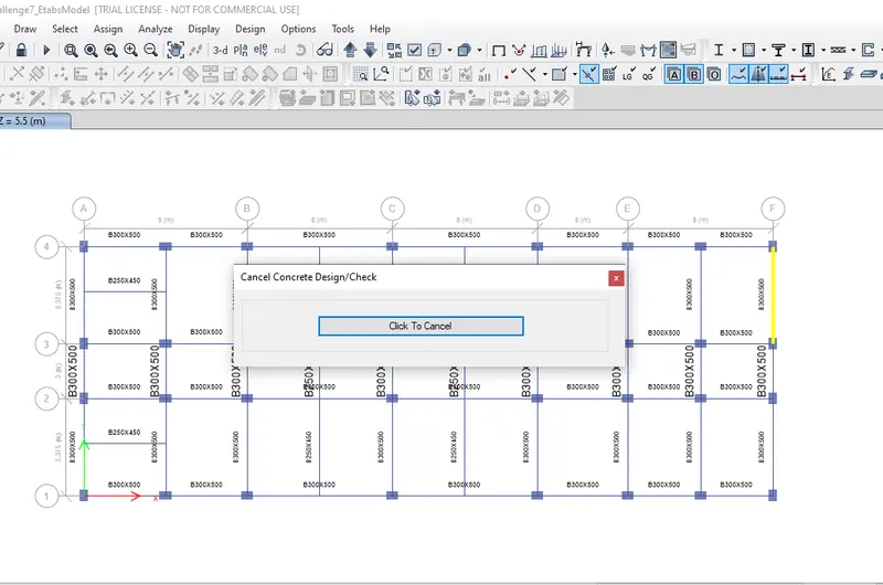
Concrete design is done for this model
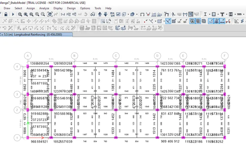
3 span continuous beam along grid A
At the top:
Maximum at end support 2046 mm^2
Minimum at end support 938 mm ^2
Ast for 32 diameter = 804 .24
Ast for 25 diameter = 490
Ast for 20 diameter= 314
Ast for 16 diameter = 201
Ast for 12 diameter = 113
Maximum at the mid supports is 511 mm^2
2 bars of diameter 32mm and 1 bars of 25 mm satisfies the overall Ast
2 x T32 = 1608 mm ^2
T25 = 490 mm^2
2 X T32 + T25 = 2098 mm ^2
or
3 bar of diameter 32 mm satidfies the overall Ast
3 T32 = 2412 mm ^2
At the bottom :
Maximum at the end support is 1945 mm ^2
Maximum at the mid support is 789 mm ^2
2 bars of diameter 32 mm and 1 bar of 25 mm satisfies the overall Ast
2 x T32 = 1608 mm ^2
T25 = 490 mm^2
2 X T32 + T25 = 2098 mm ^2
or
2 bars of diameter 32 mm and 1 bar of 20 mm satisfies the overall Ast
2 x T32 = 1608 mm ^2
T20 = 314 mm^2
2 X T32 + T20 = 1922 mm ^2
7 span continuous beam along grid 3
At the top :
Maximum at end supports is 1940 mm ^2
Maximum at Mid supports is 485 mm ^2
2 bars of diameter 32 mm and 1 bar of 25 mm satisfies the overall Ast
2 x T32 = 1608 mm ^2
T25 = 490 mm^2
2 X T32 + T25 = 2098 mm ^2
At the bottom :
Maximum at end supports is 1105 mm^2
Maximum at mid supports is 1501 mm^2
2 bars of diameter 32mm satisfies the overall Ast
2 X T32 = 1608 mm ^2
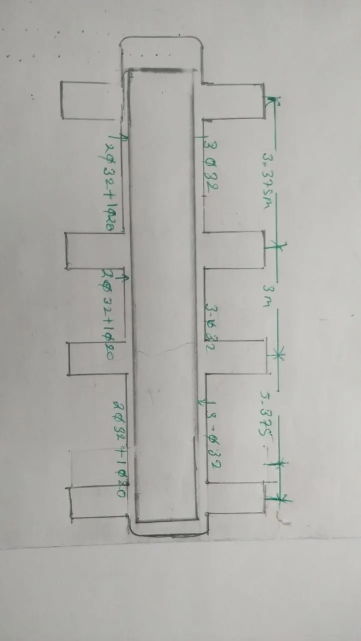
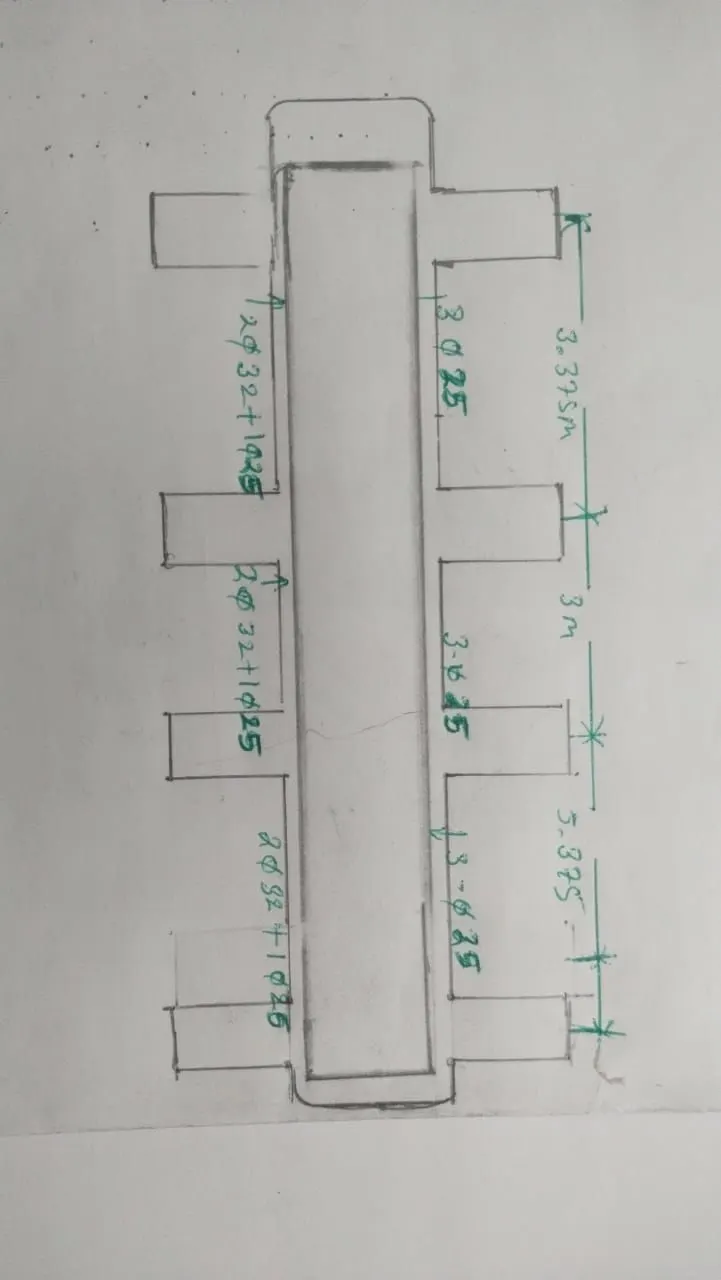
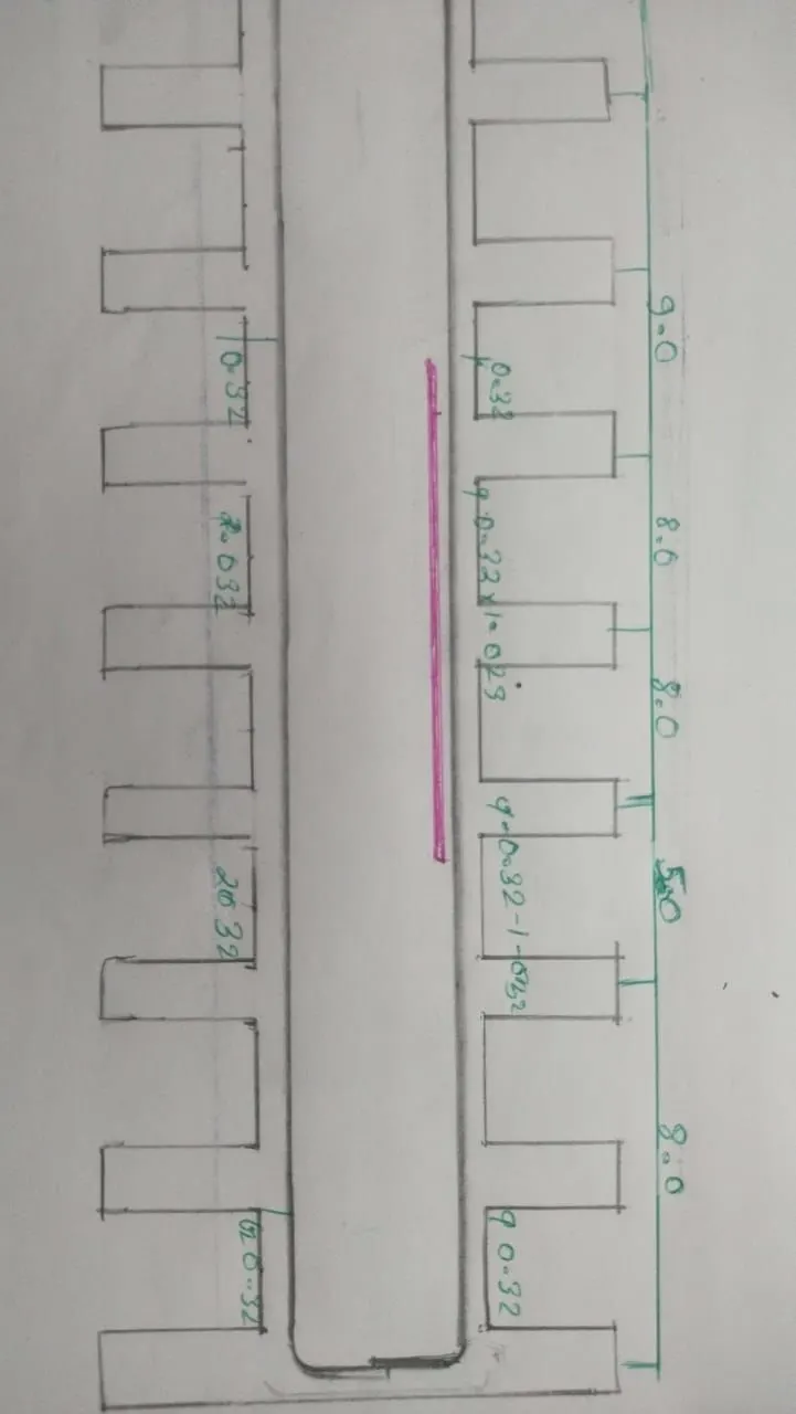
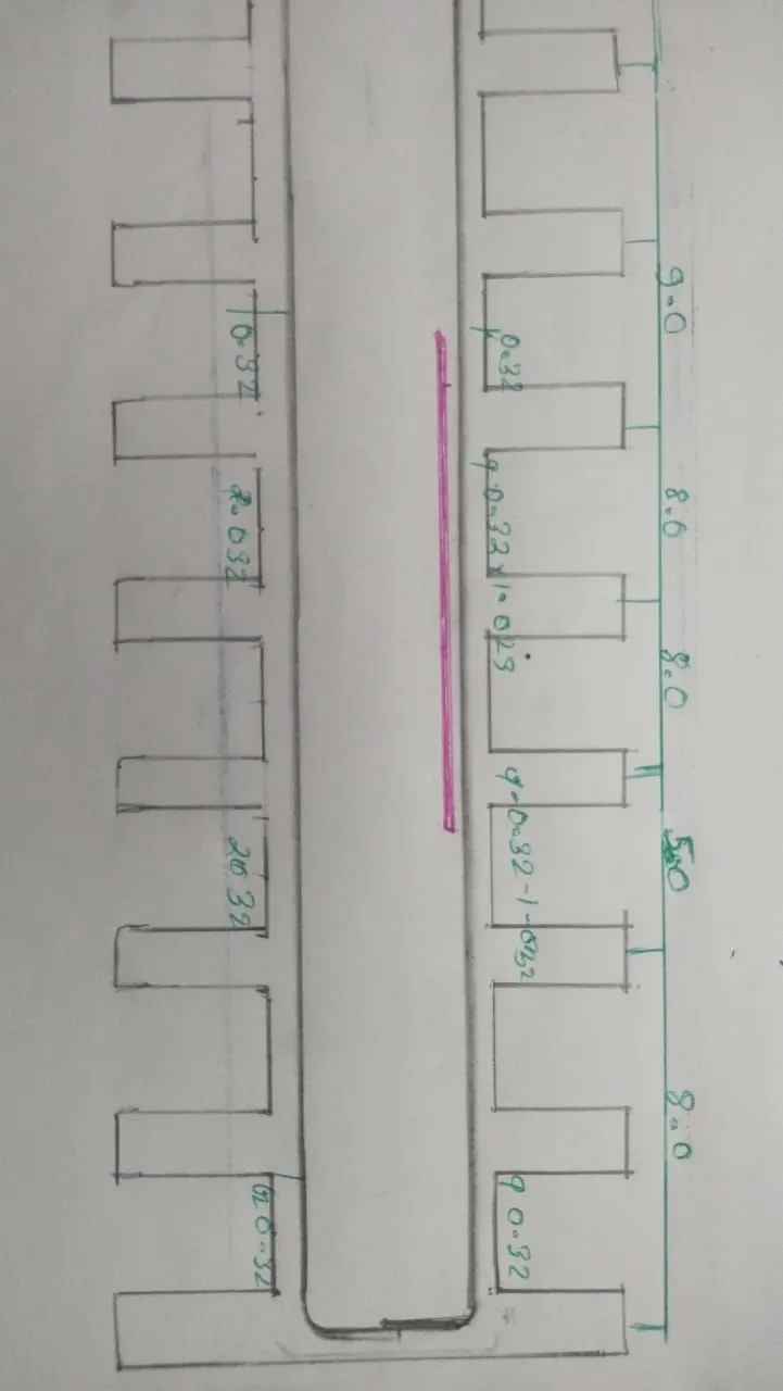
shear reinforce design
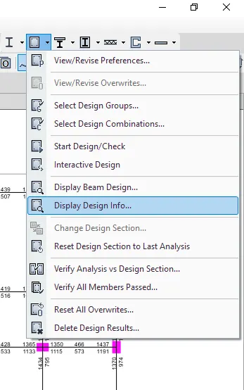
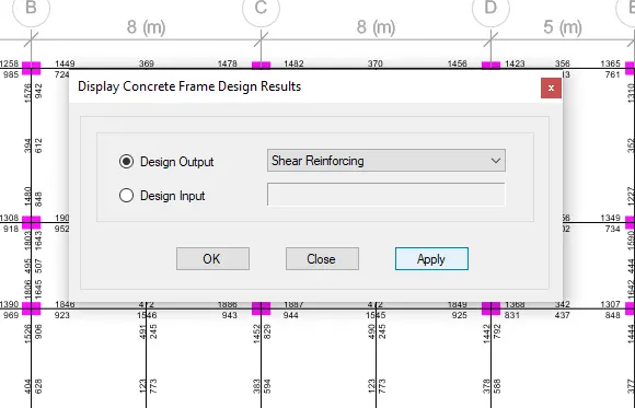
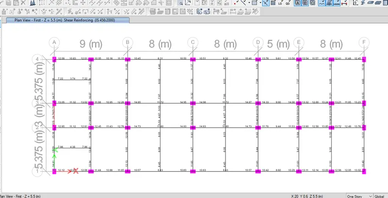
Shear details :
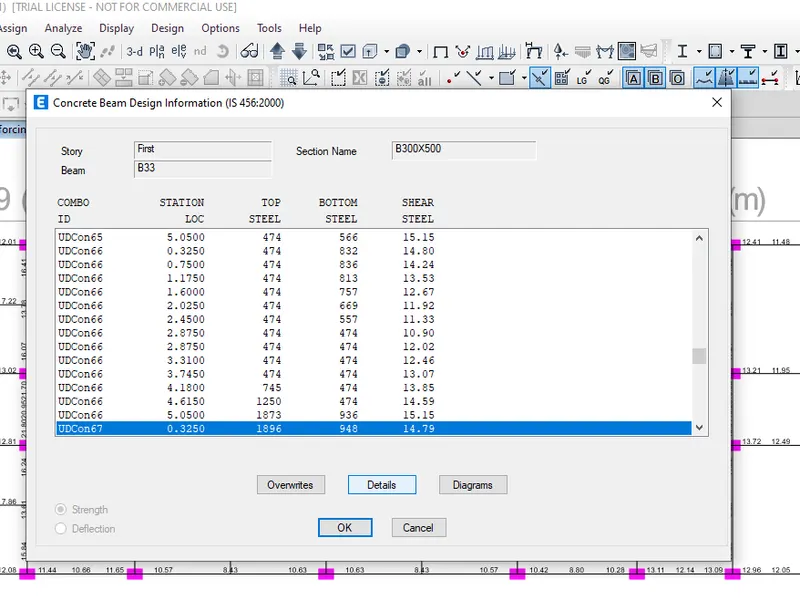
Shear details
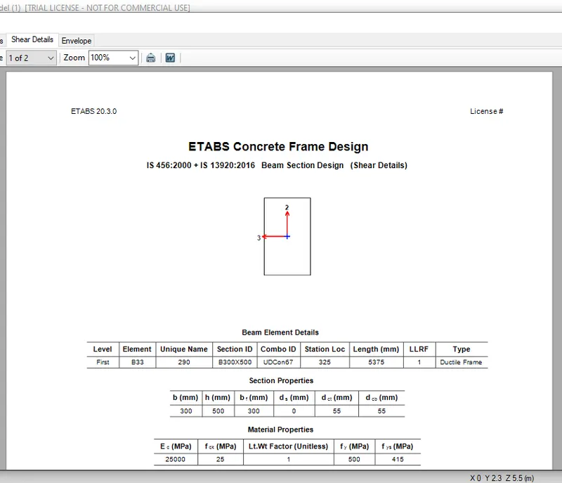
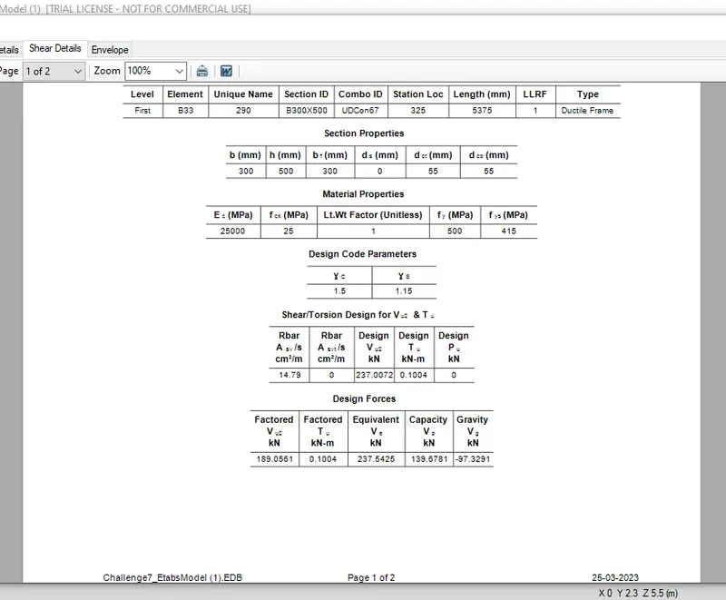
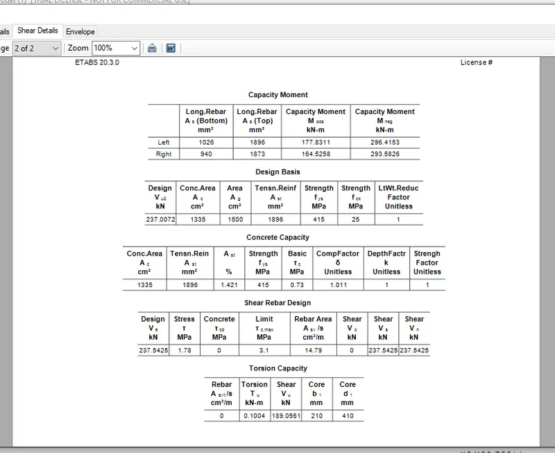
Longitudinal reinforcement of beam at grid-3 from ETABS (mm2)
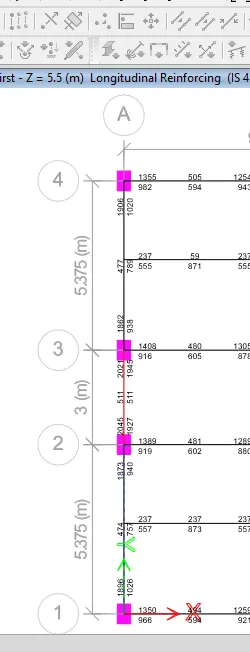
Longitudinal reinforcement of beam at grid-3 from ETABS (mm2)

Shear reinforcement of beam at grid-3 from ETABS (cm2/1000 mm)
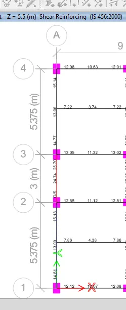
Shear reinforcement of beam at grid-3 from ETABS (cm2/1000 mm)

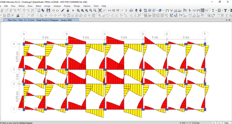
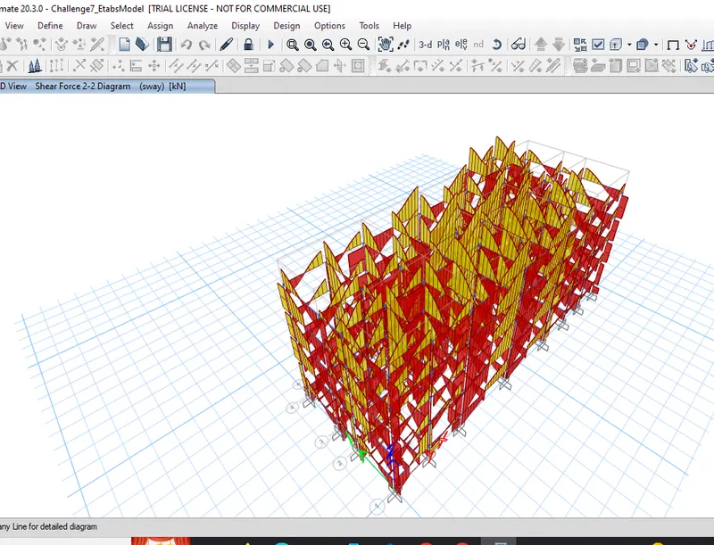
sway: