Reinforcement Detailing of Beams from ETABS output
ETABS file of a G+3 story building is provided.
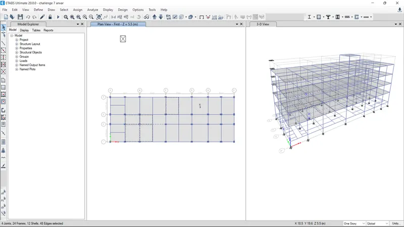
Analysis and design results of two continuous beams in the first floor in purticular are taken into account
a) 3 span continuous beam along Grid A (Beam size = 300 mm x 500 mm)
b) 7 span continuous beam along grid 3 (Beam size = 300 mm x 500 mm)
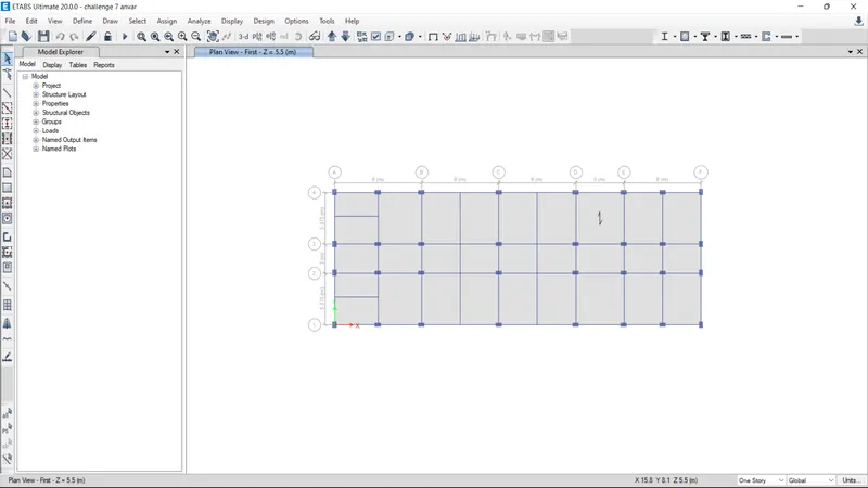
Analysis completed
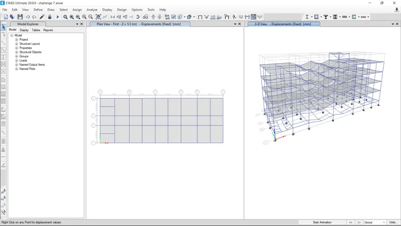
Longitudinal bar design is completed
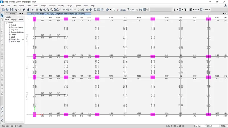
Shear desin is also completed
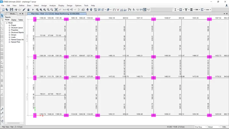
For any RCC member we have to provide minimum reinforcement for the respective members irrespective of the design values due to the following reasons
a) Minimum reinforcements for shrinkage and temperature
b) Reinforcement required for limiting crack width
c) Ultimate limit state design rebar
d) Minimum reinforcement for ductility requirements
Among the above four values greatest value should be taken for reinforcement detailing
Minimum longitudinal reinforcement to be provided as per is 13920-2016 Cl.6.2.1 is given as
Min steel required = Steel ratio x area of concrete
steel ratio = 0.24 sqrt (fck) / fy = 0.24x 5/500 (fck = 25 MPa , Fy = 500 MPa)
area of concrete = 300 x 500 = 150000 mm2
Min steel = 360 mm^2
Minimum shear reinforcement required as per IS 456-2000 Cl 26.5.1.6 is given as
Asv = 0.4 x b x sv /(0.87 Fy)
0.4 x 1000 x 300/ (0.87 x 415) = 332 mm^2
Development Lenghth as per Cl 26.2.1 IS 456-2000 = 41 x dia of main largest bar 6
All members had passed in the design check.
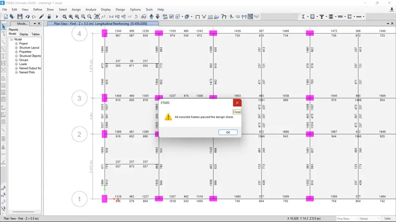
Detailing longitudinal and shear reinforcement of of beam sections
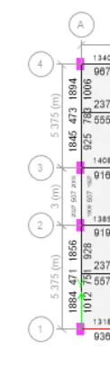
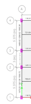
Beam along grid A
Longitudinal steel area in mm2
shear steel area in mm2/m
Beam along Grid 3
longitudinal steel mm2

shear steel in mm2/m

Some important rules to followed as per is 13920-2016 for beam detailing
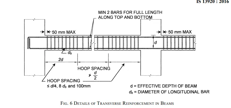
At the span of Two times the effective depth of column we have to provide stirrups at a spacing of lesser of - d/4, 8 times dia of smallest longitudinal bar, 100 mm and in the remining middle span spacing should not be greater than effective depth of column/2
Check for Sway shear rquirement of the beams as per Is 13920-2016 Cl.6.3.3 b
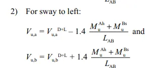
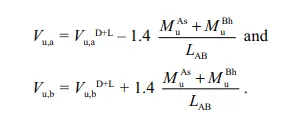
Where Mas, Mah,Mbs,Mbh are sagging and hofgging moments of resistsnce of beam section at ends A and B respectively. Vd+l is the gravity shear force witout any influence of the earthquake loads. Submitted the dead load combination with factor 1.2 as user defined load combination.
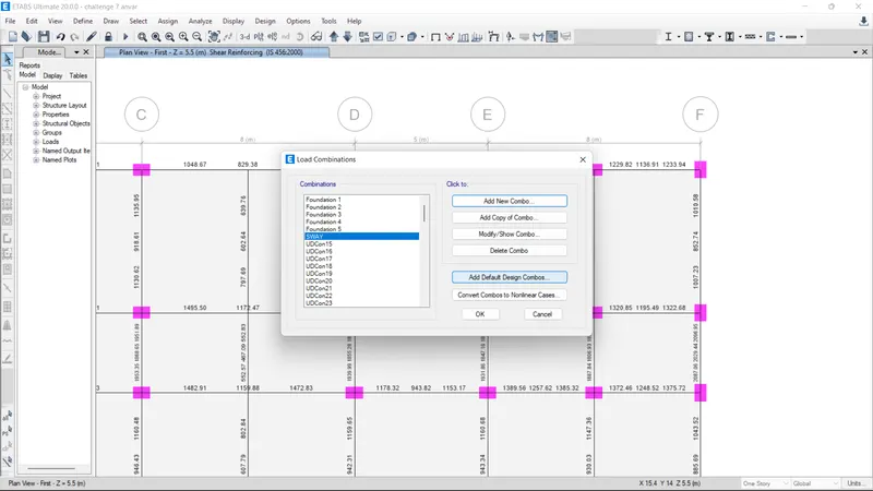
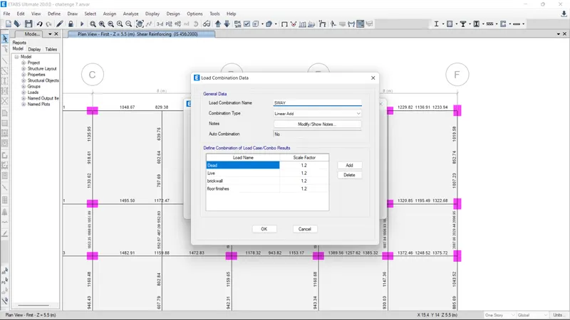
Sway shear check as per Is 13920-2016 Cl.6.3.3 b. considered the beam in Grid 3-B (4.5m span)
From ETABS Results
Vua (D+l) = 53.06 kN
Vub (D+L) = 57.79 kN
Muas = 3.36 kN
Muah = 11.99 kN
Mubh = 15.52 kN
Mubs = 4.52 kN
Lab = 4.5m
From these values applying in equations from Is 13920-2016 Cl.6.3.3 b.
Sway shear force to right
Vua =47.18 kN
Vub = 63.46 kN
Sway shear force to left
Vua = 47.92 kN
Vub = 62.89 kN
The shear reinforcement should sufficient enough to carry the maximum of the above values which is 63.46 kN
REINFORCEMENT DETAILING
Beam along Grid A
Sample calculation of longitudinal rebars in beam b/w Grid 1 and 2
Ast= 1884 mm2 (Top of support 1)
use 25 mm dia bars
Area of one bar = 491 mm2, so use 4 Nos ; 2 at top and 2 at bottom (extra bars for hogging momemt at support)(at top of support 1)
Bottom two bars at top of beam should provide at a distance of 1350 mm (L/4 of span) to resist the hogging momemt at support.
Similarly ast is converted to number of bars of specific diameter to satisfy the momemt requirements.
Sample calculation of Shear rebars in beam b/w Grid 1 and 2
Asv = 1473.6 mm2/m
ude 8 mm 3 legged stirrups; area = 0.786*8*8*3 = 150.9 mm2
As/S = 1473.6;
S= 150.9/1473.6 = 10.2 cm , Provide 8 mm 3 legged stirruos at 10 cm c/c
Asv required at support b/w Grid 2 and 3 is around 2560 mm2 which is higher value.
provide 12 mm 3 legged stirrups ; As=0.786*12*12*3 = 339 mm2
As/S = 2560mm2
S= 339/2560 = 13.2 cm ; Provide 12 mm 3 legged stirrups at 12 mm c/c.
Detailing of reinforcement along Grid A and Grid 3 is done using Autocad and attached as PDF