Reinforcement Detailing of Beams from ETABS output
AIM:
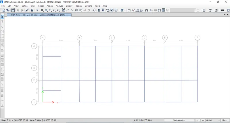
In the given ETABS project we have to analyse and redesign the RCC moment resisting frame in two girds (horizontal and vertical). Find the cause of failure and resolved the issue.
INTRODUCTION:
In the modal we provide the details of longitudinal, shear reinforcement for the two continuous beams and reason of failure of the middle span along grid A. to calculate the value of maximum shear force in any one of the spans in both the continuous beams
PROCEDURE:
STEP 1) Open the Given Model
- Download the model then open
- Model will open in etabs software
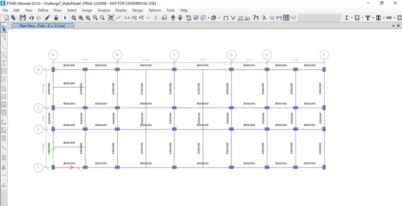
- Check the model and run
- We get the max. & min value of deflection
STEP 2) Reinforcement Detail
- Click on concrete frame design icon
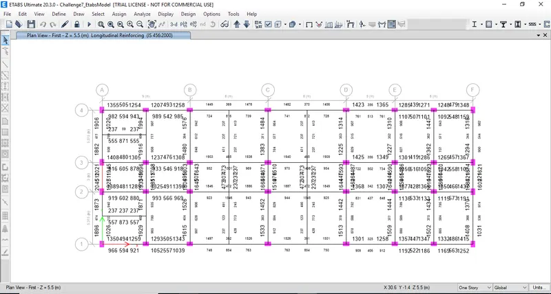
- It will design for longitudinal and shear reinforcement for all the frame
- Drop down the icon concrete frame design and click on display design info
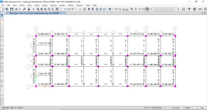
- Select shear reinforcement in display concrete frame design
STEP 3) Identify the mid span beam failure
- We can notice the mid span beam along grid A (between grid 3 & 2) got failed due to over stressed
- The stress is having to increase beyond the allowable value that’s why the reinforcement is impossible to calculate the value
- When we check the shear steel information, 3 combinations are not calculated
- Go to shear steel detail of the mid span beam and check the report at bottom
Resolve the beam failure
- We have to increase the reinforcement
- We have to increase the shear capacity of the concrete i.e., higher grade of concrete
STEP 4) Reinforcement Design
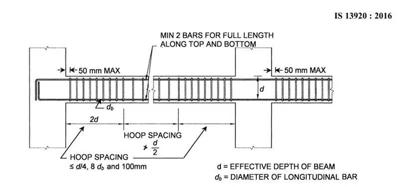
Additional reinforcement guideline from IS 13920-2016 (clause 6)
- In figure for the length 2d where ‘d’ is the effective depth of the beam, we should keep a certain reinforcement spacing with these criteria (`le`d/4,8db and 100 mm)
- Through out in the middle the shear reinforcement spacing should not be greater than d/2
- Need minimum two bar for full length along top and bottom for the seismic design
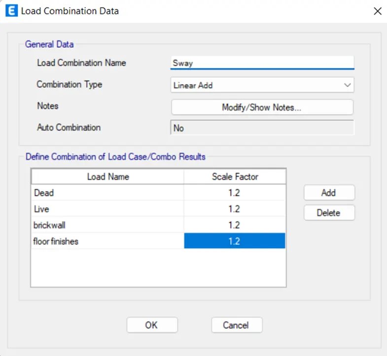
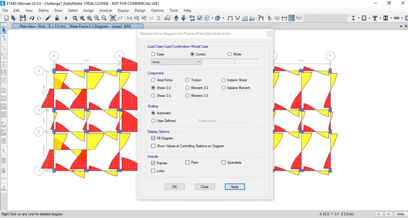
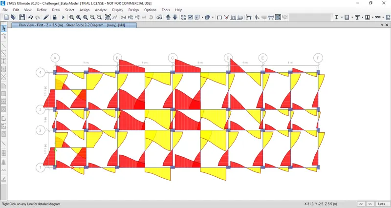
Additional check to verify whether the provided reinforcement in the beam satisfies the sway shear requirement
- During seismic activities consider the portal frame a beam supported by two columns are either side. It will sway to the right and after some time it will sway to the left so in this, we have two cases so for the two cases we should check the sway shear demand in the beam joint for which our reinforcement should satisfy
1. Sway shear force to right
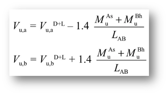
Mas =174kNm
Mbh=293kNm
Lab=4.725m
Vd+l= 92kN
Vu,a=46kN
Vu,b=230kN
2. Sway shear force to left
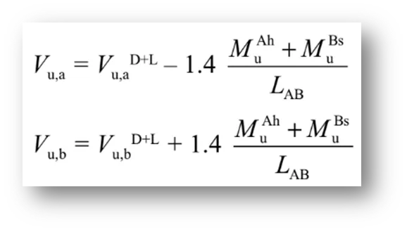
Mbs =155kNm
Mah=234kNm
Lab=4.725m
Vd+l= 70kN
Vu,a=185kN
Vu,b=45kN
RESULT:
Existing shear capacity in beam as per drawing (as per IS 456-2000 clause 40.4)
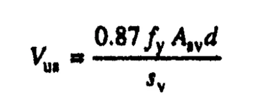
Fy=415 N/mm2
Asv=151mm2
d=450mm
Sv=100mm
Vus=245 kN
Hence shear rebar in drawing is okay as per IS-13920 code guideline