Radar Mast & Final Assembly of Yacht
MODELLING, ASSEMBLY AND RENDERING OF SUNSEEKER PREDATOR YACHT IN SOLIDWORKS
OBJECTIVE: The objective of the project is to model the individual parts of the yacht and then assemble it using Solidworks. The final assembly will then be rendered using Solidworks Visualize.
INTRODUCTION: The project intends to develop a yacht which is 108 feet long real-sized yacht, which is initiated with the part modelling of its various components, where for most of them a blueprint reference is required and made beforehand. The following parts are modelled which are as follows:
- Propeller
- Radar
- Hull
- Garage Door
- Front Seat
- Middle Seat
- Rear Seat
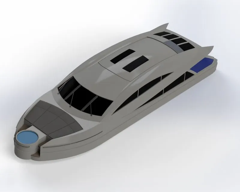
- Superstructure
- Radar Mast
All the models, but propeller and radar require a blueprint set up to have a reference while building the model for the yacht. In the Solidworks environment, every part model is made along with necessary decals and appearances, thereby producing a final assembly by giving suitable mates. For rendering purpose, a camera view is added and the final rendering is performed with different environments in Solidworks Visualize.
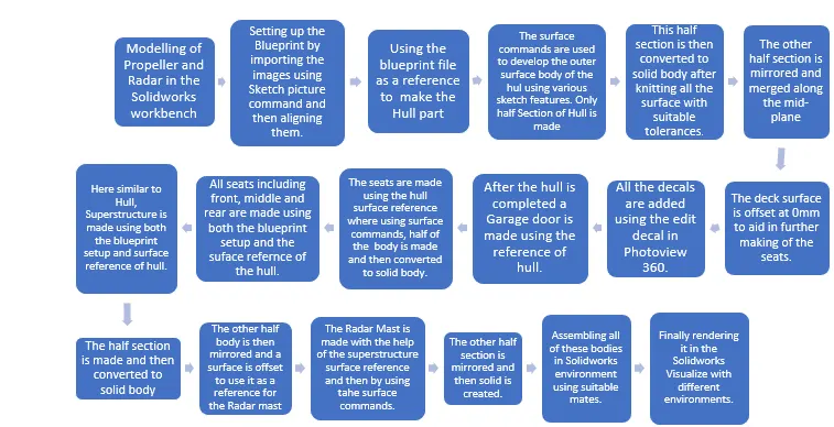
DESIGN METHODOLOGY: The approach to the project is in a subsequent manner where initiating from the sketching till rendering the assembly is conveniently performed. The flow chart resembles the sequence in which the process follows.
DESCRIPTION: The following parts which were listed above required various features and tools to fully define and construct the overall component. The sketches were ensured to be fully defined and the entities, in the end, were applied fillets to have a smoother curvature across the profile. The respective parts were designed along with the following steps:
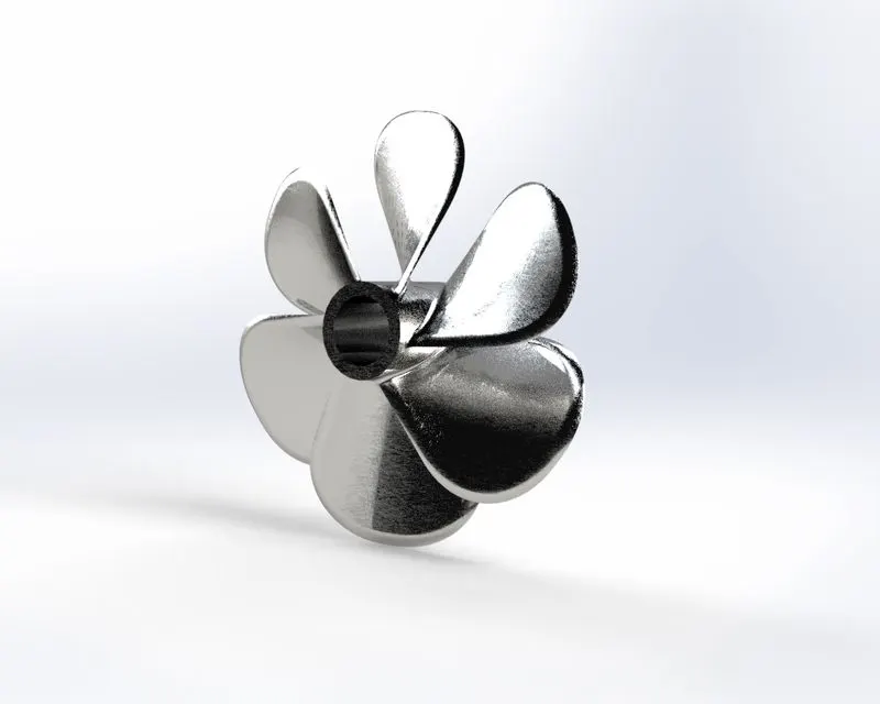
1. Propeller: A propeller is that part of a boat that is used to propel the body forward. It has a rotating shaft as well as rotating blades which when rotated by acting on the working fluid i.e. water produces a linear thrust.
- The hub of the propeller is made by making a sketch using line and spline commands.
- This sketch is then revolved using a revolved boss feature.
- An offset plane is created at a certain distance to the top plane to make the profile of the blade.
- Respective sketches are made and then using the surface loft feature, a surface in between these two areas is created which is the surface of the blade.
- Fillets are given to the periphery using a fillet feature.
- The hole in the hub is created using the cut extrude command.
- The blades are then circular patterned over the hub of the propeller using a circular pattern.
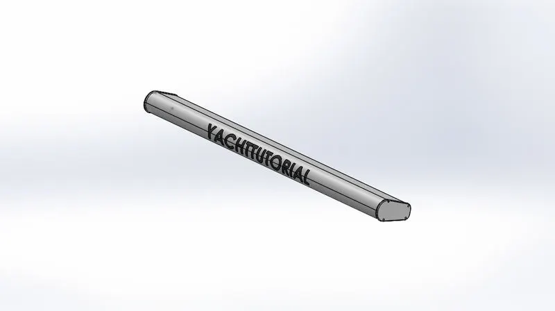
2. Radar: To navigate properly to avoid any collision, a radar is present over the radar mast that can receive signals and calculate rough estimations.
- A corner rectangle is created to make the profile for radar and then extruded using a boss-extrude feature.
- Fillets are added to give it a radar looking appearance using a fillet feature.
- To mount a screwface like is extruded on the end face using the boss-extrude feature.
- It is then applied fillet and then cut from the middle with a hexagonal profile using a cut-extrude feature.
- Three reference point sketches are created to pattern the same mount extrude along with these three other points. It is patterned with a sketch pattern feature.
- This half body is then mirrored along the midplane using a mid-plane feature.
- To mount this over the radar mast a hole is created on the bottom side using a cut extrude feature.
- To write a text over the radar we create a split line using a split lie feature and then emboss the text over the radar face.
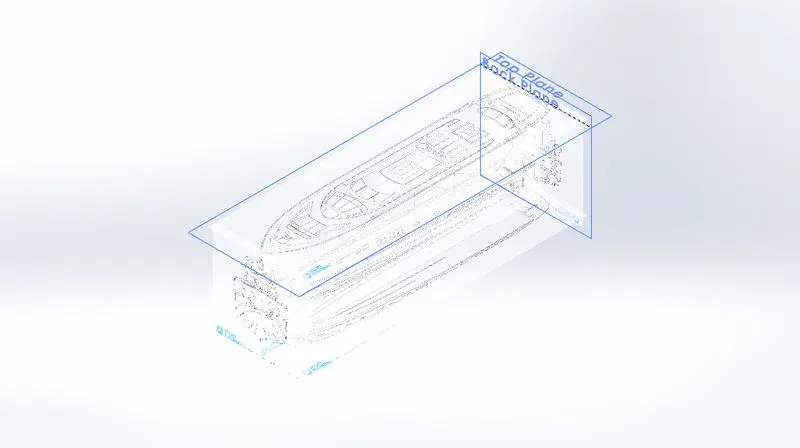
3. Blueprint setup: A blueprint reference is the positioning of every yacht image, including front, back, and side. top and bottom. All of these images are added using the sketch picture command and then positioned along the axis. This reference is further used to make a future profile of yacht such as hull, superstructure, seats and radar mast.
4. Hull: The boat's watertight enclosure is nothing but the hull which is the bottom section that also meets the waterline and the upper surface is the deck. It usually protects the boat from every condition, even machinery and prevents damage.
- The blueprint file is used as a reference to get the curve profiles as per the sketch image conveniently.
- Only half body is made along one side of the mid-plane so that it can be mirrored along the mid-plane at the end.
- Along the blueprint pictures of all the views are used to make the sketch entities.
- Curve profiles are generated using the spline feature and made in close agreement with that of the sketch picture reference, and then finally projected using a project feature command.
- Surfaces are generated along these curves using a surface loft feature.
- The end section is trimmed using a surface trim feature.
- To close this section from the other end as well as to mount the stabilizer, an extrude is generated using a surface extrude feature.
- Surface generated up till here are knitted with close tolerances using a knit surface feature.
- The extra surfaces are then trimmed along the way and the surface at the midsection is filled using a surface fill feature.
- These surfaces are then again knitted using a knit surface feature.
- This surface is then converted to a solid body using convert to solid while knitting. After this, the body is emptied with a certain thickness using a shell feature.
- The upper and the lower deck surfaces are made using the boss-extrude feature.
- The fillets and the chamfer are added to the lower deck surface using the fillet and chamfer command.
- The windows are generated on the outer surface of the hull using a reference plane and then a cut-extrude feature and a solid sweep are generated along the periphery using the solid sweep feature.
- The stairs in between the upper and lower deck surface are made using the boss-extrude feature.
- The parts over the deck surface using the boss-extrude feature, the spline command, the revolved feature, helix command and the parts which are repeated along the path are patterned using a linear pattern.
- To give the lower part of the hull friction in between the ways three boss-extrude bodies are made and then fillets are chamfers are added along its boundary using a fillet and chamfer command.
- The railings along the stairs are made using the solid sweep feature by creating a circular sketch profile at the end of the path.
- The railings over the hail are made by first making the railing reference sketch where lines are generated and then trimmed and extended using trim and extend entities command respectively.
- This reference is generated by using the project curve command.
- At the end of the profile path, a sketch is generated using a reference plane and then generating a sweep using a solid sweep feature.
- Some extra surfaces are protruded, which is needed to be deleted and removed using a delete face command.
- The forward end profile is also generated using the boss-extrude feature and subsequently, fillets are added using a fillet feature.
- To mount the stabilizer at the stern end a profile is made which lies below the waterline using the boss-extrude feature and then a sketch profile is made which is revolved and this stabilizer is mounted over this extruded profile. All the fillets are added using the fillet feature command.
- To mount those propellers a sketch profile is made on the midplane and its half-section is made and then revolved using a revolved feature. This profile is then patterned along the pattern direction line using the linear pattern feature.
- The next body to combine with the hull is the anchor which is located at the front end and is made using the boss-extrude feature. Only half of the section is made on one side of the plane and the other half is made using the mirror command. the fillets and chamfer are added to the extruded profiles using the fillet feature.
- The additional features to the hull at the rear end is made using the split line feature, cut extrude and boss- extrude command.
- After the half section of the body is made it is then mirrored along the midplane and the upper deck surface is offset using the surface offset feature to use it as a reference to make the seats and the superstructure.
- The stabilizer is also mirrored by using the mirror feature.
- Now the necessary decals are added such as the main floor, stair step and hatch front using the photoview 360 add-in and using the edit decals feature in render tools. All the necessary appearances are also added by giving different colours to the different sections.
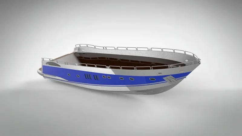
5. Front Seat: Seating arrangement is a place that can be acquired by oneself to have a seat. There can be different seating arrangements depending upon the type of yacht and also the space available. The three different seating arrangements are the front, middle and rear seat.
- Similar to that of a hull only a half-section is made along the midplane as a surface body and is then converted to solid and finally mirrored.
- The blueprint file is used as a reference to make the exact sketches of the curves and accurate positioning.
- The surface offset in the hull part is used as a reference for making the front seat which is inserted by using the Insert Part option in the insert toolbar. Here every option is deselected but the surface body.
- Firstly two different sketch profiles are made using the spline command and a swept surface is created using the surface sweep command.
- The two ends of the swept surface are then joined using another sketch profile which is extruded using the surface extrude feature.
- The extra surfaces coming out of the two disjointed faces are trimmed using the surface trim option which trims the surfaces either by keeping the ones which one needs or by deleting the ones which are not required.
- The open surface at the upper end is closed by using the surface fill command.
- Other reference sketches are created over these surfaces which resembles that of the blueprint image and then trimmed using the surface trim feature.
- The in-between voids formed are closed by forming a surface by using the surface-loft feature where the two profiles are selected along with guide curves to form a lofted surface.
- The surface underneath is closed by using the surface fill feature. All these surfaces are then knitted using the Surface knit option. The body is here converted to a solid body.
- After this necessary chamfer and fillets are given by using the filet and chamfer option.
- A sketch profile for making the remaining half is made on one end face which is then revolved using the revolve feature up to a certain angle.
- A thin surface extrude is created in between using the cut-extrude feature to divide them into two different bodies. The surface above this seat is offset as a sketch entity at a certain distance and then again revolved using a revolve command.
- The body is then cut along the midplane by cutting it through a profile with a cut extrude feature. The entire body is again cut with a thin extrude to separate it into four different bodies by using the cut-extrude feature.
- All the necessary fillets and chamfers are added by using the fillet and chamfer option and finally, the bodies are mirrored using the mirror feature.
- All the necessary appearances are also added by giving different colours to the different sections.
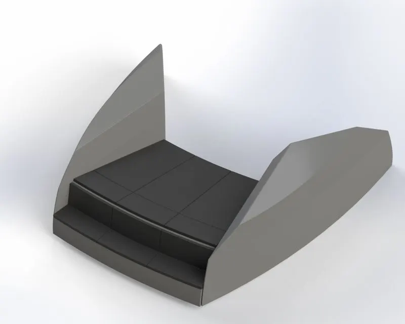
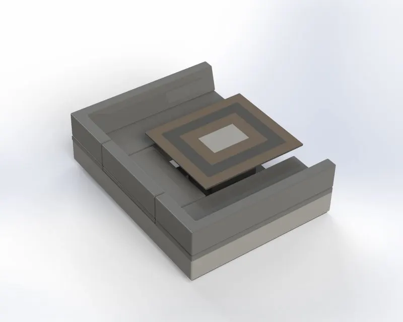
6. Middle seat: Middle seat is located in the middle of the yacht.
- The blueprint file is used as a reference to make the exact sketches of the curves and accurate positioning. Similar to that of a front seat only a half-section is made along the midplane as a solid body.
- The sketch reference is made resembling the blueprint top view and then extruded using the boss extrude feature.
- the same sketch is offset at a certain distance and then extruded back. Another surface is offset and is parted with a small gap and extruded using surface extrude.
- All of these surfaces and edges are given fillets and chamfer using the fillet and chamfer feature.
- These bodies are then mirrored using the mirror command along the midplane.
- The table in between is made using corner rectangles and offsetting them at a certain distance and finally extruding them using the boss-extrude feature.
- All the necessary appearances are also added by giving different colours to the different sections.
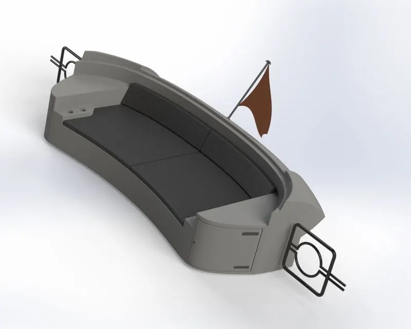
7. Rear seat: This is located at the stern end of the yacht.
- Both blueprint, as well as hull surface reference, is used to make the rear seat have accurate positioning of seat.
- Two sketch profiles are selected which are then joined by creating surface in between by using the surface sweep option. This surface is then offset at a certain distance.
- This offset surface is trimmed by using the surface trim option and then the remaining surface is extended by using the ruled surface option. These two surfaces are then knit using the knit surface feature.
- The unwanted part is trimmed using the trim feature. A reference plane is created to make a sketch using three points and another sketch perpendicular to it is made to create a path to make a surface using the surface sweep command.
- The unwanted intersecting surfaces are trimmed using the surface trim feature. Surfaces are knitted as well sketch profiles are created to make a close body by using the surface extrude options and knitting the surfaces subsequently.
- A 3-D sketch is created to create a lofted surface by using the surface loft option.
- All of these surfaces are knit and the remaining open sides are fixed either by creating surface extrudes or by creating lofted surfaces after creating 3-D sketches by using the surface loft feature.
- The small gap over the top surface is fixed by first extending the surface edges by using the surface extend options and then finally trimming the extra surfaces by using the surface trim option.
- All of these surfaces are knitted and a solid body is created by using the create solid tool.
- The seats are created by using the boss-extrude option and the drawer section is created by using the cut extrude command with an offset surface.
- The provisions to hold some commodities are created by using the cut extrude command and the rest surface and cushion area are created by offsetting the sketch and extruded using the boss-extrude tool.
- All the necessary chamfer and fillets are added by using the fillet and chamfer option.
- The side railings are created by making a reference plane and then creating sketched to create a solid body by using a solid sweep option. Only a half section is made and then mirrored by using the mirror feature and finally knitted and merged.
- All of these bodies are now mirrored along the midplane using the mirror command. the flagpost is created by first making a reference sketch and then revolving it by using the revolved feature.
- Four different 3-D sketches are created by making splines and then a surface loft is created by using the surface loft option.
- All the necessary appearances are also added by giving different colours to the different sections.
8. Superstructure: The body that emerges over the deck surface is the superstructure. It is an extended body that serves its purpose by accommodating people or any other thing.
- Similar to that of a hull, half of the section is created along the midplane and then converted to solid and then mirrored.
- Both blueprint, as well as the hull surface reference, are required to aid in making the profiles of the superstructure.
- Sketch profile of spline is created to extrude it using the surface extrude command and at its edge, a 3-D sketch is made and with the help of converted entity a surface is created using a surface sweep option.
- Both of these surfaces are knitted and fillet is added by using the knit surface and fillet feature respectively.
- Alon the end edge a ruled surface is created which is drafted inwards at an angle of 5 degrees by using a ruled surface option. This ruled surface is then trimmed using a surface trim option by making a spline profile at the midplane.
- Two sketch profiles of spline and line are created by using the midplane and top plane and the project curve feature is used to get the common curve. This same is repeated to get the second projected curve.
- Two 3-d Sketches are made to close these two projected curves and a surface in between them is formed by using the surface loft option. The other end is filled by first creating a 3-d sketch to close it and then filling it by using a fill-surface command.
- The upper surface is trimmed by making a 3-D sketch and then using the surface trim option. A new surface is generated by first making a reference plane at one end and then making a sketch over it and finally sweeping it by using the sweep surface feature.
- These surfaces are then knit using the knit surface command. Another reference plane is created to join the upper surface and lower extruded surface by creating a sketch and a converted entity and forming a surface by using a surface sweep option.
- On midplane, a converted entity is made in order to trim the extra surface by using the surface trim option. Similarly, a converted entity is used to create an extrude using the surface extrude feature.
- The extra intersecting surfaces are trimmed by using the surface trim command. Now, these surfaces are knit by using the knit surface command.
- A 3-D sketch is then created to create a surface fill at one end. Again this is knitted and the extra surface is removed by creating a sketch over the filled surface and trimming it by using the surface trim command.
- Then another 3-D sketch is created and a sketch on the previous reference plane is created to make a surface loft in between the ends by using the surface loft command. All of these surfaces are then knitted by using the knit surface command.
- After this using the midplane as a reference guide curves are made using the spine command to get the projected curves for the upper portion of the superstructure. The curves are then projected using the project curve option.
- Two 3-D sketches are generated to close the two guide curves to create a closed surface by using the surface loft feature. In a similar manner, sketches of curves are created and surfaces are generated by using the surface loft feature to complete the upper portion of the superstructure.
- To close the upper portion and the lower portion of the superstructure a ruled surface is generated by using the ruled surface option in the lower portion. These surfaces are then trimmed and knitted by using the surface trim and surface knit feature respectively.
- Surfaces are extended at the other end by using the surface extend feature and then trimmed using the surface trim command and then a 3-D sketch is generated to close the profile and make a surface by using the surface loft feature.
- Then surfaces are extended by using the ruled surface command and used to trim the rear portion of the superstructure.
- To close the gaps some sketch profiles are generated, which are then extruded by using the surface extrude command and then extra portions are trimmed by using the surface trim tool. These surfaces are then knitted using the surface knit feature.
- A close gap is still present at the inner end which is resolved by deleting the surface using the delete surface feature and then creating a 3-D sketch to close the gap and surface lofts are generated by using the surface loft feature. In the end, the other section is closed by using the surface fill feature.
- To make the front section of the superstructure convert entities from the upper portion along with other sketch references are used to create the surfaces by using the surface sweep command.
- Extra surfaces are trimmed and some surfaces are created by using the surface extrude option. These surfaces are then knitted using the surface knit feature.
- The jacuzzi section is used by making a sketch on the hull surface where the circular profile is extruded by using the boss-extrude feature. The inner portion is cut by using the cut-extrude feature. The fillets are added to both the inner and outer edges of the profile by using the fillet feature.
- A rectangular body is extruded cut by using the extrude cut feature to get only the half section of the jacuzzi. The stairs joining the front end and the jacuzzi are made by using the surface extrude feature.
- Surfaces are extended along the edge to trim the surfaces by using the surface extend and the surface trim feature respectively. Surfaces are knitted along the way by using the surface knit feature.
- To get the close body of the half section the dec surface is trimmed by using the surface trim option and the surface along the midplane is extruded by using the surface extrude surface feature and then trimmed by using the surface trim feature.
- These surfaces are knitted together and converted to solid by using the knit surface command.
- The other extra bodies are created by using the boss-extrude feature and merging the result every time. The handles across the front end and the rear end of the superstructure are made by using the solid sweep feature.
- The above window area is also generated by thickening the offset surface by using the thick surface command and then cutting it by using the cut extrude feature. Fillets are added by using the fillet feature.
- The back drawer section is also extrude cut by using the cut-extrude command and the handle is created by using the boss-extrude feature. The other necessary surface is made by using both boss-extrude and cut extrude commands.
- To close the jacuzzi section a surface extrude feature is used. Now the bodies of the superstructure mirrored by using the mirror option.
- Finally, the wipers are made by using the boss-extrude and solid sweep feature and the fillets and chamfers are added by using the fillet and chamfer feature.
- All the necessary appearances are also added by giving different colours to the different sections.
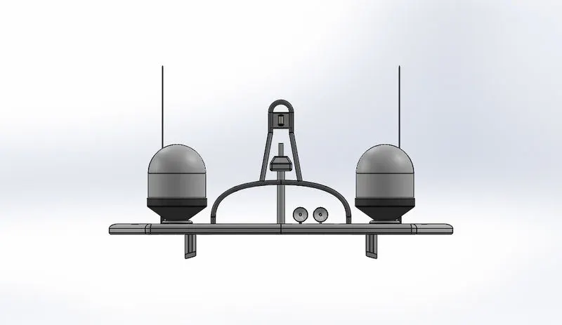
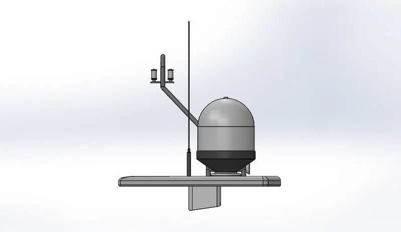
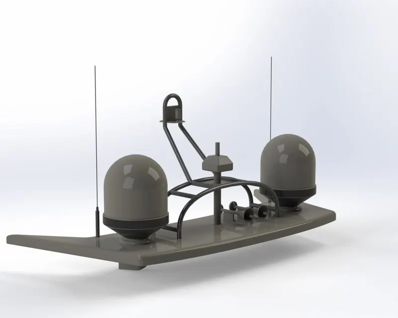
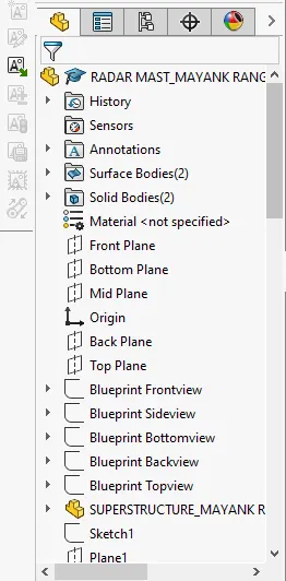
9. Radar mast: It is used to house the radar and also for locating the other ships and nearby land.
- Here both blueprint and the superstructure surface references are used to make the body of the radar mast. Only half of its section is made along the midplane and then mirrored at the end.
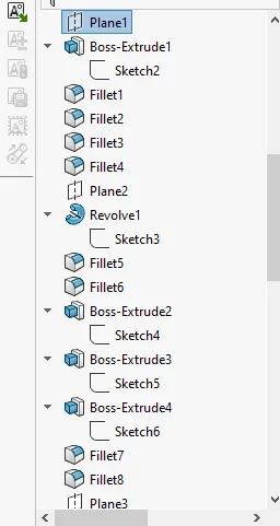
- A reference line is made on the midplane to make another plane for the reference sketches. On this plane along with a blueprint top view, sketches are made using the spline feature and extruded by using the boss-extrude feature.
- Fillets are given to the edges by using the fillet feature. A reference plane offset to the front plane is created.
- To get a revolved profile a sketch of half-section is made on this new plane in close agreement to the blueprint side view and then revolved by using the revolve boss command.
- Antennas are created by creating circular profiles and then extruding them by using the boss-extrude feature. Fillets are given to the edges by using the fillet feature
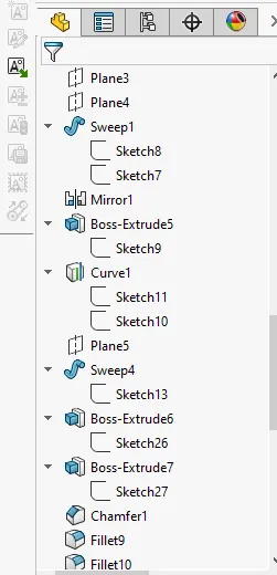
- To make the railings in the middle a sweep is generated by using the solid sweep option and then mirrored along the previous plane by using the mirror feature.
- To join these two railings a boss extrude is created in between them by using the boss-extrude features.
- Two profiles are created to get a projected curve by using the project curve option and a sweep is created on this path by using the solid sweep feature.
- Half sections are created on the base and then extruded by using the boss-extrude feature. Fillets and chamfers are added by using the fillet and chamfer feature.
- To make the mast light a profile for its base is extruded by using the boss-extrude feature and then fillets are given to the edges. Then a revolved half-section is made and then revolved for 180 degrees to make the mast light and this mast right is then mirrored using the mirror feature.
- To mount the base an extrude is made by using the boss-extrude feature at the bottom end face.
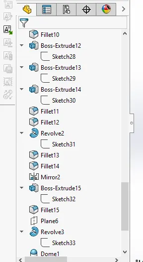
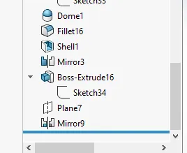
- To make the horn a half section profile is generated and then revolved by using the revolved feature. A dome is created at the other end by using the dome feature.
- A shell up to 2mm is created by using the hell feature. This body is then mirrored by using the mirror feature.
- To mount the horns an extrude is created by using the boss-extrude feature. This horn is then also mirrored along the new reference plane by using the mirror feature.
- All the necessary appearances are also added by giving different colours to the different sections.
ASSEMBLY AND RENDERING
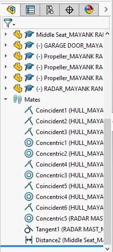
Since most of the parts were made with the reference of blueprint setup, that just after importing the part in the assembly workbench the part will acquire its position in the space. Some of the parts might still require some mates like concentric, coincident or distance mates etc. To add a camera view to the scene one can choose to select the add camera in the view toolbar where one can set up in accordance with one's perspective.
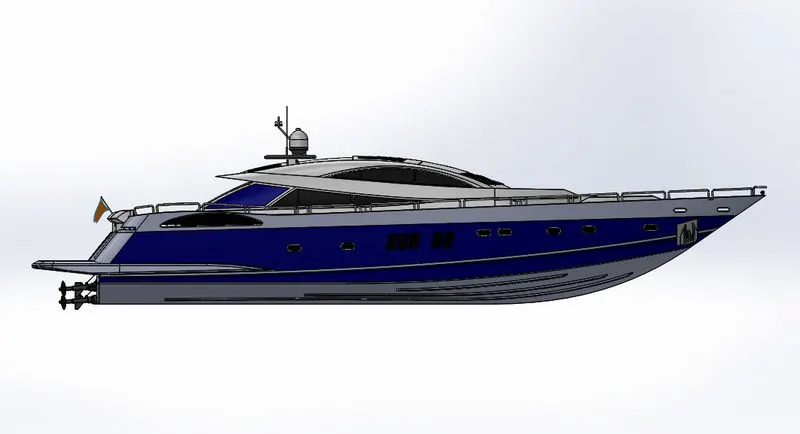
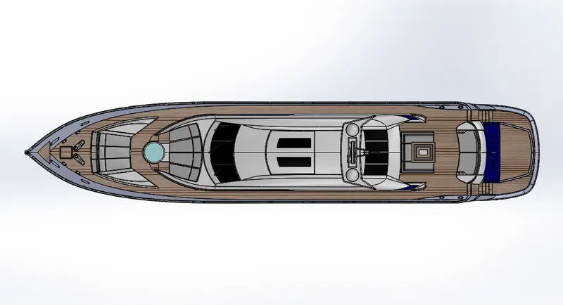
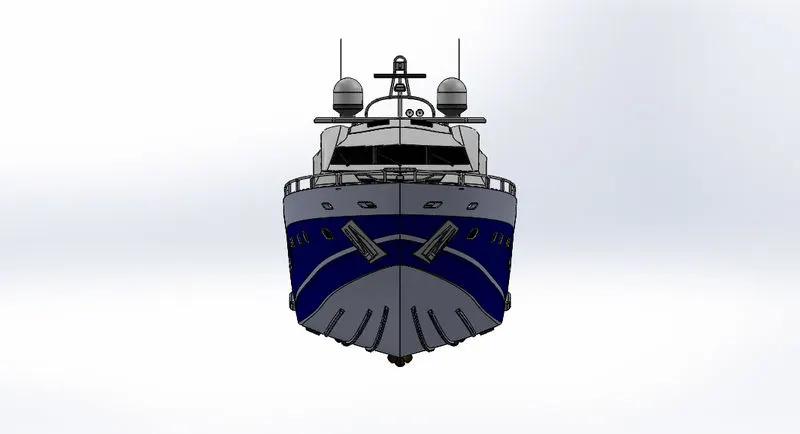
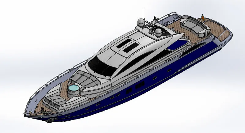
Cam view-
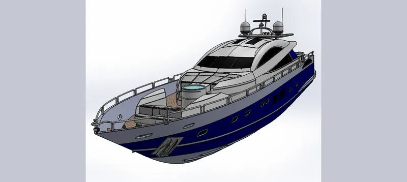
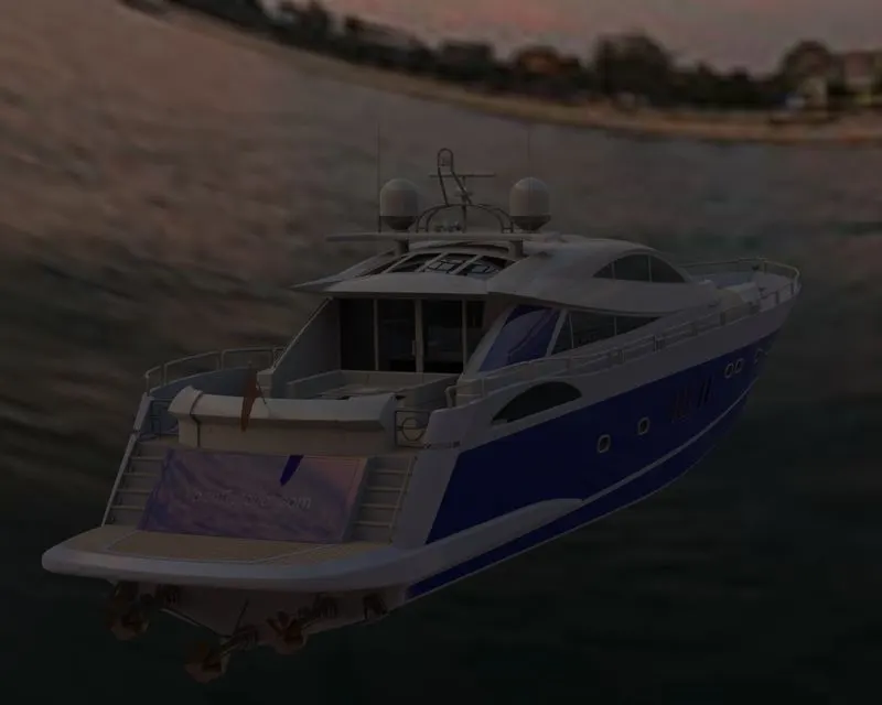
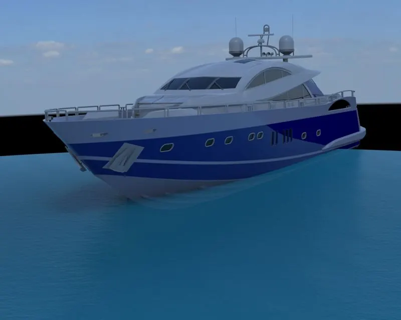
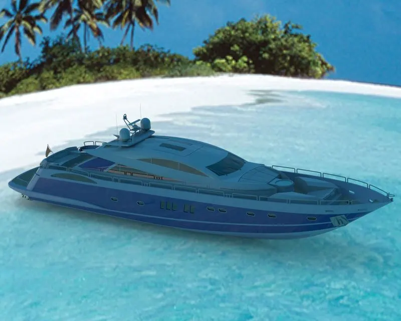
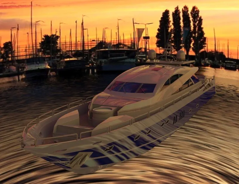
After the assembly of the yacht, one can render the yacht in different environments long with the positioning of the yachts in that environment as per their perspective. While creating a new project one has to import the assembly and then tweak among various option to finally render the assembly.
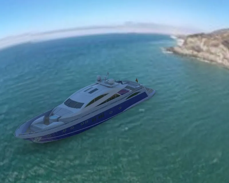
Conclusion: Hence the modelling, assembly and rendering of the Sunseeker yacht have been done successfully.