Radar Mast & Final Assembly of Yacht
Design, Assembly and Photo-Realistic Rendering of an American Predator Yacht
<!-- [if !supportLists]-->Ø <!--[endif]-->Objective:
The objective of this report is to discuss about the commands and techniques used to model, assemble and render different parts of the Yacht.
<!-- [if !supportLists]-->Ø <!--[endif]-->Introduction:
Solid Works is a 3D CAD software that is used to design 2D and 3D models. It helps to design products better faster and more time and cost efficiently.
In yacht modelling mostly depends on the surface modelling and some part depends on the part modelling. Scaled blueprints of the Yacht were set up for the modelling.
<!-- [if !supportLists]-->Ø <!--[endif]-->Design Methodology:
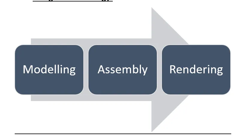
s
s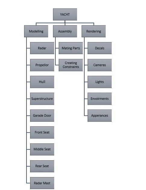
h
<!-- [if !supportLists]-->Ø <!--[endif]-->Tools and features Used:
<!-- [if !supportLists]-->· <!--[endif]-->2D Sketch: This command is used to create 2D sketches and then various relations and dimensions are given to fully define the drawing.
<!-- [if !supportLists]-->· <!--[endif]-->Boss Extrude: This command is used to extrude the selected sketch into a solid 3D part.
<!-- [if !supportLists]-->· <!--[endif]-->Trim: This command is used to remove any unwanted lines from the 2D drawing.
<!-- [if !supportLists]-->· <!--[endif]-->Offset: This is used to add sketch entities by offsetting faces, edges, curves, or sketch entities to a specified distance.
<!-- [if !supportLists]-->· <!--[endif]-->Convert Entities: This command is used to project the edges, loops, lines and various other entities into current segment.
<!-- [if !supportLists]-->· <!--[endif]-->Extrude cut: This is used to remove the excess material or specified material from a solid 3D part.
<!-- [if !supportLists]-->· <!--[endif]-->Revolve: This command is used for making solid bodies by revolving the 2D sketch along an axis.
<!-- [if !supportLists]-->· <!--[endif]-->Revolve Cut: This command Cuts a solid model by revolving a solid profile around an axis.
<!-- [if !supportLists]-->· <!--[endif]-->Swept Boss: This feature is used to create a profile by selecting a closed or open diagram known as path and another line or sketch along which the boss will be creates known as path.
<!-- [if !supportLists]-->· <!--[endif]-->Loft: This command creates the feature by taking into account the transitions between the various profiles.
<!-- [if !supportLists]-->· <!--[endif]-->Fillet: This command is used to smoothen the pointed edges.
<!-- [if !supportLists]-->· <!--[endif]-->Chamfer: This command is used to join to adjacent faces using a line.
<!-- [if !supportLists]-->· <!--[endif]-->Surface Extrude: This feature helps us is a 3D surface from a 2D sketch.
<!-- [if !supportLists]-->· <!--[endif]-->Ruled Surface: This feature created the ruled surface among the selected edges.
<!-- [if !supportLists]-->· <!--[endif]-->Extend Surface: This feature extends the selected surface in a particular direction.
<!-- [if !supportLists]-->· <!--[endif]-->Surface Fill: This feature fills the area/ path between edges, sketches or curves.
<!-- [if !supportLists]-->· <!--[endif]-->Boundary Surface: This feature creates a boundary surface between profiles in two directions.
<!-- [if !supportLists]-->· <!--[endif]-->Lofted Surface: Same as loft command only difference being that the part created using this command will be a surface instead of a solid.
<!-- [if !supportLists]-->· <!--[endif]-->Offset Surface: This feature creates offset surfaces using one or more contiguous faces.
<!-- [if !supportLists]-->· <!--[endif]-->Surface Trim: This feature is used to trim one or more intersecting surfaces by selecting a cutting edge as the trim tool.
<!-- [if !supportLists]-->· <!--[endif]-->Swept Surface: Creates a surface feature by sweeping an open or closed profile along an open or closed path.
<!-- [if !supportLists]-->· <!--[endif]-->Surface Knit: Combines/ fills the gap between two or more adjacent, non-intersecting surfaces together.
<!-- [if !supportLists]-->· <!--[endif]-->Shell: This feature removes material from a solid body to create a thin-walled feature.
<!-- [if !supportLists]-->· <!--[endif]-->Mirror: This feature allows to place the same part or sketch along a particular axis or plane.
<!-- [if !supportLists]-->· <!--[endif]-->Split Line: Projects a sketch to curved or planar faces, creating multiple separate faces.
<!-- [if !supportLists]-->· <!--[endif]-->Linear Pattern: Patterns features, faces & bodies in one or two linear directions.
<!-- [if !supportLists]-->· <!--[endif]-->Circular Pattern: Patterns features, faces & bodies around an axis.
<!-- [if !supportLists]-->· <!--[endif]-->Projected Curve: This feature is used to project a sketched curve onto a face or sketch.
<!-- [if !supportLists]-->Ø <!--[endif]-->Image Part Files
<!-- [if !supportLists]-->v<!--[endif]-->Propeller:
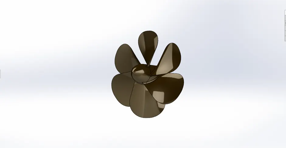
Tools/Techniques Used:
<!-- [if !supportLists]-->· <!--[endif]-->Revolve
<!-- [if !supportLists]-->· <!--[endif]-->Loft
<!-- [if !supportLists]-->· <!--[endif]-->Fillet
<!-- [if !supportLists]-->· <!--[endif]-->Fillet
<!-- [if !supportLists]-->· <!--[endif]-->Cut Extrude
<!-- [if !supportLists]-->· <!--[endif]-->Circular Pattern
<!-- [if !supportLists]-->v<!--[endif]-->Hull:
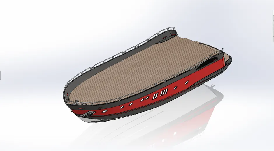
Tools and Techniques:
<!-- [if !supportLists]-->· <!--[endif]-->Projected Curve
<!-- [if !supportLists]-->· <!--[endif]-->Surface loft
<!-- [if !supportLists]-->· <!--[endif]-->Surface Trim
<!-- [if !supportLists]-->· <!--[endif]-->Surface Extrude
<!-- [if !supportLists]-->· <!--[endif]-->Surface Knit
<!-- [if !supportLists]-->· <!--[endif]-->Surface Fill
<!-- [if !supportLists]-->· <!--[endif]-->Shell
<!-- [if !supportLists]-->· <!--[endif]-->Fillet
<!-- [if !supportLists]-->· <!--[endif]-->Chamfer
<!-- [if !supportLists]-->· <!--[endif]-->Sweep
<!-- [if !supportLists]-->· <!--[endif]-->Dome
<!-- [if !supportLists]-->· <!--[endif]-->Helix/Spiral
<!-- [if !supportLists]-->· <!--[endif]-->Curve Pattern
<!-- [if !supportLists]-->· <!--[endif]-->Linear Pattern
<!-- [if !supportLists]-->· <!--[endif]-->Mirror
<!-- [if !supportLists]-->· <!--[endif]-->Surface Offset
<!-- [if !supportLists]-->v <!--[endif]-->Superstructure:
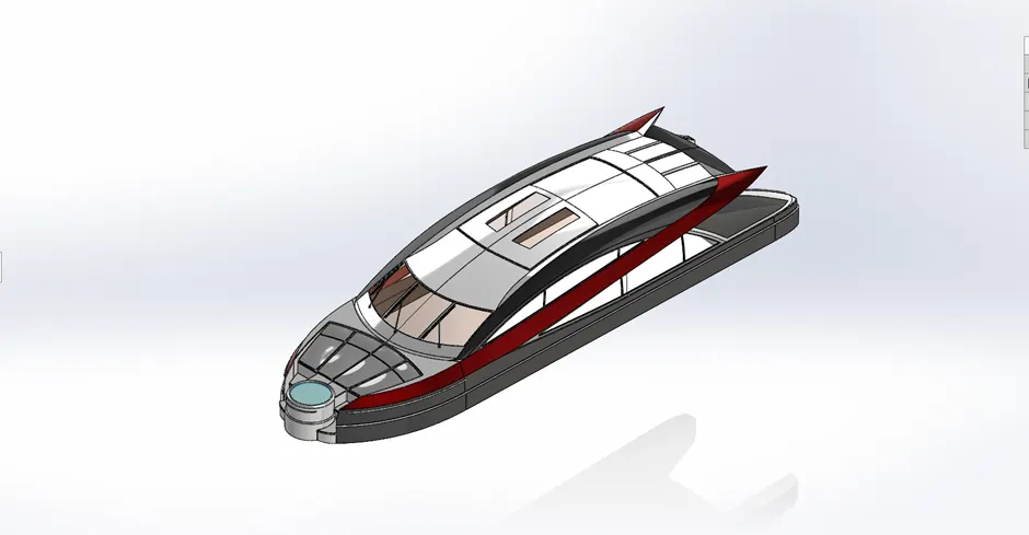
Tools & Techniques:
<!-- [if !supportLists]-->· <!--[endif]-->Blueprint Setup
<!-- [if !supportLists]-->· <!--[endif]-->Surface Extrude
<!-- [if !supportLists]-->· <!--[endif]-->Surface Sweep
<!-- [if !supportLists]-->· <!--[endif]-->Surface Knit
<!-- [if !supportLists]-->· <!--[endif]-->Fillet
<!-- [if !supportLists]-->· <!--[endif]-->Ruled Surface
<!-- [if !supportLists]-->· <!--[endif]-->Surface Trim
<!-- [if !supportLists]-->· <!--[endif]-->Projected Curve
<!-- [if !supportLists]-->· <!--[endif]-->Surface Loft
<!-- [if !supportLists]-->· <!--[endif]-->Surface Fill
<!-- [if !supportLists]-->· <!--[endif]-->Boss Extrude
<!-- [if !supportLists]-->· <!--[endif]-->Mirror
<!-- [if !supportLists]-->· <!--[endif]-->3D sketch
<!-- [if !supportLists]-->· <!--[endif]-->Thicken
<!-- [if !supportLists]-->v <!--[endif]-->Radar
Tools and Techniques:
<!-- [if !supportLists]-->·<!--[endif]--> Boss Extrude
<!-- [if !supportLists]-->·<!--[endif]--> Fillet
<!-- [if !supportLists]-->·<!--[endif]--> Cut Extrude
<!-- [if !supportLists]-->·<!--[endif]--> Sketch Pattern
<!-- [if !supportLists]-->·<!--[endif]--> Mirror
<!-- [if !supportLists]-->·<!--[endif]--> Split line
<!-- [if !supportLists]-->v <!--[endif]-->Radar Mast:
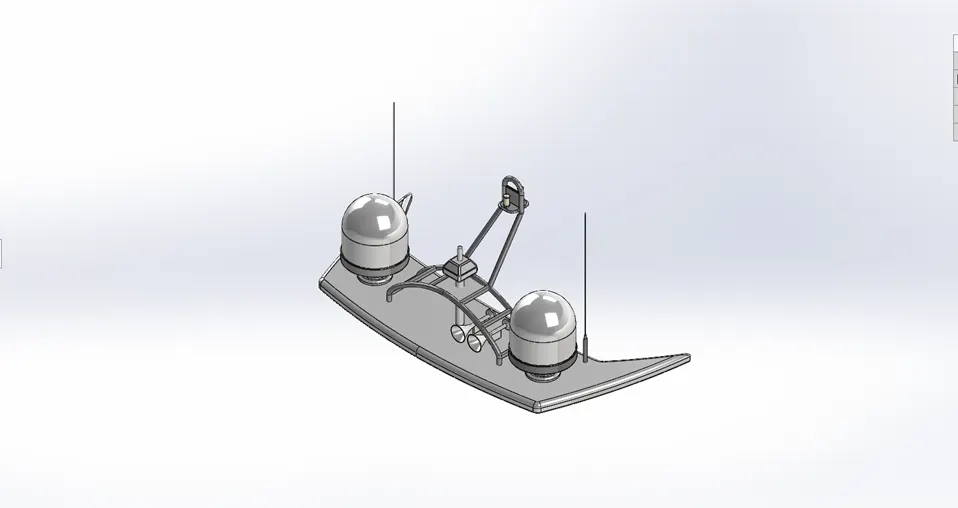
Tools and Techniques
<!-- [if !supportLists]-->· <!--[endif]-->Blue Print Setup
<!-- [if !supportLists]-->· <!--[endif]-->Boss Extrude
<!-- [if !supportLists]-->· <!--[endif]-->Fillet
<!-- [if !supportLists]-->· <!--[endif]-->Revolve
<!-- [if !supportLists]-->· <!--[endif]-->Sweep
<!-- [if !supportLists]-->· <!--[endif]-->Mirror
<!-- [if !supportLists]-->· <!--[endif]-->Projected Curve
<!-- [if !supportLists]-->· <!--[endif]-->Dome
<!-- [if !supportLists]-->· <!--[endif]-->Shell
<!-- [if !supportLists]-->v <!--[endif]-->Back Door
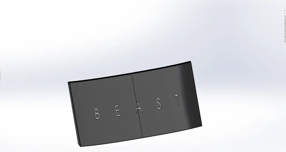
Tools and Techniques
<!-- [if !supportLists]-->· <!--[endif]-->Extrude Cut
<!-- [if !supportLists]-->· <!--[endif]-->Shell
<!-- [if !supportLists]-->· <!--[endif]-->Fillet
<!-- [if !supportLists]-->· <!--[endif]-->Mirror
<!-- [if !supportLists]-->v <!--[endif]-->Front Seat:
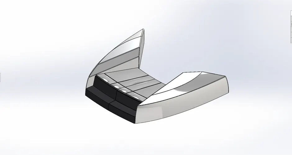
Tools and Techniques:
<!-- [if !supportLists]-->· <!--[endif]-->Surface Sweep
<!-- [if !supportLists]-->· <!--[endif]-->Surface Extrude
<!-- [if !supportLists]-->· <!--[endif]-->Surface Trim
<!-- [if !supportLists]-->· <!--[endif]-->Surface Fill
<!-- [if !supportLists]-->· <!--[endif]-->Surface Loft
<!-- [if !supportLists]-->· <!--[endif]-->Surface Knit
<!-- [if !supportLists]-->· <!--[endif]-->Chamfer
<!-- [if !supportLists]-->· <!--[endif]-->Surface Trim
<!-- [if !supportLists]-->· <!--[endif]-->Revolve
<!-- [if !supportLists]-->· <!--[endif]-->Extrude Cut
<!-- [if !supportLists]-->· <!--[endif]-->Fillet
<!-- [if !supportLists]-->· <!--[endif]-->Mirror
<!-- [if !supportLists]-->· <!--[endif]-->Dome
<!-- [if !supportLists]-->v <!--[endif]-->Middle Seat
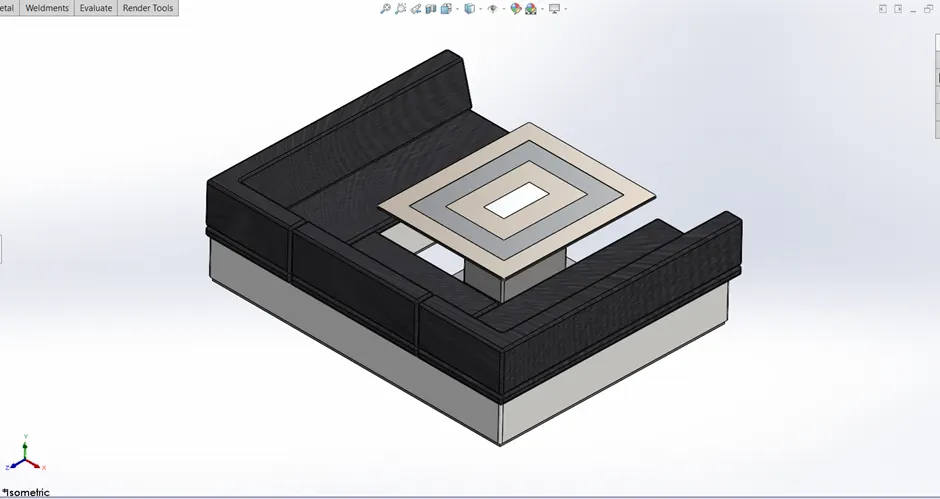
Tools and Techniques:
<!-- [if !supportLists]-->· <!--[endif]-->Boss Extrude
<!-- [if !supportLists]-->· <!--[endif]-->Chamfer
<!-- [if !supportLists]-->· <!--[endif]-->Fillet
<!-- [if !supportLists]-->· <!--[endif]-->Mirror
<!-- [if !supportLists]-->· <!--[endif]-->Boss Extrude
<!-- [if !supportLists]-->· <!--[endif]-->Extrude Cut
<!-- [if !supportLists]-->v <!--[endif]-->Rear Seat
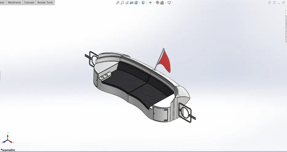
Tools and Techniques
<!-- [if !supportLists]-->· <!--[endif]-->Surface Sweep
<!-- [if !supportLists]-->· <!--[endif]-->Surface Offset
<!-- [if !supportLists]-->· <!--[endif]-->Surface Trim
<!-- [if !supportLists]-->· <!--[endif]-->Ruled Surface
<!-- [if !supportLists]-->· <!--[endif]-->Surface Knit
<!-- [if !supportLists]-->· <!--[endif]-->Surface Sweep
<!-- [if !supportLists]-->· <!--[endif]-->Surface Extend
<!-- [if !supportLists]-->· <!--[endif]-->Surface Extrude
<!-- [if !supportLists]-->· <!--[endif]-->Surface Loft
<!-- [if !supportLists]-->· <!--[endif]-->Boss Extrude
<!-- [if !supportLists]-->· <!--[endif]-->Cut Extrude
<!-- [if !supportLists]-->· <!--[endif]-->Fillet
<!-- [if !supportLists]-->· <!--[endif]-->Sweep
<!-- [if !supportLists]-->· <!--[endif]-->Chamfer
<!-- [if !supportLists]-->· <!--[endif]-->Mirror
<!-- [if !supportLists]-->· <!--[endif]-->Revolve
<!-- [if !supportLists]-->Ø <!--[endif]-->Different Screenshots of the Yacht Assembly
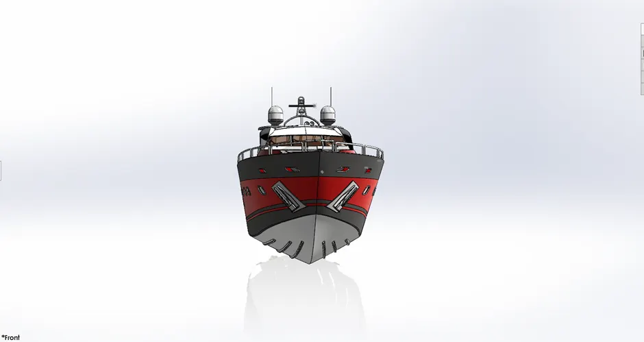
<!-- [if !supportLists]-->v <!--[endif]-->Front View
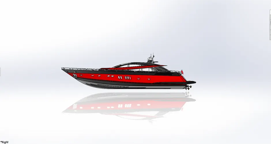
<!-- [if !supportLists]-->v <!--[endif]-->Side View
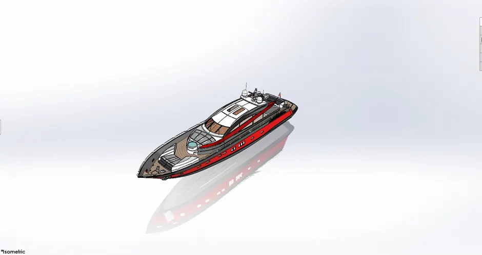
<!-- [if !supportLists]-->v <!--[endif]-->Isometric View
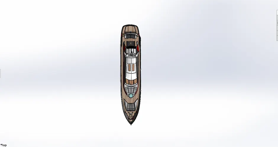
<!-- [if !supportLists]-->v <!--[endif]-->Top View
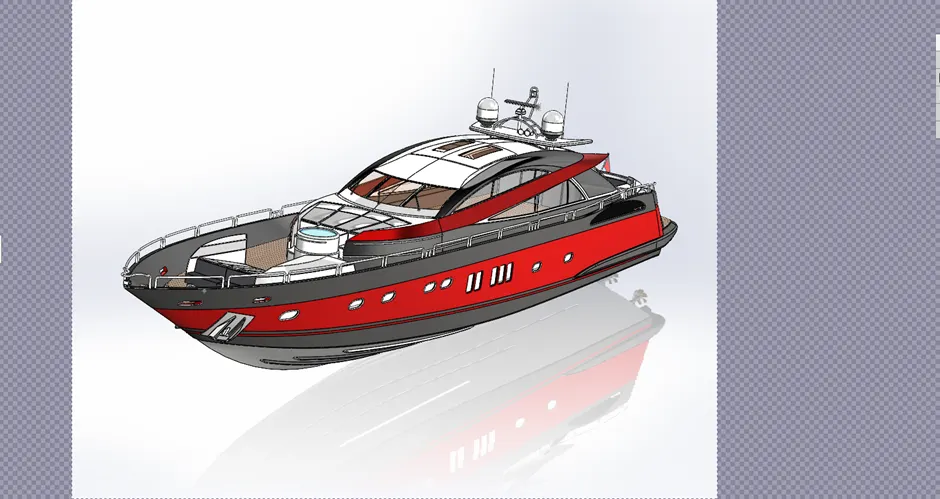
<!-- [if !supportLists]-->v <!--[endif]--> Camera View
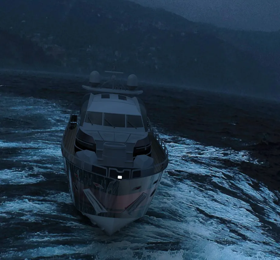
<!-- [if !supportLists]-->Ø <!--[endif]--> Rendered Images
<!-- [if !supportLists]-->Ø <!--[endif]-->Conclusion
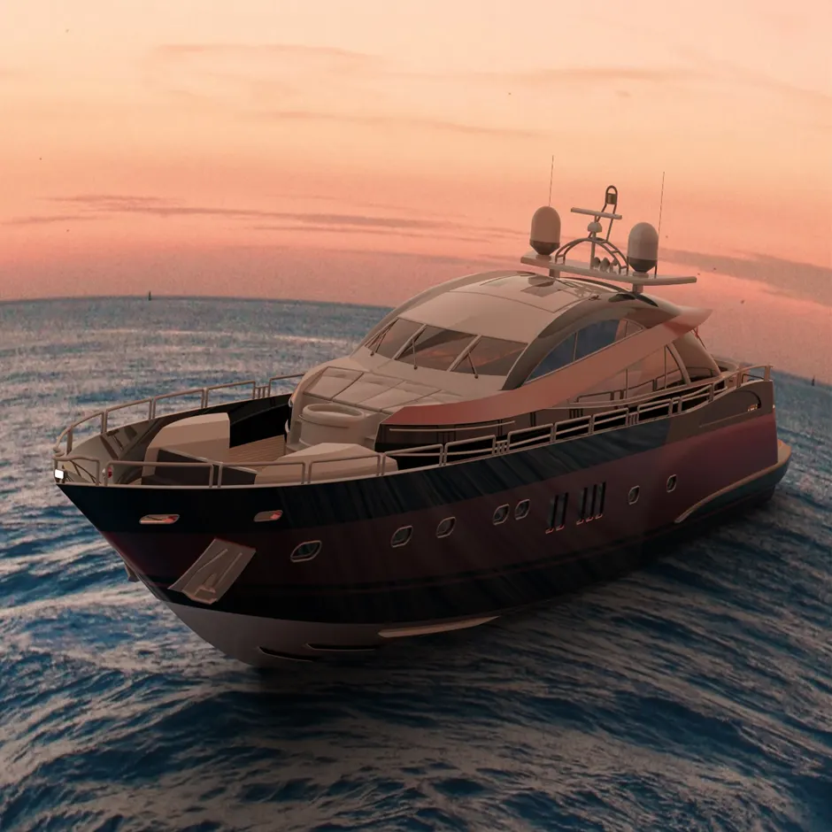
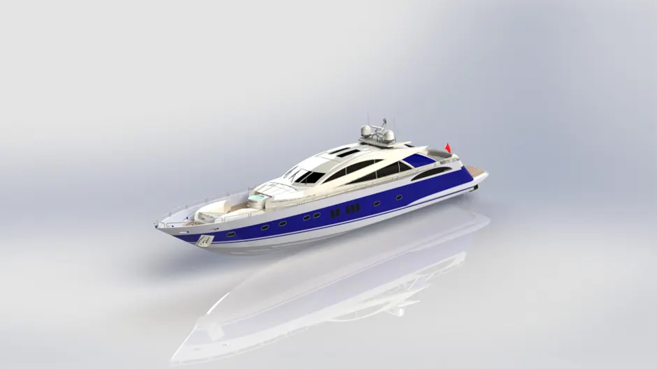
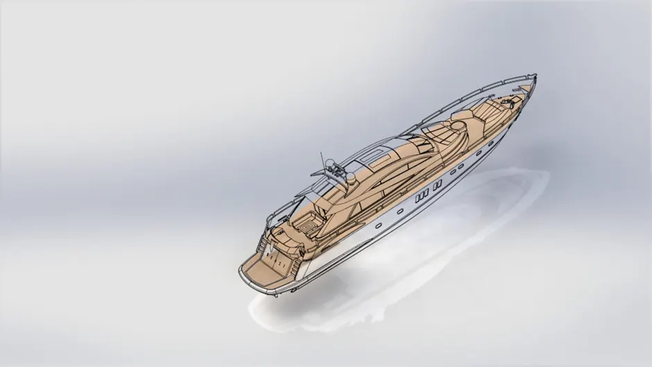
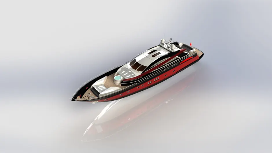
These are the result of the correct design technique used for the simulation and rendering of Yachts in SolidWorks using Photo view 360 and solid works Visualize software.