Radar Mast & Final Assembly of Yacht
YACHT DESIGN
Introduction:
In this report we had discussed about the modelling, assembling and rendering of SUNSEEKER PREDATOR YACHT and included with tools which are used to model the YACHT as well as the quick explanation of each parts.
Design Methodology:
The method used here is Bottom-up designing procedure as follows,
1. Designing of piece parts and its appearence.
2. Assembly of Designed Yacht parts.
3. Applying Decals, Camera setup and scenes compositions.
4. Final Rendering.
The Following parts to be Modelled individually:
- Propeller
- Radar
- Hull
- Garage Door
- Front seat
- Middle Seat
- Rear Seat
- Super Structure
- Radar Mast
Tools Used
Creating a 2D sketch :
A 2D sketch is the base to create a 3D model.It is usually created on the X-axis & Y-axis. This includes lines, circles, rectangles, splines, etc.
Trim :
The trim command is used to remove or erase the extra edges of intersecting lines on a 2D sketch.
Offset:
Adds sketch entities by offsetting faces, edges, curves, or sketch entities to a specified distance.
Convert Entities :
Converts selected model edges or sketch entities into current sketch segments.
Boss Extrude :
It extrudes a sketch or selected sketch contours in one or two directions to create a solid feature.
Extruded Cut :
Extrude cut is a feature which helps to remove materials from the 3D model. It is just opposite to extrude boss/base feature, because it cuts a sketch profile while extruding. It can cut in both directions and mainly used for creating holes, channels, slots etc.
Revolved Cut : Cuts a solid model by revolving a solid profile around an axis.
Revolved Boss : Revolves a sketch or selected sketch contours around an axis to create a solid feature.
Swept Boss :This feature sweeps a closed profile along an open or closed path to create a solid feature.
Loft : The loft feature creates a shape by making transitions between multiple profiles and guides curves thus allowing to create complex geometry with a single tool.
Dome : A dome is a rounded vault forming the outside face of a body or structure, typically with a circular base.
Combine : This feature is used to combine two or more solid bodies together.
Fillet : A fillet is used to connect two adjacent faces using a smooth tangent arc.
Chamfer : The chamfer command is used to connect two adjacent faces using an inclined line.
Surface Extrude :
Using this feature, we can extrude the boundary edges of a face of a solid body or edges of a surface body in a customized direction. A planar surface body is used to extrude its boundary edges.
Ruled Surface : This feature inserts a ruled surface from the selected edges.
Extend Surface : Extends the edge, multiple edges or the face on a surface, based on end conditions & extension type.
Surface Fill : Constructs a surface patch within a boundary defined by existing model edges, sketches or curves.
Boundary Surface : Creates a boundary surface between profiles in two directions.
Lofted Surface : Creates a lofted surface between two or more profiles.
Offset Surface : Creates offset surfaces using one or more contiguous faces.
Surface Trim : This feature is used to trim one or more intersecting surfaces by selecting a cutting edge as the trim tool.
Swept Surface : Creates a surface feature by sweeping an open or closed profile along an open or closed path.
Surface Knit : Combines two or more adjacent, non-intersecting surfaces together.
Shell : This feature removes material from a solid body to create a thin-walled feature.
Mirror : This allows to mirror features, faces & bodies along a face or a plane.
Split Line : Projects a sketch to curved or planar faces, creating multiple separate faces.
Linear Pattern : Patterns features, faces & bodies in one or two linear directions.
Circular Pattern : Patterns features, faces & bodies around an axis.
Projected Curve : This feature is used to project a sketched curve onto a face or sketch.
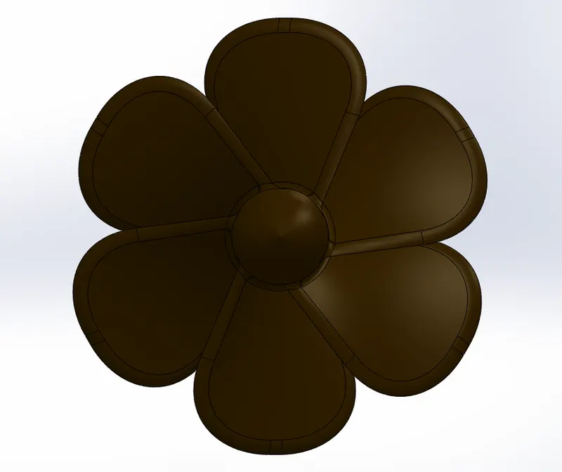
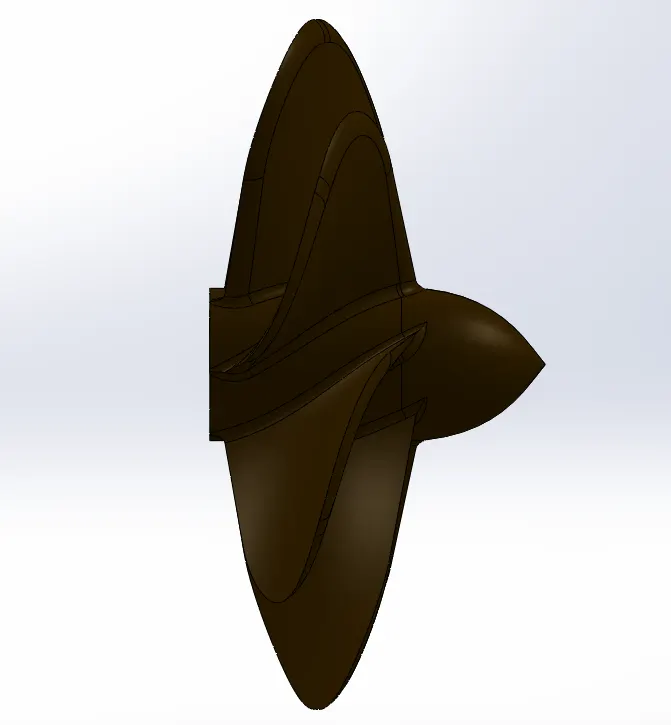
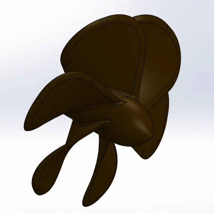
1. Propeller
Features used
- Sketch
- Revolve
- Loft
- Cut Extrude
- Circular Pattern
- Fillet
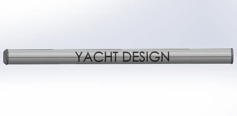
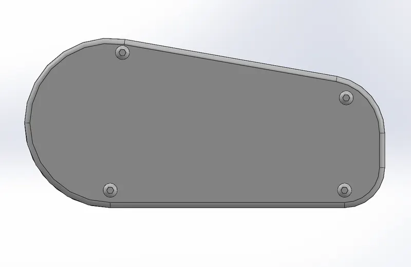
2. Radar
Features used
- Boss Extrude
- Cut Extrude
- Sketch Pattern
- Split Line
- Mirror
- Fillet
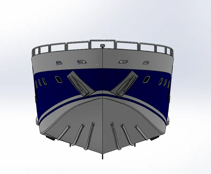
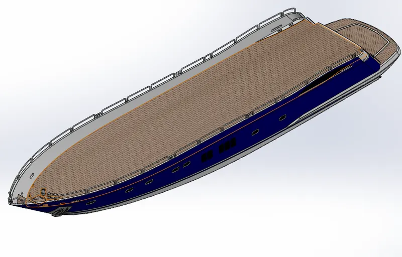
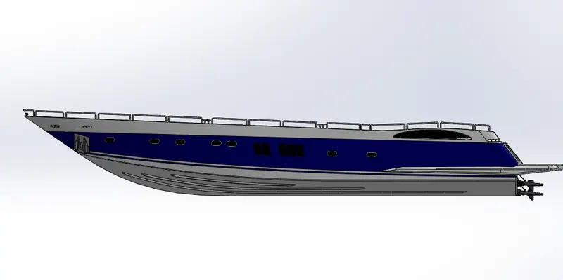
3. Hull
Features used
- Sketch
- Project Curve
- Surface Loft
- Surface Trim
- Surface Extrude
- Surface Knit
- Surface Fill
- Shell
- Cut Extrude
- Fillet
- Chamfer
- Sweep
- Boss Extrude
- Revolve
- Dome
- Helix/Spiral
- Linear Pattern
- Add/Delete Face
- Thin Extrude
- Thin cut Extrude
- Split
- Split Line
- Offset Surface
- Mirror
4. Garage Door
The garage door body was 'Split' from the hull and imported separately for modelling. The garage door was mated with the hull garage during the assembly.
Features used
- Cut Extrude
- Shell
- Mirror
- Fillet
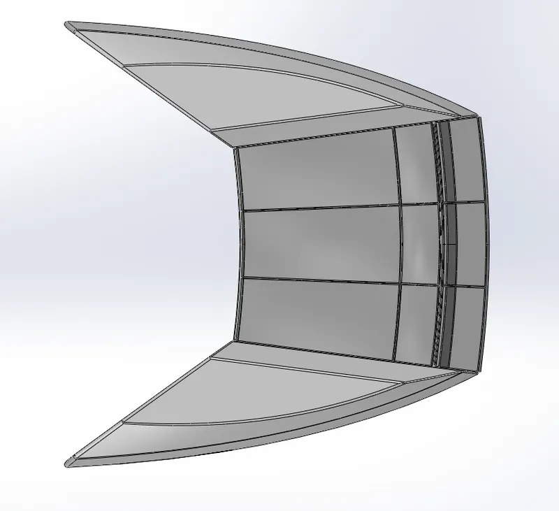
5. Front Seat
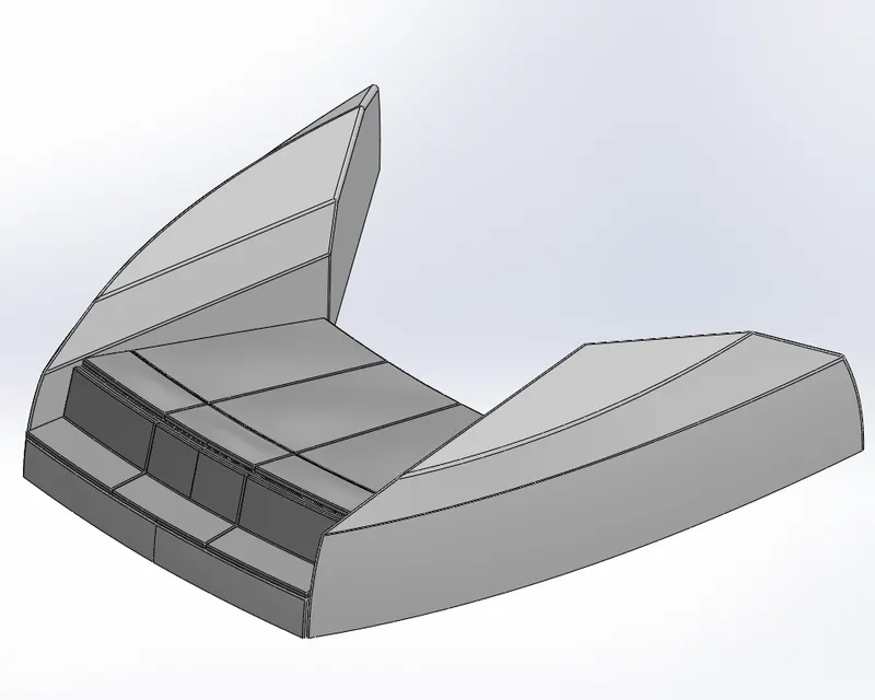
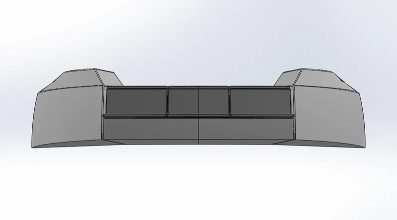
Front seat was placed in front of the Superstructure on the hull. It was designed after importing the deck surface of the Hull as interface surface.
Features used
- Surface Sweep
- Surface Extrude
- Surface Fill
- Surface Trim
- Surface Loft
- Surface Knit
- Revolve
- Cut Extrude
- Cut Thin Extrude
- Chamfer
- Fillet
- Mirror
- Dome
6. Middle Seat
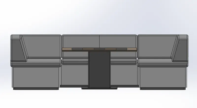
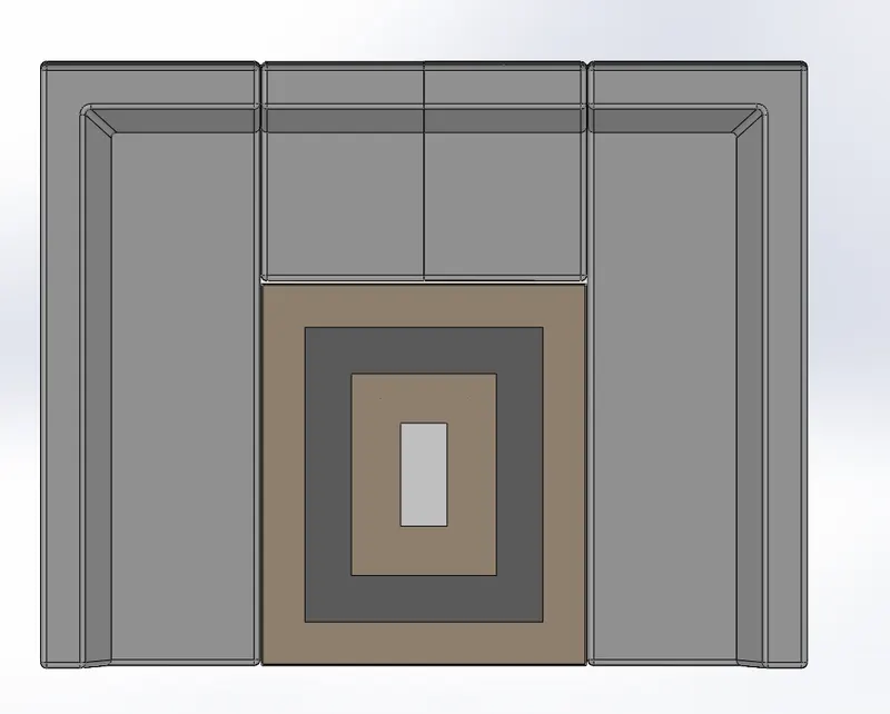
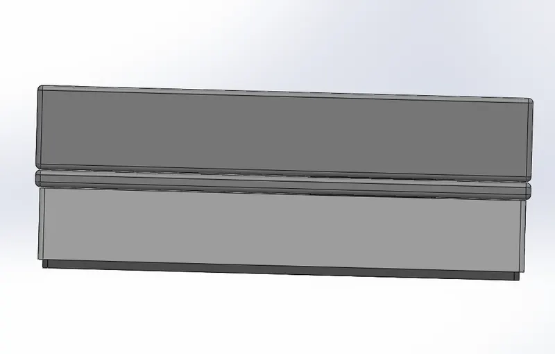
Features used
- Boss Extrude
- Mirror
- Cut Extrude
- Chamfer
- Fillet
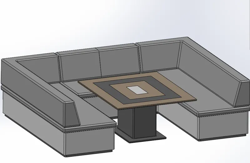
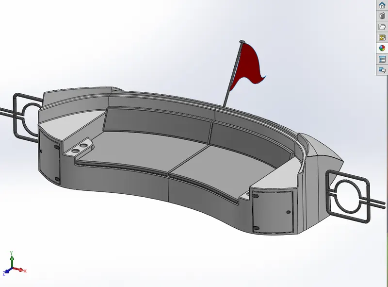
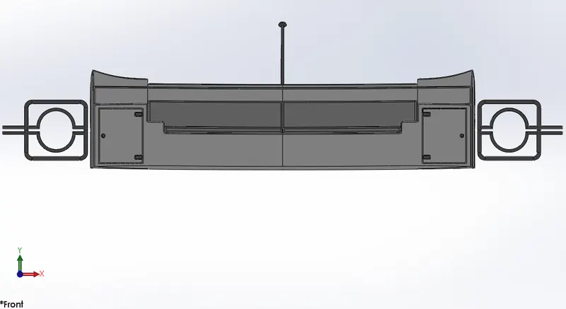
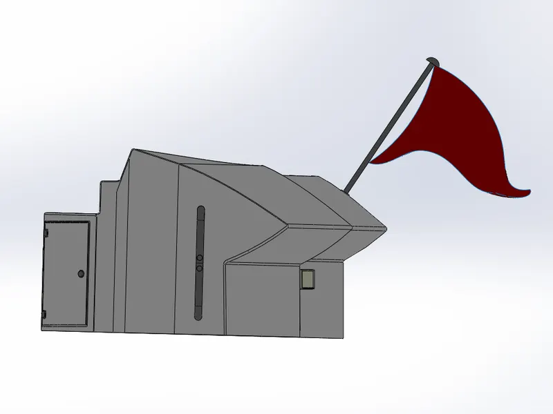
7. Rear Seat
Rear seat was placed over the garage behind the Superstructure. It was designed after importing the deck surface of the Hull as interface surface.
Features used
- Surface Sweep
- Surface Offset
- Surface Trim
- Ruled Surface
- Surface Knit
- Surface Extend
- Surface Extrude
- Surface Loft
- Boss Extrude
- Cut extrude
- Chamfer
- Boss Sweep
- Mirror
- Revolve
- Fillet
8. Superstructure
Features used
- Surface Sweep
- Surface Knit
- Project Curve
- Surface loft
- Surface Fill
- Surface Extrude
- Surface Trim
- Ruled Surface
- Surface Extend
- Fillet
- Cut-Extrude
- Face Delete
- Boss Extrude
- Surface Offset
- Thickness
- Dome
- Boss Sweep
- Extrude Thin
- Split Line
- Mirror
- Chamfer
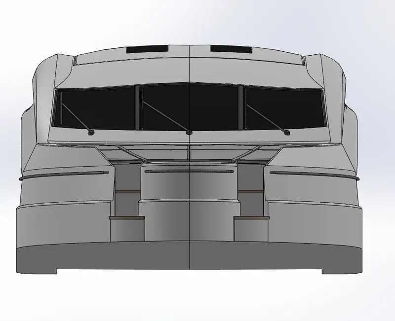
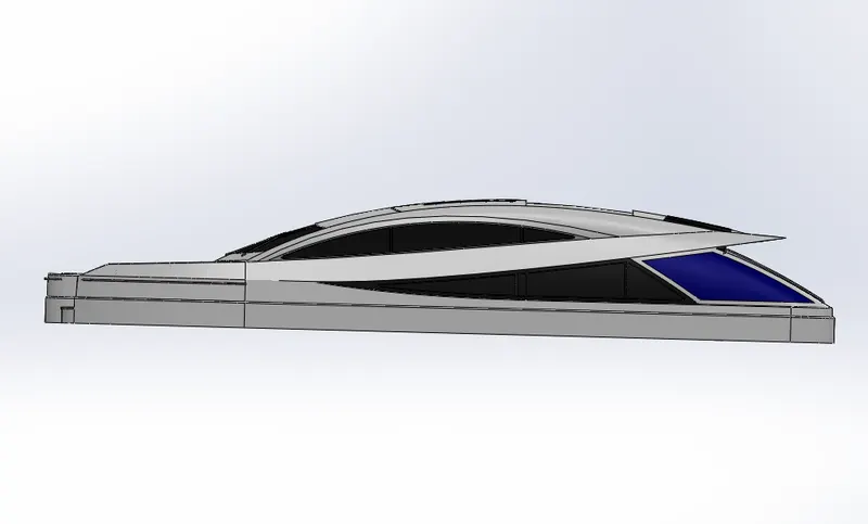
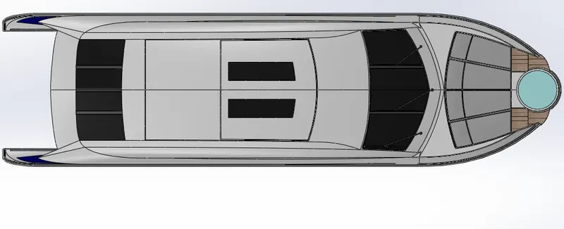
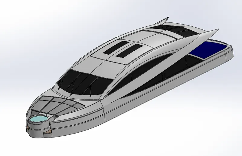
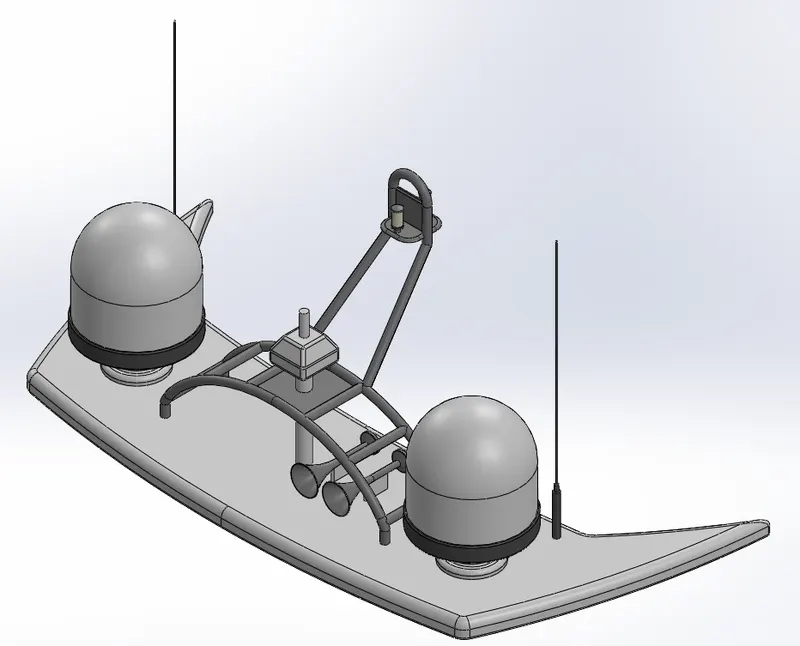
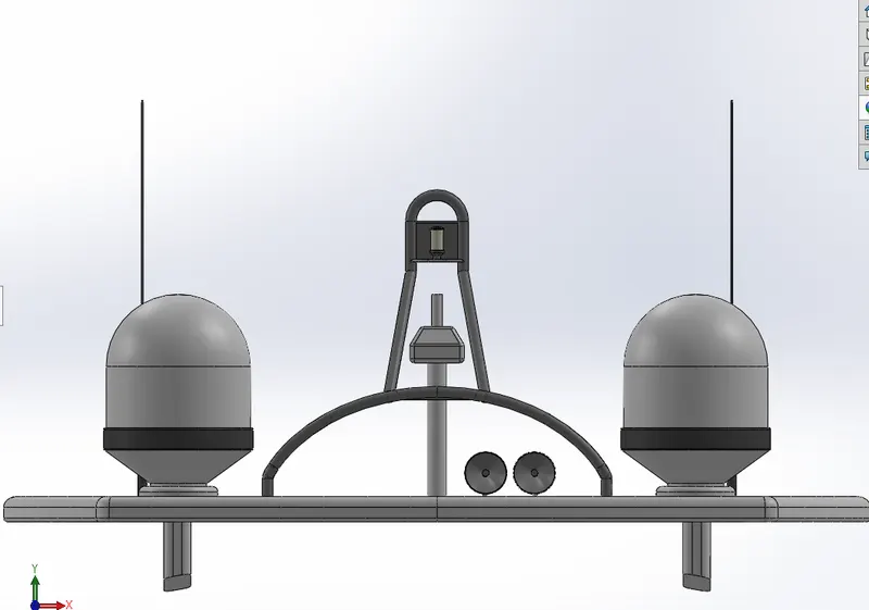
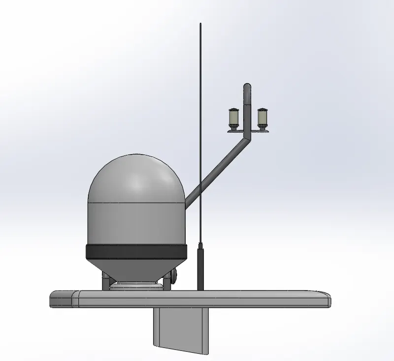
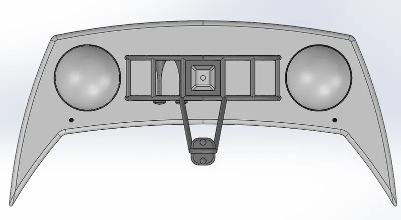
9. Radar Mast
The Radar mast supports the radar, antennas, satellite domes and lights. It was designed after importing the top surface of the Superstructure as interface surface.
Features used
- Boss Extrude
- Revolve
- Fillet
- Boss Sweep
- Mirror
- Project Curve
- Chamfer
- Mirror
ASSEMBLY :
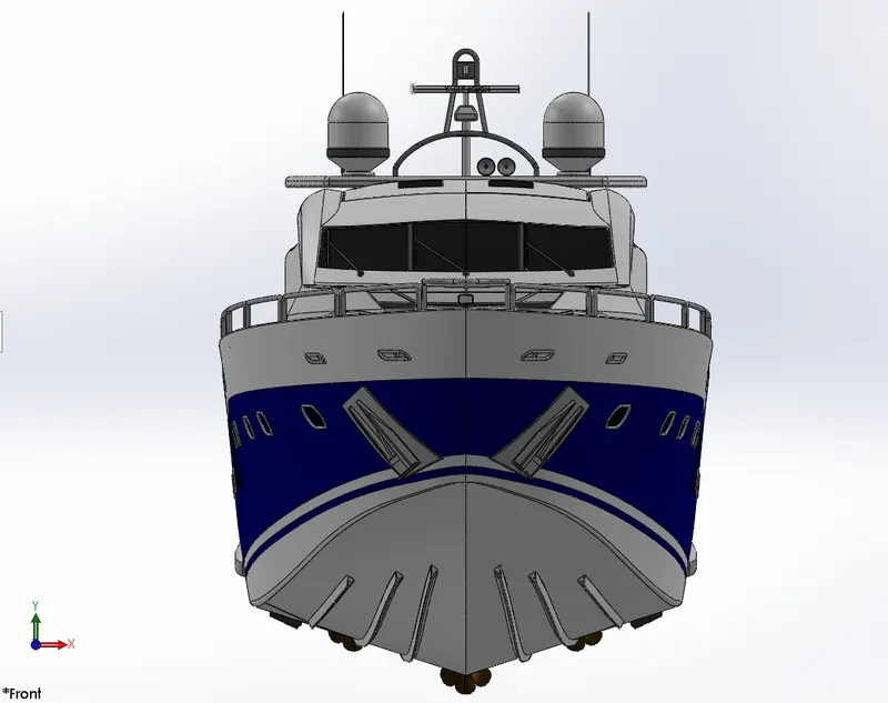
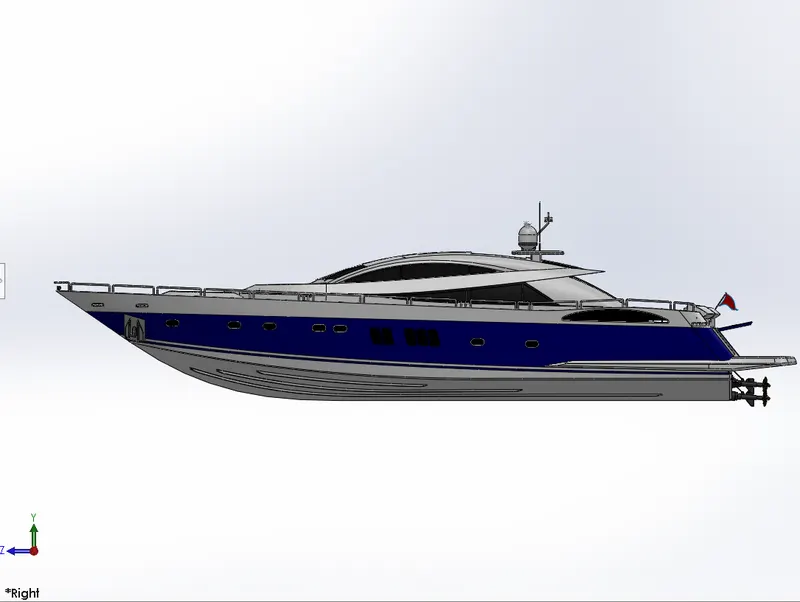
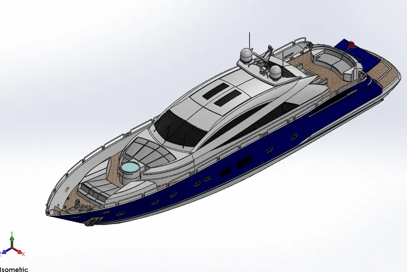
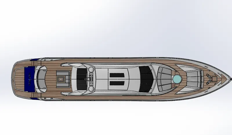
As all the parts are designed using solidworks part, now in the Assembly is used to assemble the parts of the YATCH by giving appropiate MATES with required realtive conditions.
YATCH is assembled in the assembly workbench with fix position by the help of applying mates.
RENDERING :
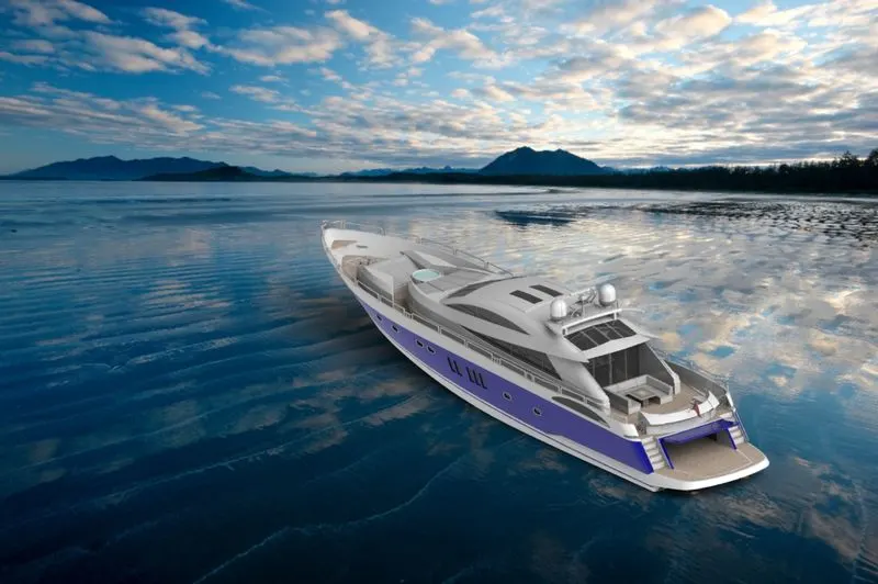
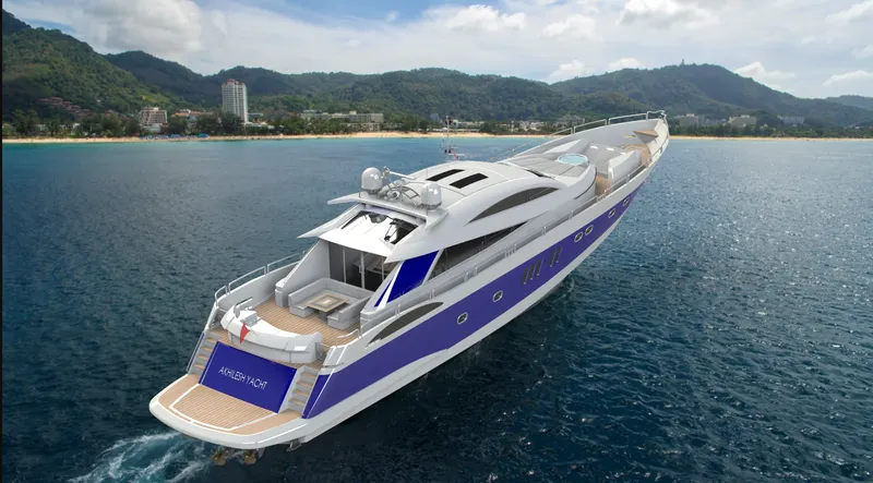
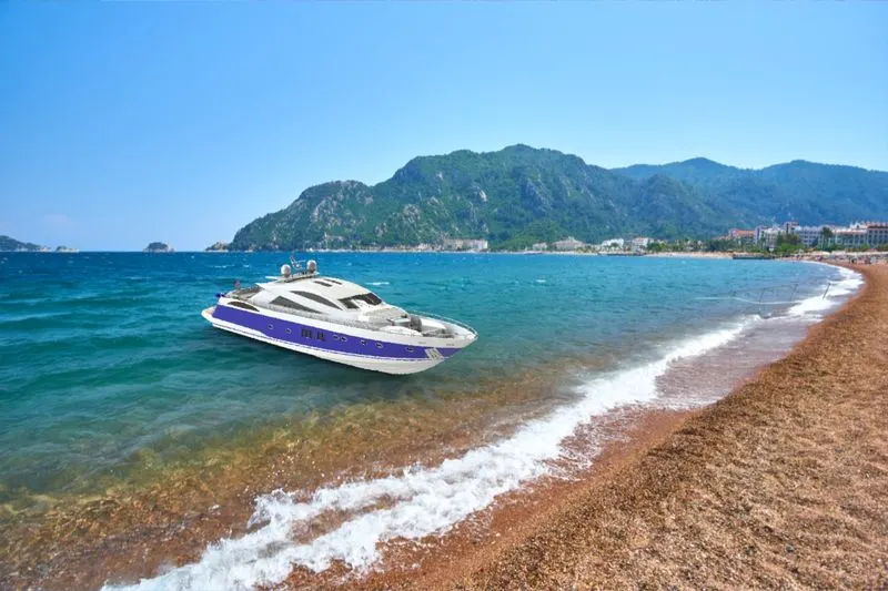
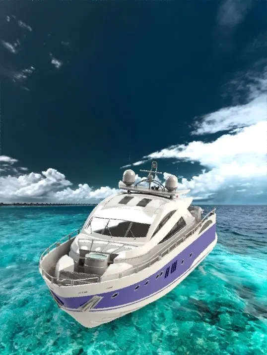
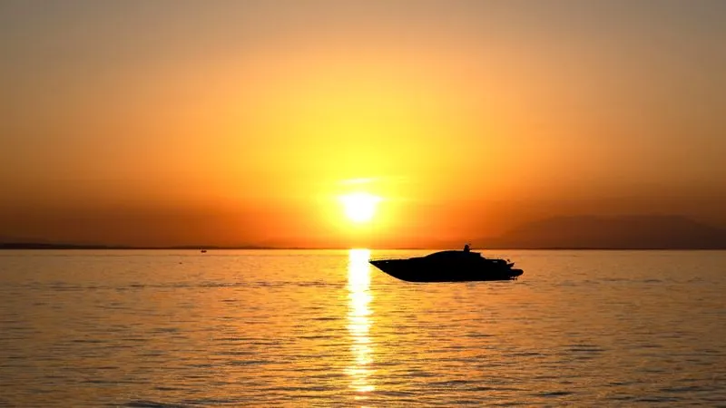
Conclusion:
- The parts of the Yacht are modeled. The parts are inserted into the assembly environment and the Yacht is assembled.
- These are the result of the correct design technique for the simulation and rendering of Yachts in Solidworks using Photoview 360