Radar Mast & Final Assembly of Yacht
Question 1
DEVELOPING SOLID MODELS AND RENDERS OF PREDATOR YACHT
Objective:
- The primary objective is to create various components of the yacht using suitable solid/surface modelling features that will fasten the designing process.
- Understanding the importance of a fully defined sketch that help us to alter the dimensions anytime you want without any error.
- Understanding the assembling process of the yacht.
- Creating high quality rendered images on SolidWorks photoview360 and SolidWorks visualize by experimenting with different appearances, scenes, rendering properties, etc.
Introduction:
This project explains the designing process of the sunseeker predator yacht and rendering the model to obtain photorealistic images of the yacht.
Design Methodology:
We will be an inside-out approach to model the predator yacht.
- First, individual components will be designed using suitable dimensions which will help us create a fully defined sketch.
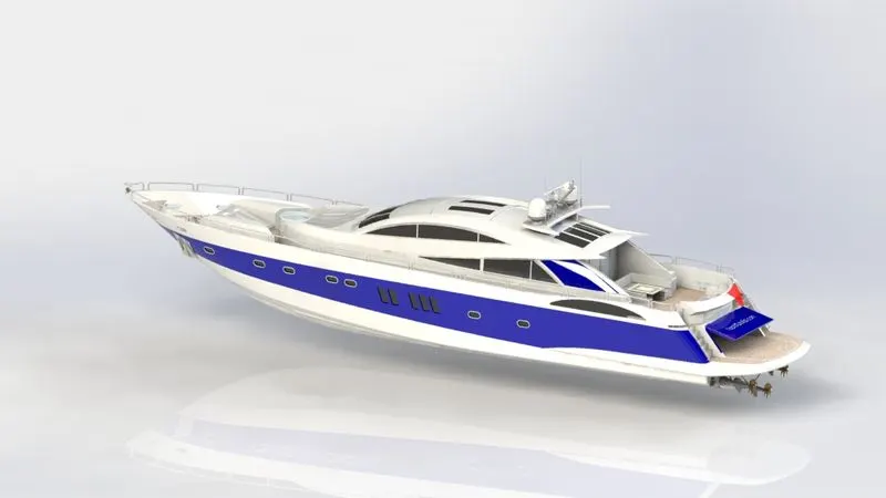
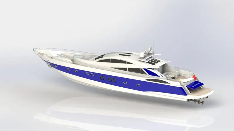
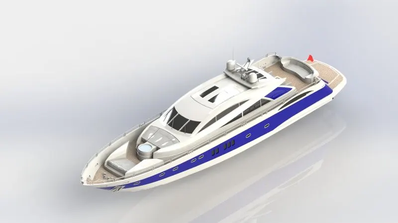
- Assembling the components with proper mates and relations to get the final yacht model.
- Adding decals to the model and setting up scenes to obtain realistic rendered images.
- Lastly, render the model with varieties of scene setup and appearance on SolidWorks photoview360 and Solidworks visualize to get photorealistic images.
-
List of components in predator yacht model:
- Propeller
- Radar
- Hull
- Garage Door
- Front Seat
- Middle Seat
- Rear Seat
- Superstructure
- Radar Mast
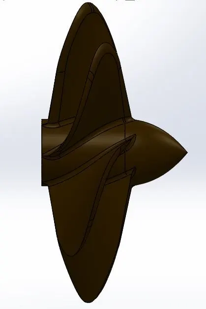
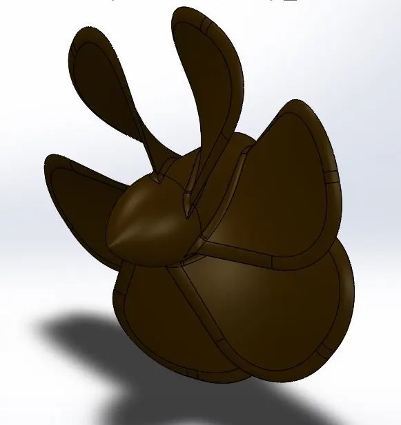
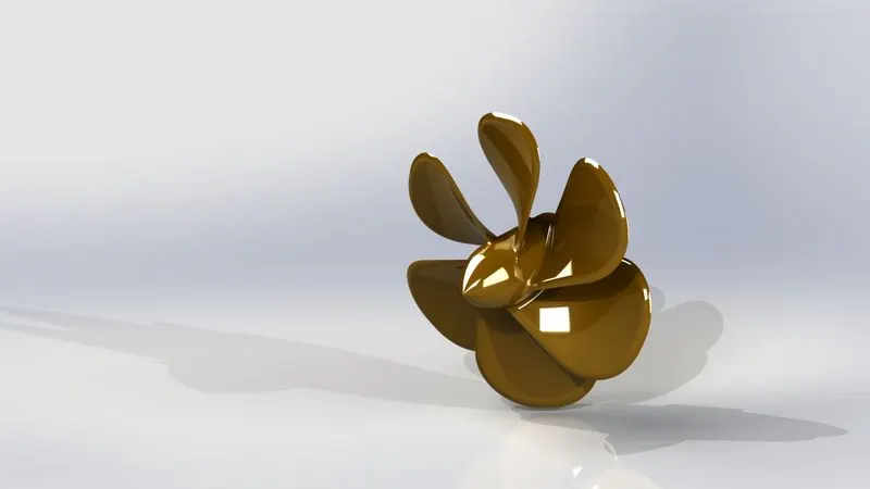
A. Propeller
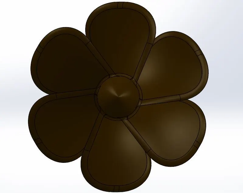
A propeller is a rotating structure that generates thrust force to propel the ship. This thrust force is acted on the blades by the water when the power generated by the engine is consumed by the propeller.
Procedures and features used:
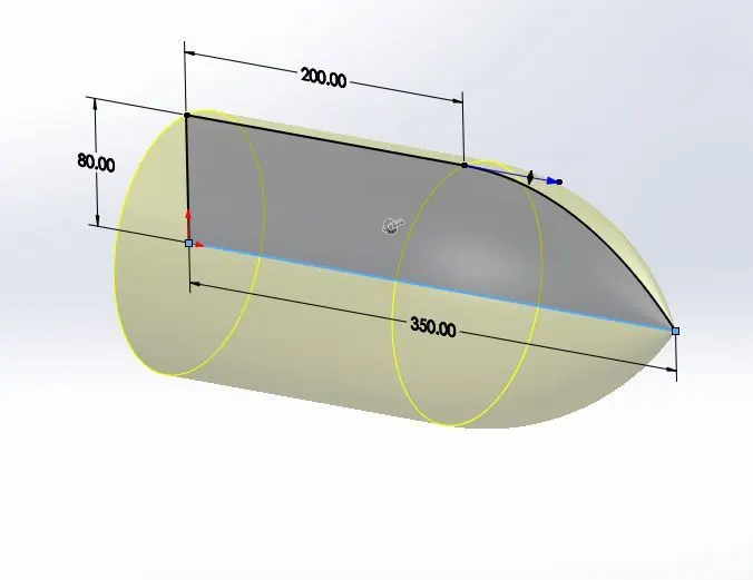
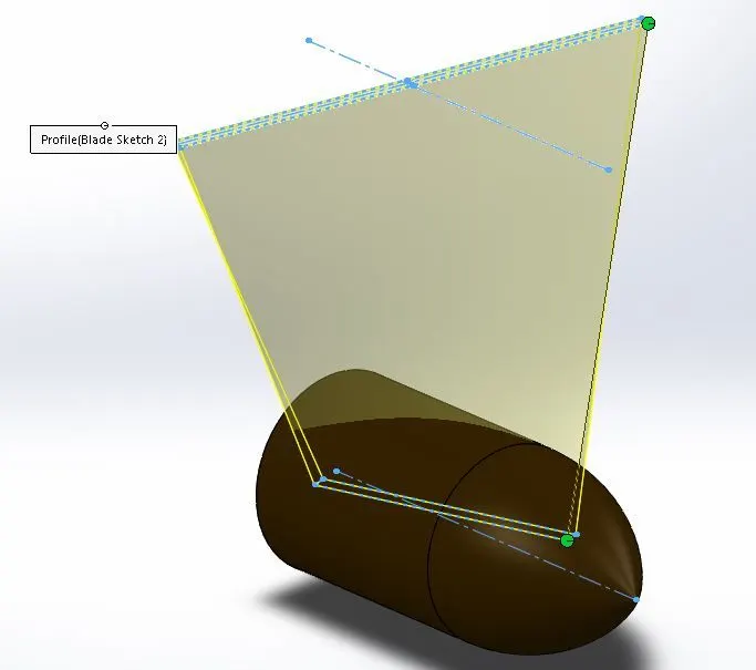
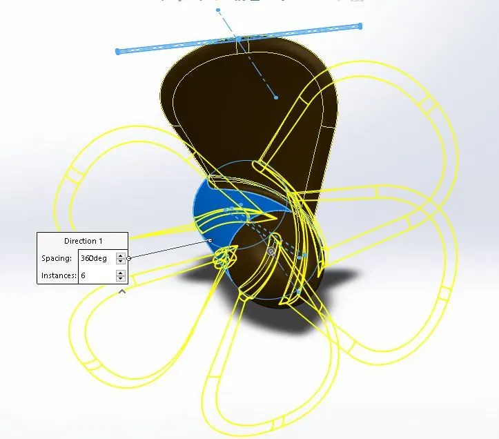
- The following features are used to model this propeller - revolved boss, lofted boss, fillet, and circular pattern.
- First, a fully-defined sketch of the propeller hub is created on the right plane, and then using the revolved boss feature the solid model is created.
- The lofted boss feature is used to create the propeller blades.
- Fillets are provided on the blades to decrease hydrodynamic losses and improve blade efficiency.
- A hole is cut in the hub using an extruded cut feature to connect the propeller with the engine shaft
- Custom color appearance is given to the propeller.
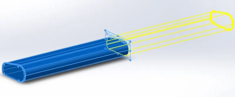
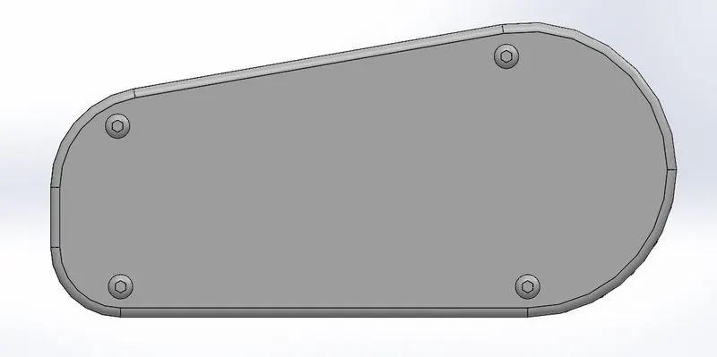
B. Radar
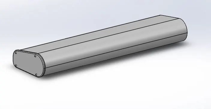
Radar is installed at the top of the yacht/any ships to determine the presence of any ships/detect any nearby target over a considerable distance using radio waves.
Procedures and features used:
- The following features are used to model this propeller - extruded boss, extruded cut, fillet, mirror, and split line.
- The radar model is symmetric about its mid-plane, so, the half model is created and then mirrored to get a complete radar model.
- The entire radar body is created using the extrude boss feature and then mirrored. Various holes are cut at required positions using the extrude cut feature.
- Fillets are provided at sharp edges.
- A text is created on the radar using the split line feature.
C. Hull
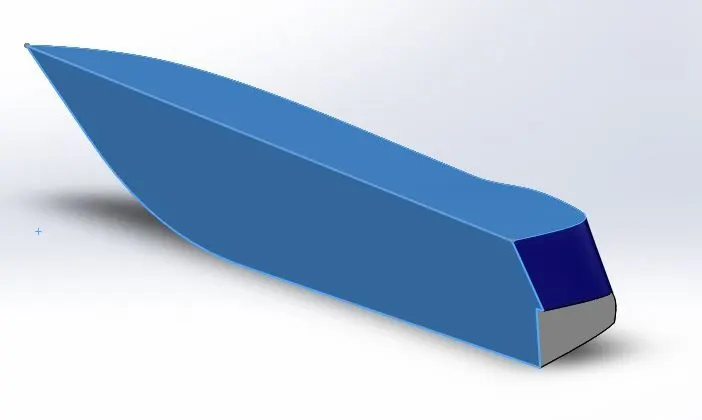
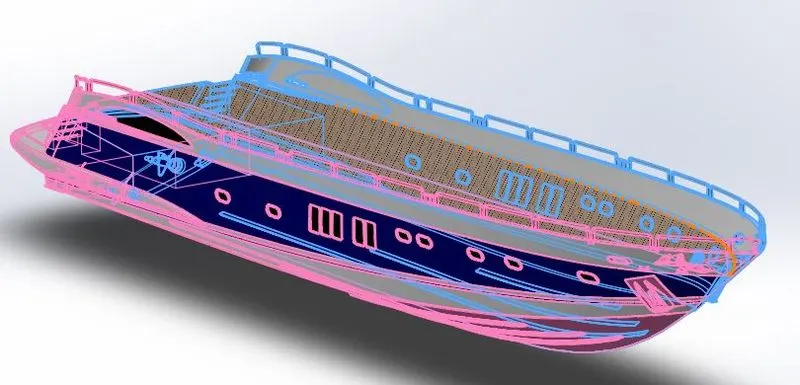
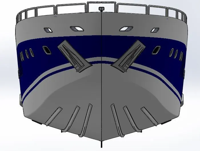
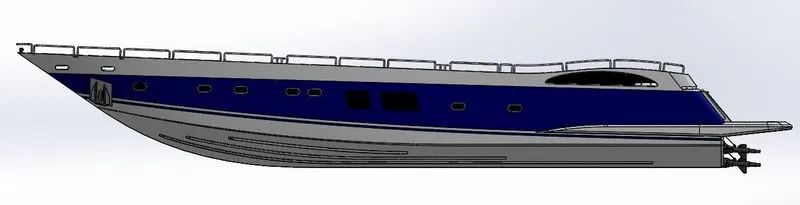
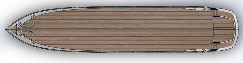
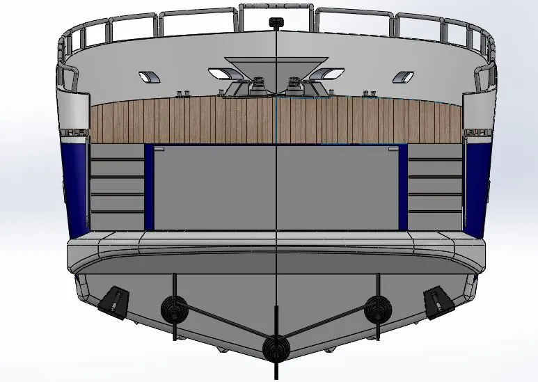
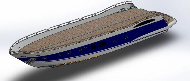
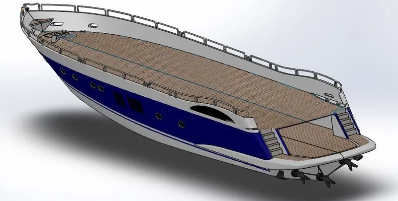
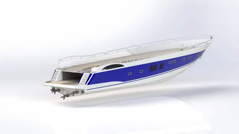
Hull is the main body/framework of the yacht on which all other components are fixed.
Procedures and features used:
- Features used while modeling the hull of the yacht are lofted surface, extruded boss, extruded surface, surface offset, extruded cut, revolved boss, fillet, split line, split, chamfer, sweep boss, surface knit.
- First, the blueprints of all the views are placed in the environment. Using these blueprint as a reference create the surface bodies of the hull.
- Then using the knit-surface feature, convert the surface bodies into solid objects. Once the solid model is formed all other hull features are created using extruded boss, extruded cut, revolved boss, and sweep boss.
- Ropes for anchors are created using helix and sweep features.
- Railings and the curved surfaces of the hull are created using the projected curve option. The split line option is used to create a split appearance on the outer surface of the hull.
- The garage space is created using the split option. The body consumed while creating the garage space is saved as a garage door.
- A surface is created using the offset surface feature by keeping the offset distance as zero. This surface appears to be hidden on the deck of the hull. This surface is used as a reference for seat modeling.
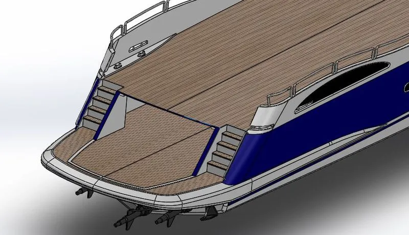
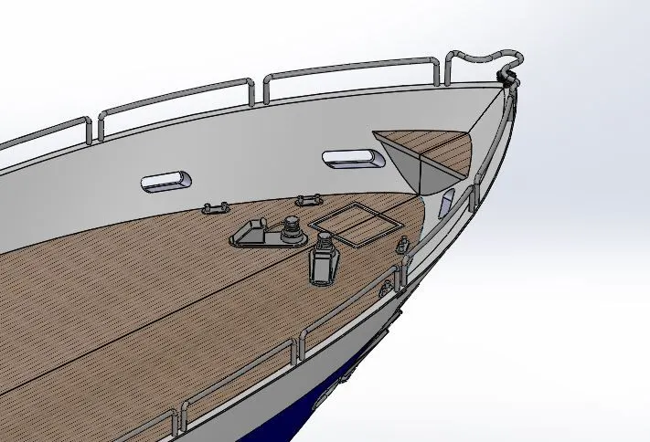
- Decals are used on the deck of the hull, stairs, and on the floor of the garage space.
D. Garage Door
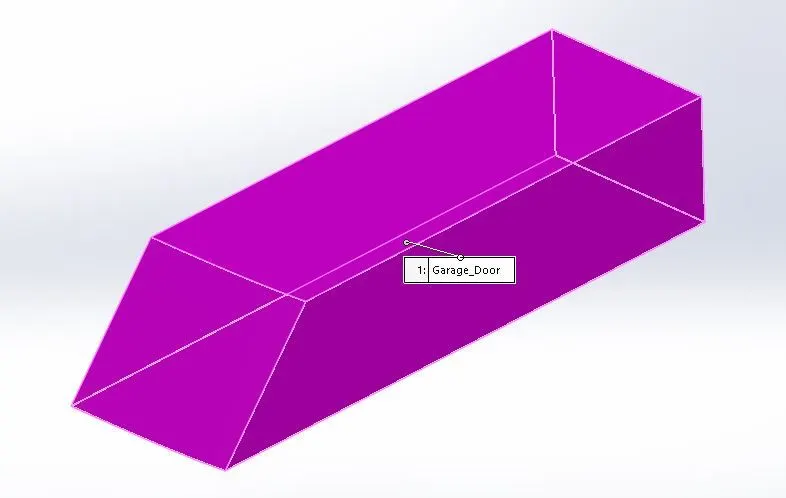
An openable door for the garage where all the vehicles will be parked.
Procedures and features used:
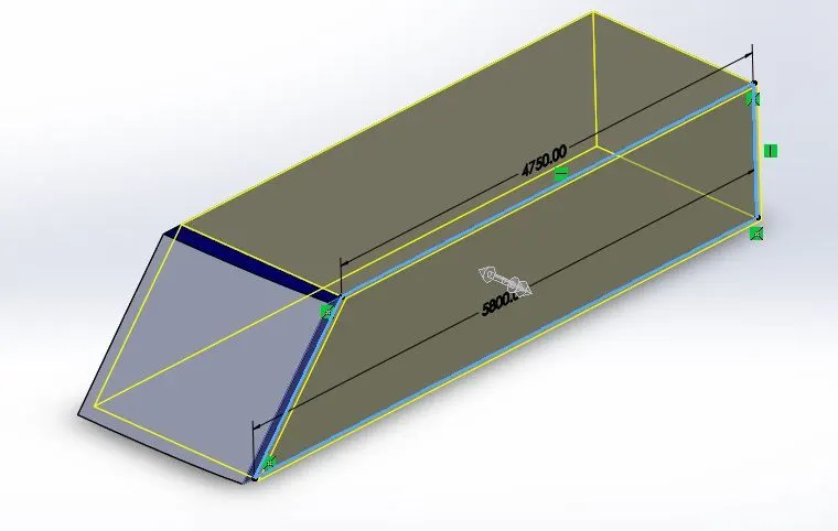
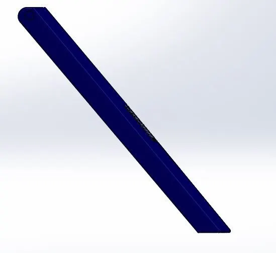
- The following features are used to create a garage door - extruded cut, fillet, shell, mirror.
- This part of the hull is consumed using a split feature which is used to create a garage door. First, the unnecessary part of the garage door is removed using an extrude cut feature, and then it's made hollow using a shell feature.
- As the door is symmetric about the midplane, we will create half portion of the door and then the other half will be mirrored. Fillets are provided at all the required edges.
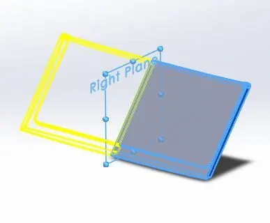
- A text is created on a separate plane and then projected on the garage door with the help of extrude cut feature.
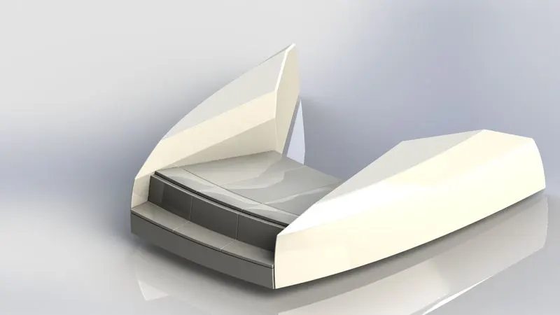
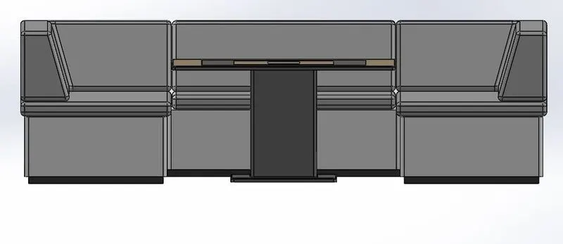
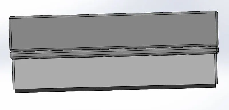
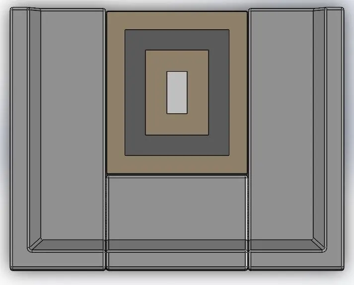
E. Front Seat, Middle Seat, and Rear Seat
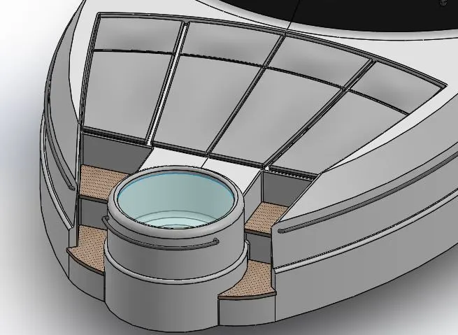
These seating arrangements are located at the front, middle, and rear end of the yacht respectively.
Procedures and features used:
- Features used while modeling the seats are extruded surface, surface sweep, lofted surface, boss extrude, extruded cut, ruled surface, revolve boss, and fillet.
- First, the insert part option is used and only the surface bodies of the hull part are inserted for reference.
- All the surfaces are created with the help of blueprints. The seats are symmetric about mid-plane so half the part will be created by surface modeling and other features, and the other half will be mirrored. The model will be converted into solid bodies using a knit surface.
- To create pillows offset and revolve boss feature is used. The Dome feature is used to give a curvature effect to the pillows.
- The flag on the rear seat is created using the revolve boss feature, and lofted surface feature.
- Fillets are provided at all necessary edges.
FRONT SEAT
MIDDLE SEAT
REAR SEAT
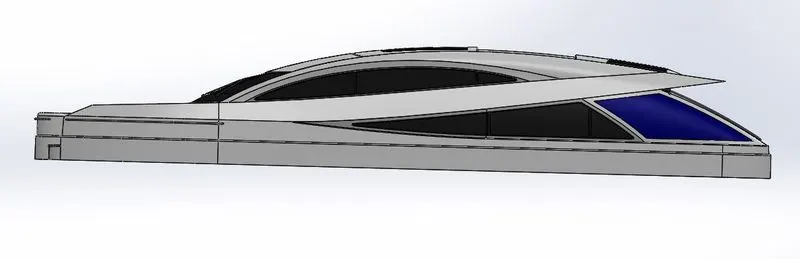
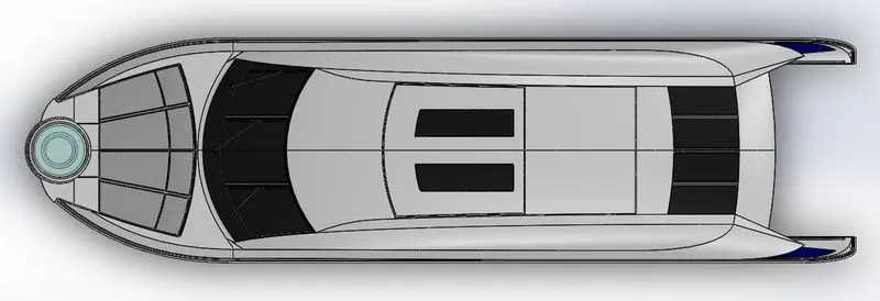
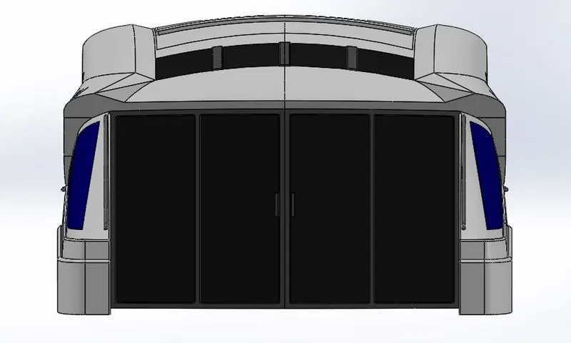
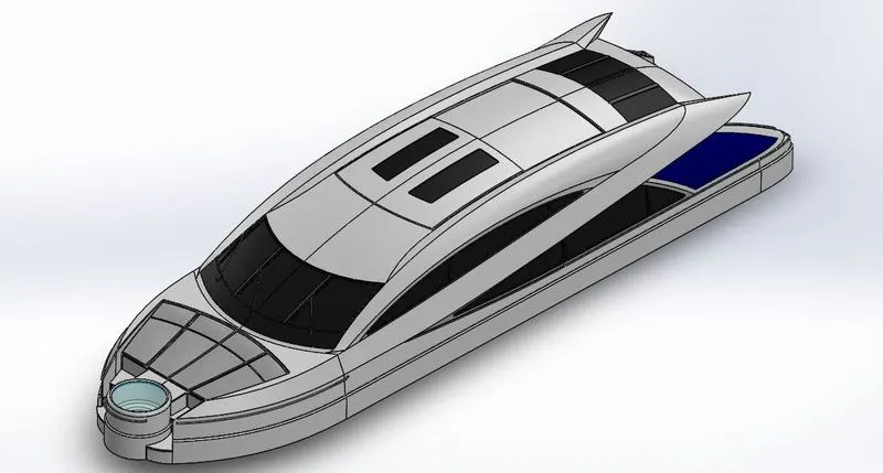
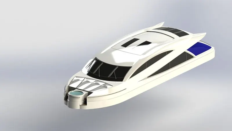
F. Superstructure
A superstructure is a unit assembled on the deck surface of the hull which consists of a control system, radar mast unit, and other amenities.
Procedures and features used:
- The superstructure is modelled in a similar way as we did while modelling the hull i.e generating surface bodies with reference to the blueprint.
- First, the hull surface(i.e deck surface) is imported that forms the base for creating the superstructure of the yacht.
- Features used for modeling are surface extrude, extend surface, lofted surface, knit surface, offset surface, filled surface, trim surface. Projected curves are developed for creating surface bodies.
- One section of the model is created and the remaining section will be mirrored about its midplane. The final surface body will be converted into a solid body. Other detailing will be done using the boss extrude and extrude cut feature.
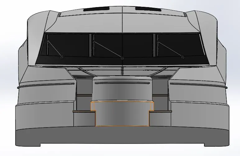
- Lastly, a surface is created using the offset surface feature with zero offset distance at the top of the superstructure. This surface is used as a reference for creating a radar mast.
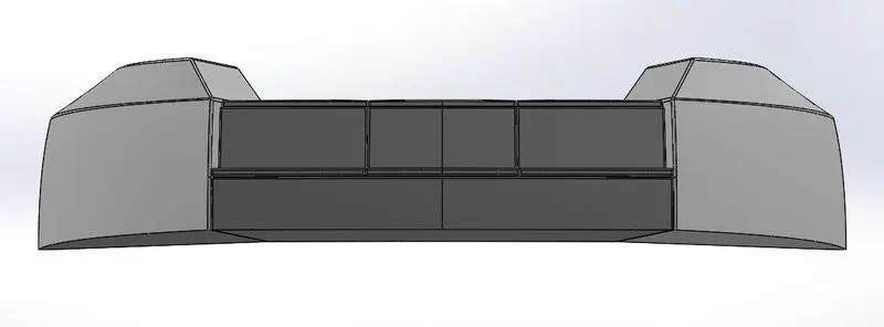
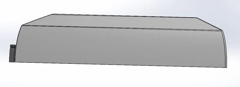
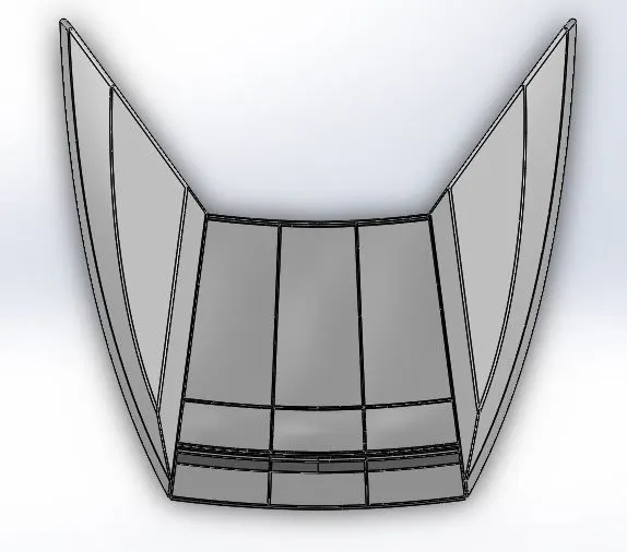
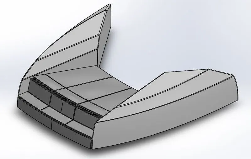
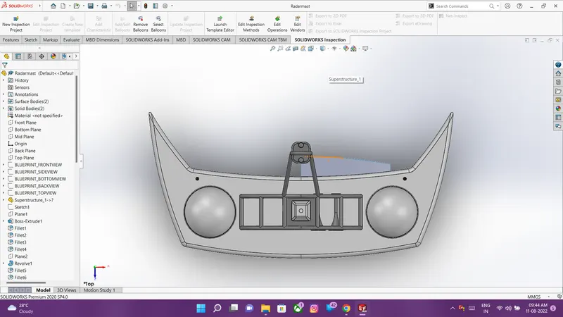
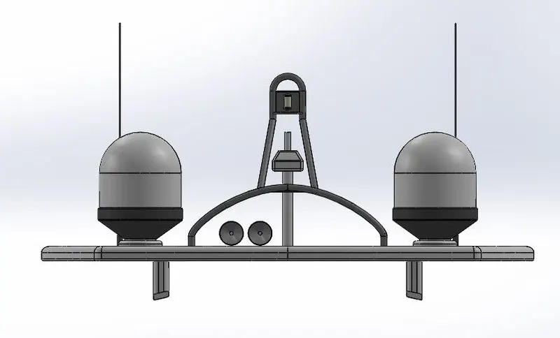
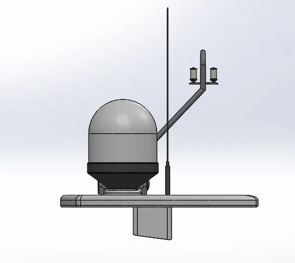
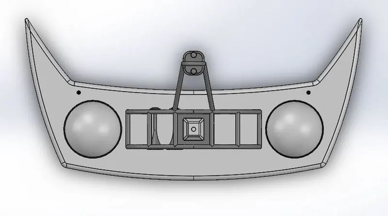
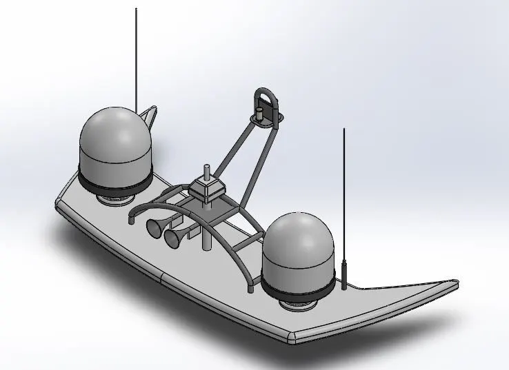
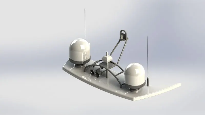
G. Radar Mast
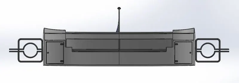
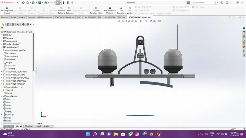
The radar mast is assembled on top of the superstructure on which the radar is fitted. It contains a receiver/antenna which collects the signal and triggers the radar to move.
Procedures and features used:
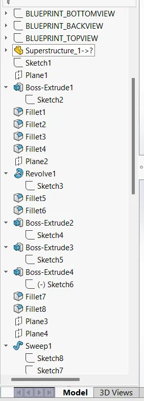
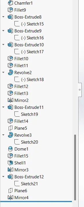
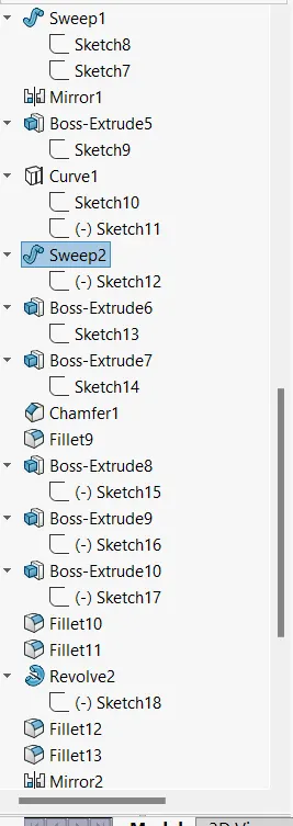
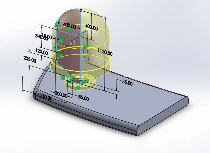
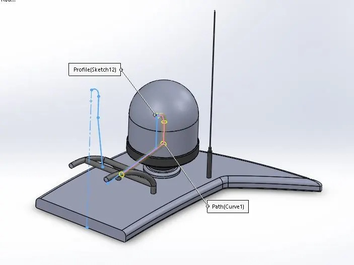
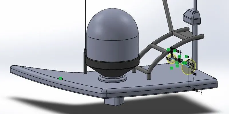
- First, import the surface body created in the superstructure which will be used as a reference. Features like boss extrude, cut extrude, revolve boss, swept boss, projected curve are used to model radar mast.
- Projected curves are used to create pipe bodies using the swept boss feature. Dome feature is used to form curvature on the horn surface. Shell feature is used to get hollow horn body.
- Chamfers and fillets are provided at the required edges.
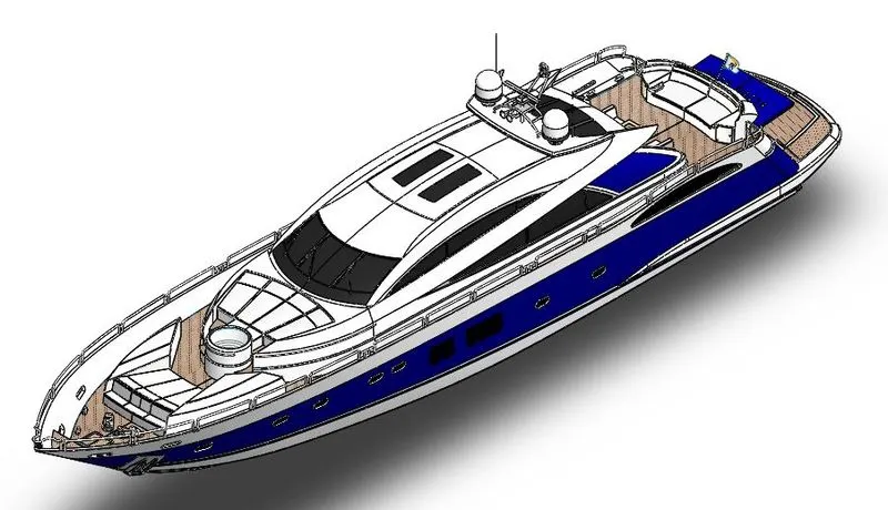
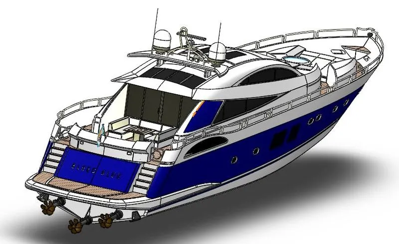
Yacht Assembly
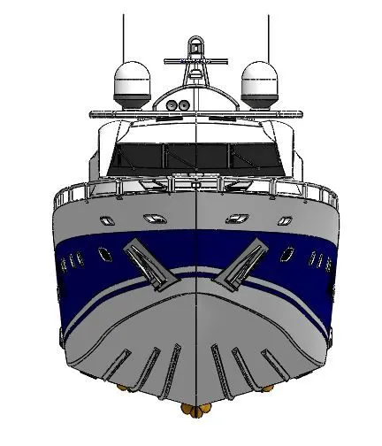
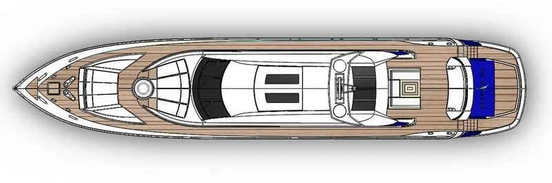
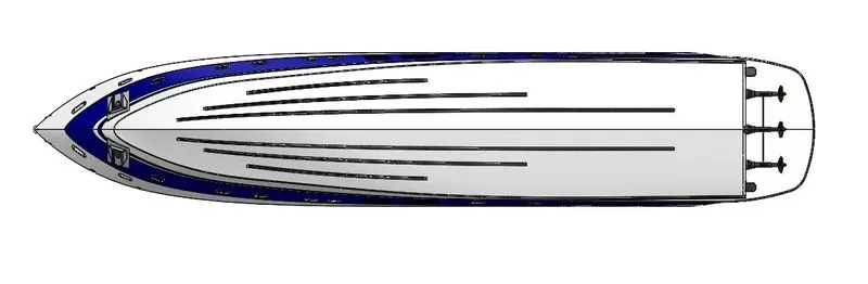
- First, a new assembly file is created and the hull component is inserted into it which will be automatically fixed. All the other parts will be mated with reference to the hull of the yacht.
- Various mates like concentric, coincident, parallel, distance, width, etc are used with respect to faces, planes, edges, points.
Adding Decals and Setting up scenes
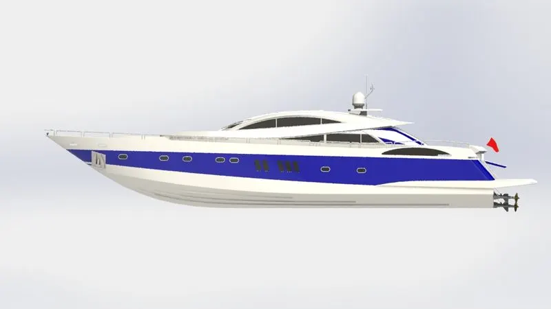
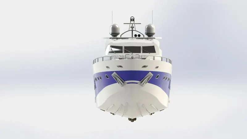
- Decals are graphic art printed on any components for an aesthetic look. Below images represent the decal added to the hull, superstructure, and the flag on the rear seat.
- For setting up scenes, various pre-installed scenes can be used which are available in the SolidWorks library. You can adjust the environment, camera view, brightness, shadows in the edit scene option.
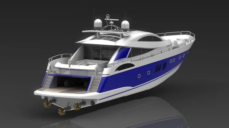
- You can also add multiple lights such as spotlight, direction light, etc to get a perfectly rendered image. The below image shows the yacht rendered in a dark scene with light.
Detailed Rendering of Predator Yacht
- Rendering is used to create photorealistic images of the model placed in an actual suitable environment associated with different features.
- Rendering is done using various software and tools. We have used SolidWorks photoview360 and SolidWorks Visualize.
Conclusion:
- While creating solid models of complex geometries of predator yacht I have learned about various surface/solid modeling features that simplify the process to develop a CAD model.
- Understanding the assembly methods using different mates like simple, advanced, and mechanical mates.
- Understanding how to create photorealistic images using environment, scene setup, camera, lights, etc in SolidWorks photoview360 and SolidWorks Visualize.
- SUNSEEKER PREDATOR YACHT