Radar Mast & Final Assembly of Yacht
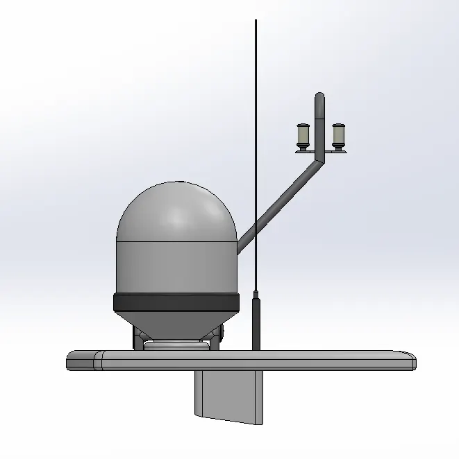
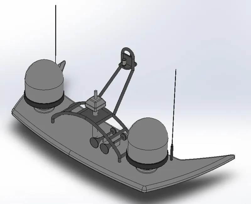
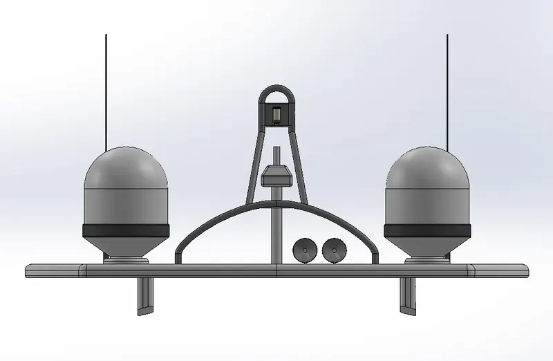
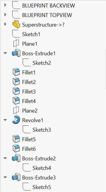
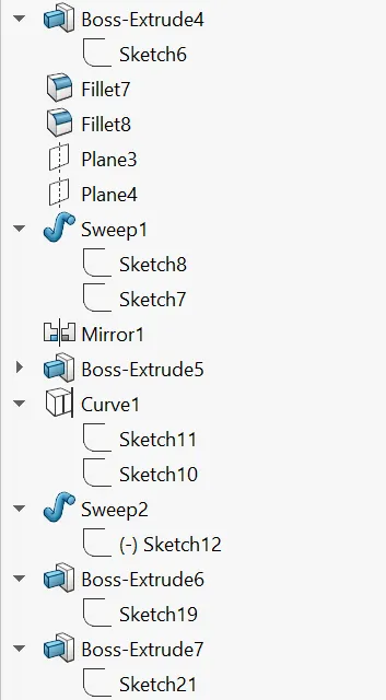
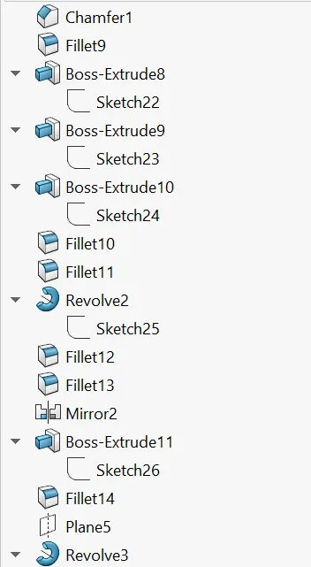
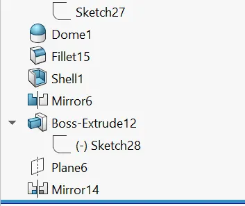
1.Radar Mast :
2.Assembly Yacht :
Design,Assembly and Rendering of an Predator Yacht
Objective :
- To Design individual parts of the yacht with fully defined sketches and appropriate appearances.
- To Assemble all the individual parts of the yacht by assembling with suitable mate relations.
- To Render the yacht model by adding appearances,decals,lights,cameras and background scenes.
Introduction :
Predator yacht - A Yacht is a watercraft used for pleasure or sports.It is originally referenced light,fast sailing vessels that the dutch republic navy used to pursue pirates and transgressors around into the shallow waters of the low countries.The yacht was popularized by charles II England as a pleasure or recreation vessel following his restoration in 1660.
Nowadays yachts are almost exclusive for leisure. A yacht is any sail or power vessel used for pleasure,cruising or racing.The world often needs luxury;nor is it always desirable.Many racing yachts are stripped-out vessels with a minimum of accomodations to lower weight.The word 'sailboat'or'sail yacht' is used in america to differentiate from 'power boat'or'power yacht'.
Design Methodology :
Flowchart :
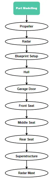
Design Process :
The entire modelling process is devided into six stages,
- Blue Print Setup and Creating Planes.
- Modelling of Hull Part.
- Modelling of Superstructure.
- Modelling of Radar Mast.
- Modelling Front,Middle,and Rear Seats.
- Assembling the individual parts.
Commands Used :
Sketch :Create the sketches and decide how to dimension and where to apply relations.
- 2D Sketch :
Creating a model usually begins with sketch.From the sketch,we create features to make a part.Then we can combine and mate the appropriate parts to create an assembly.From the parts or assemblies,we create drawings.
- 3D Sketch :
When sketching in 3D,we can snap to the major directions X,Y,orZ and onstrains are applied along X,Y,Z respectively.These are constrains to the global coordinate system.When sketching on a plane,we can snap to horizontal or vertical directions in the plane,and constrains are applied to the horizontal and vertical planes.These are constrains to the plane,planar face,etc..,
- Sketch Commands :
1. Smart Dimention - Creates a dimension for the selected sketch entity.
2. Line - Line is one of the first sketching tools in solidworks sketch command manager which can be drawn horizontally,vertically or at any angle.It plays very important role to complte the 2D drawing of the product or part and very easy to utilize its features.
3. Circle - The circle is another important sketching tool which enables to create the circular drawings on the graphics area.There are two circle tools are available and they are "Centre circle" and "Perimeter circle".
4. Rectangle - It sketches Rectangle or square with a center point at a selected angle.Parallelogram sketches a standard parallelogram.
5. Spline - A two or three dimentional curve defined by aset of control points.Points within a spline can be added or deleted.
6. Point - Inserts a point or vertex into a sketch entity.This cannot be deleted if it is apart of sketch endpoint or center point.
7. Offset Entities - Copy a sketch entity to a specified distance from the original entity.Must have a sketch entity already drawn and selected to use this tool.
8. Convert Entities - Convert entities enables you to copy model edges into your active sketch.These sketch elements are automatically fully defines and constrained with an edge relation.Convert entities is like offset entities expect that the offset distance is always zero.
9. Sketch Picture - It is used to insert an image file into the background of a sketch for a reference.This allows the user to make 2D sketches based on the image.Use the sketch picture property manager to alter the inserted image.
Features :Select the appropriate features,such as extrudes and fillets determine the best features to apply for the sketch and in what order to apply those features must be decided.Some sketch based features are shapes such as bosses,cuts,and holes other sketch based features such as lofts and sweeps use a profile along a path.Another feature is called an applied feature,which does not require a sketch.Applied features include fillets,chamfer,or shell.They are called 'applied' because they are used in existing geometry using dimentions and other charectristics to create the feature.Typically,we create parts by including sketch based features such as bosses and holes.It is possible to create a part without sketch based features.
Feature Commands :
1. Extruded Boss/Base - One of the oldest commands in the SOLIDWORKS software is the extruded boss/base command.An Extruded Boss/Base feature will allow us to take a 2D sketch and add thickness to it in the third dimension.
2. Extruded Cut - It's a tool to remove material by projecting asketch section normal to the sketching plane.
3. Split - Lines are used to devide model faces into two.Spline lines are created like any other sketches feature.They can be one or more connected sketch entities.They must be oriented so that they will pass through model faces when projected normal to the sketch plane.
4. Dome - It can add one or more domes to the selected planar or non-planar faces.The software calculates the distance using the radius of the arc as a basis for the dome.
5. Project Curve - Select bi-directional to create a projection that extends on both sides of the sketch.The curve can be used as a path for a sweep.
6. Composite Curve - We can create composite curves by combining curvessketch geometry,and model edges into a single curve.Composite curve can be used as a guide curve when creating a loft or a sweep.
Surfaces :Surfaces are a type of geometry that can be used to create surface features with zero thickness.This zero thickness geometry is known as surface.The surfaces are generally used to create models of complex shapes.We can convert surface models in solid models.We can also extract a surface form into solid model using the tools available for surface modeling.
Surface Commands :
1. Lofted Surface - Creates a lofted surface between two or more profiles or sketches.Specify start and end constrains and add guide curves to control the path shape.
2. Boundary Surface - The boundary surface feature lets us to create surfaces that can be tangent or curvature contineous in both directions.In most cases,this delivers a higher quality result than the loft tool.
3. Extruded Surface - Extrudes a sketch or selected sketch contours in one or two directions to create a surface extrude feature.
4. Revolved Surface - Revolves a sketch or selected sketch contours around an selected axix to create a revolve surface.
5. Swept Surface - It sweeps a closed profile along an open or closed path to create a surface feature.It uses a tangent plane at the end of the path so that the path is normal to the swept surface.
6. Filled Surface - Patches a surface within a boundary defined by edges,sketches,or curves to fill surfaces and adjust resolution control to improve surface finish.
7. Ruled Surface - Inserts ruled surface in a specified direction from edges.Tangent to surface,Normal to surface,tapered to vector,perpendicular to vector or sweep can be selected.We can also trim and knit the surface and remove any connecting surfaces.
8. Trim Surface - It trims the surface where a surface intersect with another surface,a plane or a sketch.
9. Knit Surface - It combines two or more adjacent,non-intersecting surfaces into a single surface body.The surfaces must join at an edge.if the resulting knit surface encloses a volume,we can create a solid body from the property manager.
10. Extend Surface - Extends one or more edges or faces on a surface,based on end conditions and extnsion type.
11.Mirror Surface - A mirror feature is a copy of selected feature,mirrored about a plane or planar face.A mirror sketch entity is a copy of a selected sketch entity that is mirrored about a centerline.if the original feature or sketch is modified,the mirrored copy is updated to reflect the change.
Description :
1.Blueprint Setup :
Blueprint is basically adesign plan or technical drawings of different orthographic views of a product.The main motto of the blueprint is to bring out the exact same shape and form of the product as designed by a designer. it also ensures the accuracy and proportion of the product.Designing a product without a blueprint may lead to multiple errors and improper dimentions.A proper blueprint ommits this kind of problems.
To set up a blueprint,we use sketch mode in SOLIDWORKS in each plane.in case,the images provided for the front viewside view,top view,back view,and top views are added in respective planes.Very important thing to note while setting up the blueprint is the size of it.As all parts are going to be designed laying up the blueprint and taking its reference,it is very crucial to maintain the correct and real size of blueprint in the very first step.It can either adjusted manually with the dimentions or by adjusting the scale bar.
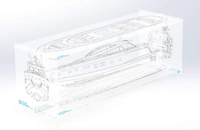
Methodology :
- Select a plane & select a 2D drawing option & go to tools-sketch-picture.
- Browse the image & change the dimentions as per requirements & use transparancy for convenient sketching & name the views.
- Repeat the above steps and name it as Front view,side view,Top view,Back view.
- Change the name of the planes as front plane,bottom plane & mid plane and arrage the blueprints in a sequential order.
2.Hull :
A hull is the watertight body of a ship or boat.The hull may open at the top or it may be fully or partially covered with a deck.The line where the hull meets the water surface is called the waterline.
The hull of a ship is the most notable structural entity of the ship.To define the hull,it can be said that it is the watertight enclosure of the ship,which protect the cargo,machinary,and accomodation spaces of the ship from the weather,flooding,and structural damage.
Before Render :
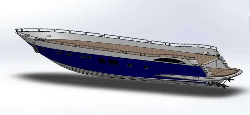
Commands Used :
- In Sketch : Line , Spline , Circle , Rectangle , Arc , Slot , 3D Sketch , Sketch Picture.
- In Surface : Extrude Surface , Revolved Surface , Lofted Surface , Surface Trim , Surface Fill , Surface Knit , Delete Face.
- In Feature : Project Curve , Chamfer , Fillet , Reference Plane , Split , Split Line , Extruded Boss/Base , Extruded Cut , Mirror.
After Render :
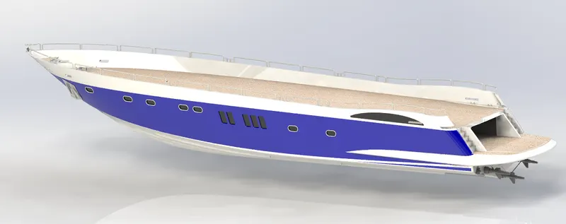
3.Superstructure :
A superstructure is an extended construction of any building or platform that rises above the rest of the building or platform in a distinct manner.The word comes from a combination of two latin words,the latin word 'super' means in addition or above or in excess of,wheres the stem word 'structure' means to build or to heap up.Thus,superstructure to add a constructuion to already existing structure.However any mast, sails,any arsenal are not included in this category.
The size of a superstructure has a great influence on the mobility of the vessels.They are designed in a manner,so that they add value and hinder the speed and mobility in the least.The superstructure is mostly designed in fashion as well.This is because it is the most easily visible part of the ship,ans so the designers try to provide it with the identity that is unique.
Before Render :
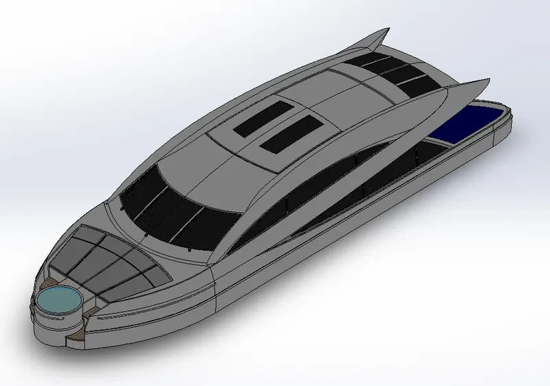
Commands Used :
- In Sketch : Sketch Picture , 3D Sketch, Line , Spline , Circle , Rectangle , Center Point Arc.
- In Surface : Extruded Surface , Swept Surface , Ruled Surface ,Knit Surface , Trim , Surface , Extend Surface , Filled Surface , Lofted Surface , Revolved Surface , Fillet , Chamfer.
- In Feature : Project Curve , Reference Curve , Convert Entities , Split , Split Line.
After Render :
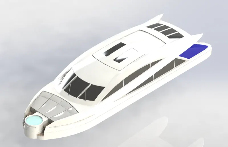
4.Radar Mast :
A mast is a vertical ship structure mounted on top of bridge and forward of the forecaste towards the ship's bow.It accounts for the support platform for the ships derrick and hold necessary equipements such as radars,navigation light and ships horn in case of foremast.They are made of high tensile steel with added rigidity based on the size of derricks it holds.Other than that a ships main mast is also used to hoist ships flag.
Out of different parts of ship the main job of mast is to hold necessary equipment such as radar receiver,navigation lights,ships horn,flags and derricks in some case.
Before Render :
Commands Used :
- In Sketch : Sketch Picture , Line , Spline , Rectangle , Arcs.
- In Feature : Extruded Boss/Base , Lofted Boss/Base , Revolved Boss/Base , Swept Boss/Base , Reference Plane , Project Curve , Fillet , Mirror , Dome , Shell.
After Render :
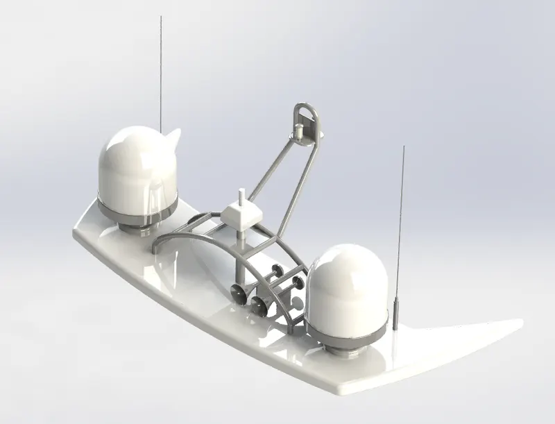
5.Rear Seat :
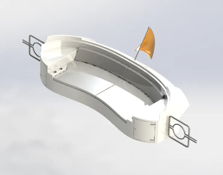
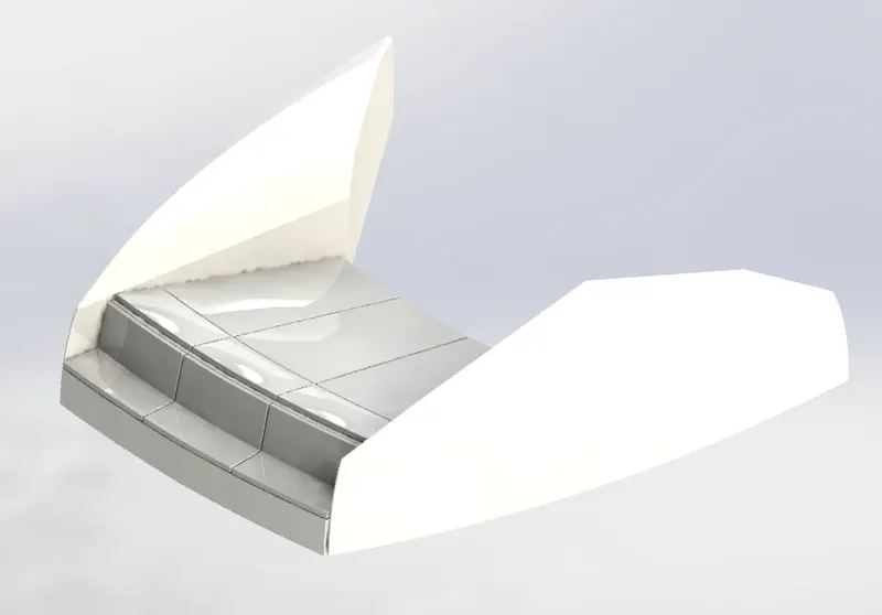
A seat is a place to sit.The tearm may encompass additional features,such as back,armrest,head restraint but also headquarters in a wider sense.It may also comes under luxuries,materials uses for the seat etc. here,this seat position on back side of the yacht.
It is placed at the backend of the hull,It can accomodate 3persons and gives a perfect of the backside of the ocean view.
It is also designed with reference to the deck surface as the ground and the blueprint sketches as the reference for the dimentions and views.Surface features are employed more in this seat than in the others.it is also provided with a flag at the end which is designed as asurface to represent the natural looks if a flag in wind.It lies at the back of the middle table and the end of the deck surface.
Before Render :
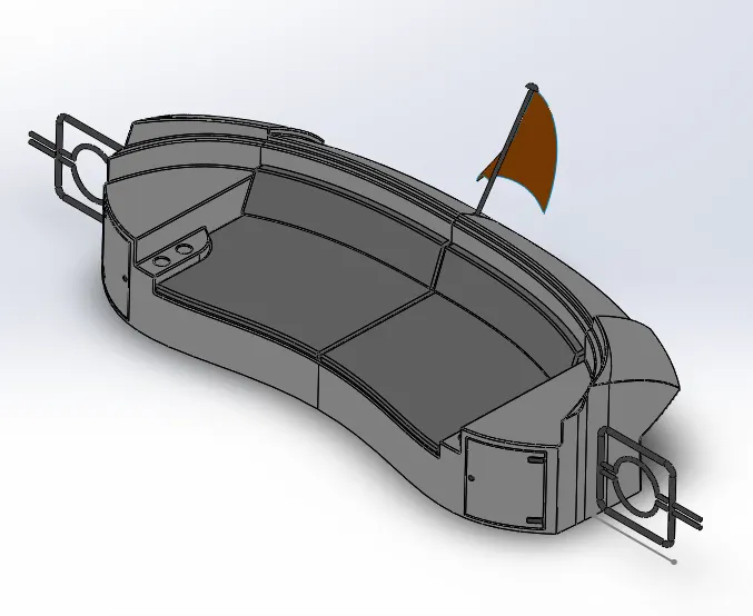
Commands Used :
- In Sketch : Sketch Picture , Line , Spline , Circle , Arcs , Rectangle.
- In Surface : Swept Surface , Extruded Surface , Off-set Surface , Filled Surface , Knit Surface , Ruled Surface , Lofted Surface.
- In Feature : Reference Plane , Extruded Boss/Base , Revolved Boss/Base , Fillet , Mirror.
After Render :
6.Middle Seat :
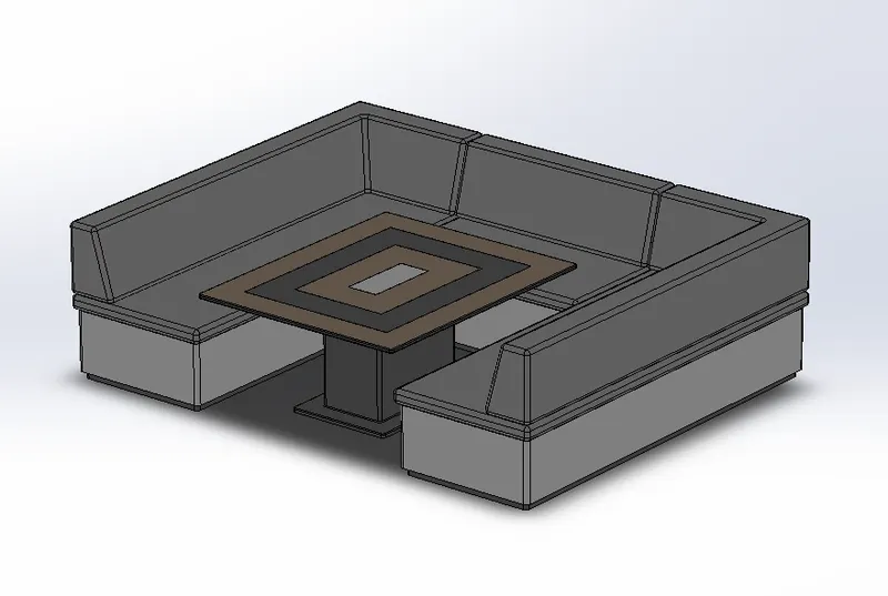
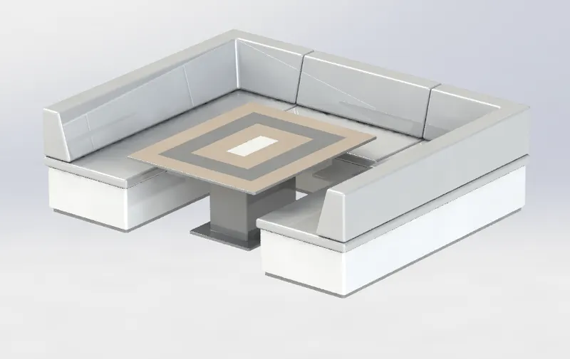
The middle seats are designed to accomodate more than the rear seat,It can accomodate upto 6 people at a time and atable is provided in the centre to have foods or to party.This is located between superstructure and rear seat.A seat is a place to sit.The tearm may encompass additional features,such as back,arm and head restraints.It is also designed with reference to the deck surface as the ground and the blueprint sketches as the reference for the dimentions and views.This seat is in u shaped witha table in middle.It lies behind the superstructure of the yacht.this part design was done without involving surface design.It may also comes under luxuries,materials uses for the seat etc.
Before render :
Commands Used :
- In Sketch : Sketch Picture , Line , Rectangle.
- In Feature : Extruded Boss/Base , Chamfer , Fillet , Mirror , Reference Plane.
After Render :
7.Front Seat :
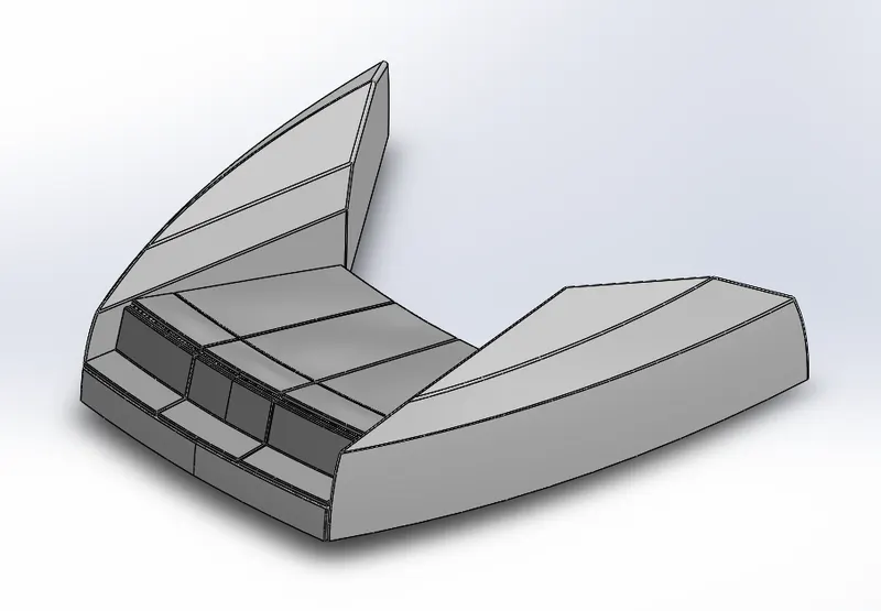
A seat is a place to sit.The term may encompass additional features,such as back,arm,and head restraint but also headquarters in a wider sence.It is designed with reference to the deck surface and the blueprints.It is designed using surface features and also extruded features.Domes are applied to the surfaces to imitate the cuisions of the seat.
A small water pool in the superstructure behind the front seat.It may also comes under luxuries,materials uses for the seats etc.This seat positioned on front side of the yacht.The front seat is designed to have a nice and wider view of the ocean.
Before Render :
Commands Used :
- In Sketch : Sketch Picture , Line , Spline , Circle , Arcs.
- In Surface : Extruded Surface , Lofted Surface , Trim Surface , Filled Surface , Filled Surface , Knit Surface , Swept Surface , Revolved Surface.
- In Feature : Extruded Cut , Revolved Boss/Base , Chamfer , Fillet , Mirror , Dome.
After Render :
8.Radar :
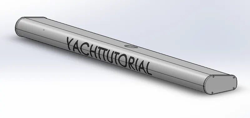
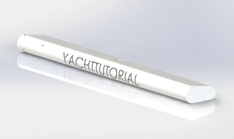
Marine radars are X band or S band radars on ship,used to detect other ships and load obstaclesto provide bearing and distance for collision avoidance and navigation at sea.They are electronic navigation instruments that use a rotating antenna at sweep anarrow beam of surrounding the ship to the horizon,detecting targets by microwaves reflected from them,generating apicture of the ship's surroundings on a display screen.
Before Render :
Commands Used :
- In Sketch : Line , Text , Circle , Point.
- In Feature : Extruded Boss/Base , Extrude Cut , Sketch Pattern , Fillet , Mirror , Split Line.
After Render :
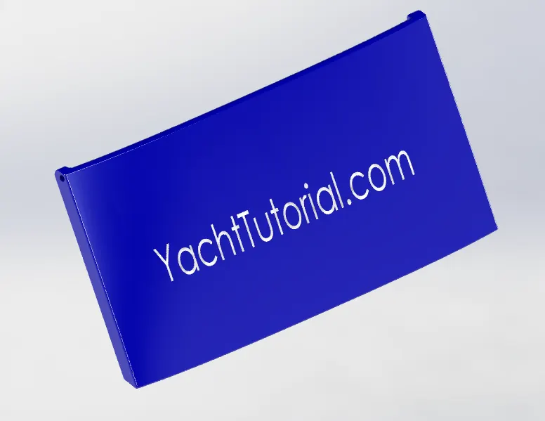
9.Garage Door :
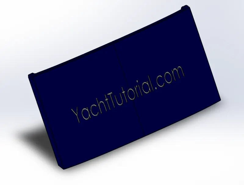
It's a door for the garage.A garage door is a large door on a garage that opens either manually or by an electric motor.Garage doors are frequently large enough to accomodate automobiles and other vehicles.Small garage doors may be made in a single panel that tilts up and back across the garage ceiling.
It was created out of the splited block from the hull.It is provided with two holes at adjust the pins in order to open and close the garage door.
Before Render :
Commands Used :
- In Sketch : Line , Spline , Circle , Text.
- In Feature : Extruded Cut , Reference Plane , Fillet , Shell , Mirror.
After Render :
10.Propeller :
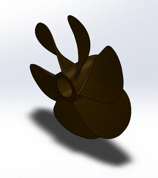
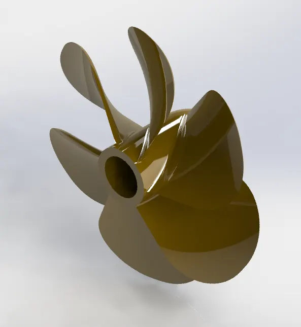
A propeller is adevice with a rotating hub and radiating blades that are set at a pitch to form a helical spiral,that when rotated,performs an action which is smilar to archimedes'screw.It transforms rotational poer into linear thrust by acting upon a working fluis,such as water of air.
The rotational motion of the blades is converted into thrust by creating a pressure difference between the two surface.A given mass of working fluid is accelerated in one direction and the craft moves in the opposite direction.propeller dynamics,like those of aircraft wings,can be modelled by bernoulli's principle and newton's third law.Most marine propellers are screw propellers with helical blades rotating on a propeller shaft with an aproximately horizontal axis.
The sketch profiles are created with provided dimentions and the features are applied.There are three instences of the propeller at the bottom of the yacht.
Before Render :
Commands Used :
- In Sketch : Spline , Circle , Line.
- In Feature : Revolved Boss/Base , Lofted Surface , Extrude Cut , Reference Plane , Circular Pattern , Fillet.
After Render :
Assembly of Predator Yacht :
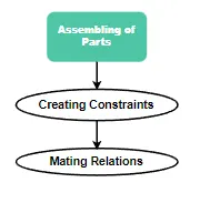
An assembly is a document in which parts,features,and other assemblies are mated together.The documents separate from the assembly.For example,in an assembly,a piston can be mated to other parts,such as a connecting rod or cylinder.This new assembly can then be used as a sub assembly of an engine.The extension for a SolidWorks assembly file name is SLDASM.
Before Render :
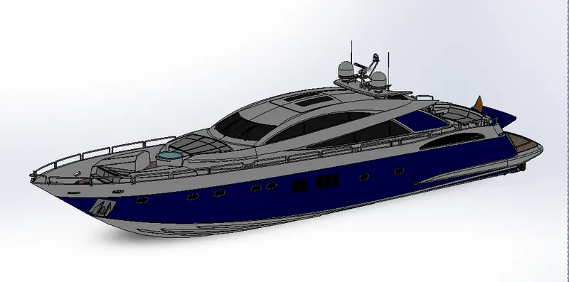
Assembly Commands :
- Smart Mate : A smart mate is an assembly mating relation that is created automatically.
- Mate : A mate is ageometric relationship,such as coincident,perpendicular,tangent, and so on between parts in an assembly.
- Mate Group : A mate group ia a collection of mates that are solved together.The order in which the mates appear whithin the mate group does not matter.
- Sub-Assembly : A sub-assembly is an assembly document that is part of a large assembly.For example, steering mechanism of a car is a sub-assembly of the car.
- Insert Components : We can insert multiple instances of the group of components without closing the property manager.
After Render :
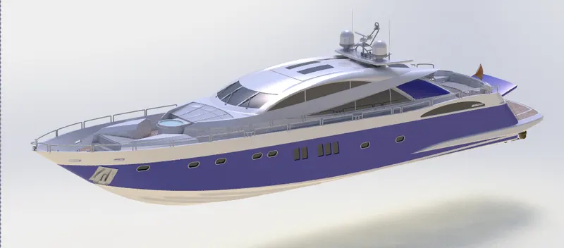
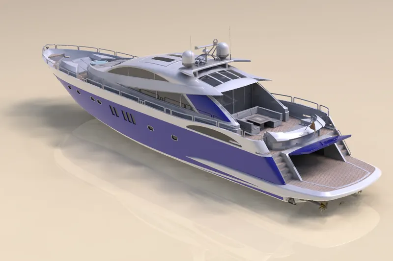
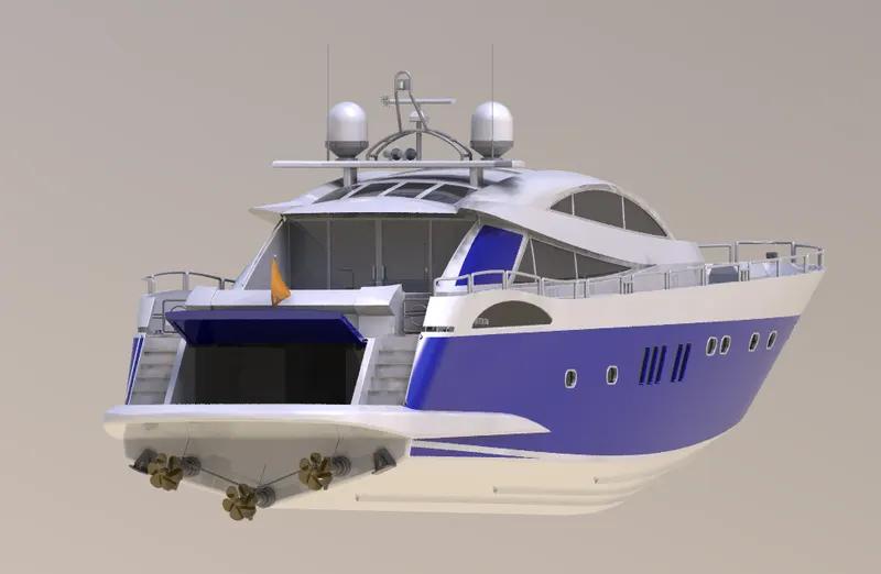
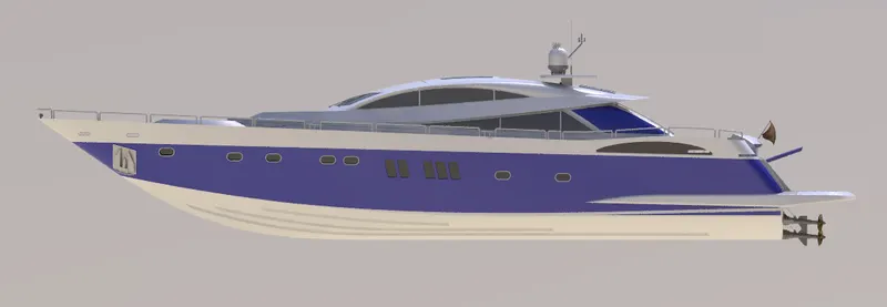
Render of Predator Yacht : (Photoview 360)
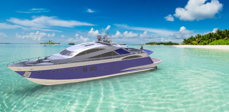
Photoview 360 is a visualization and rendering solution included with SOLIDWORKS.Providing a highly interactive environment for viewing designs as well as for creating photo-realistic renderings.It can be used to showcase our designs.
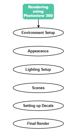
It is a software package,separate to solidworks which generates digital lifelike images from solidwork files.Photoview 360 is an easy and quick way to produce high quality photorealistic images.
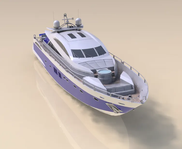

Render with Background using Photoview 360 :
Conclusion :
-The parts of the Yacht are sketched as per the dimensions using solidworks.
-The Sketches are Modelled with required state.
-All the parts are inserted in the Assembly section and assembled the yacht with mating relations.
-The lighting,camera setup are given using Photoview 360.
-The Realistic image was rendered with the use of Photoview 360.