Radar Mast & Final Assembly of Yacht
Design, Assembly and Photo-Realistic Rendering of an American Predator Yacht
Objective:
The objective of the project is to design and model all the parts of an American Predator Yacht and assembling it to create the Photo-Realistic rendering of the yacht.
Introduction:
In this project I have created an american predator yacht from scratch using Solidworks 2019. I’ve done the rendering of the final model in Photoview 360. Each and every part of the yacht was designed and modelled using SOLIDWORKS. Then the modelled parts were assembled by adding proper mates and constraints to create the Photo-Realistic rendered image of the Yacht.
Various features have been used including features of surface modelling and solid modelling. In this project each and every feature is explained in detail and the images of all the parts, assembly and photos of rendered yacht are attached.
First the design methodology has been explained with the help of flowchart. Then description of each tool and feature is provided along with the images of parts. Then the images of assembly has been attached and various mates are explained. In the end, the rendered images are attached.
Design Methodology:
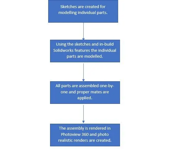
Bottom-up assembly modelling is used in this project. First, the individual parts are modelled with the help of sketches and features provided in Solidworks, then they are assembled one-by-one into the final model. The below flowchart explains the methodology:
Description:
In this section, I will explain each and every tool used in modelling the american predator yacht (features of surface modelling and solid modelling) along with images of part files and final rendered images.
Solid Modelling Features:
- Extruded Boss/Base: Extrudes the selected sketch contour to create a solid feature.
- Revolved Boss/Base: Revolves the selected sketch contour around an axis to create a solid feature.
- Swept Boss/Base: Sweeps a closed profile along an open/closed path to create a solid feature.
- Lofted Boss/Base: Adds material between two or more profiles to create a solid feature.
- Extruded Cut: Cuts a solid model by extruding a sketched profile in one/two directions.
- Revolved Cut: Cuts a solid model by revolving a sketched profile along an axis.
- Swept Cut: Cuts a solid model by sweeping a closed profile along an open or closed path.
- Loft Cut: Cuts a solid model by removing material between two or more profiles.
- Fillet: Creates a rounded external or internal face along one or more edges in solid or surface feature.
- Linear Pattern: Patterns features, faces or bodies in one or two linear directions.
- Shell: Removes material from a solid body to create a thin-walled feature.
- Mirror: Mirrors features, faces and bodies about a plane or a face.
- Split: To cut part from a selected sketch, plane or surface for a trim tool geometry.
- Combine: Combines two or more bodies together.
Surface Modelling features:
- Extrude Surface: Creates an extruded surface.
- Revolved Surface: Creates surface feature by revolving an open or close profile around an axis.
- Swept Surface: Creates a surface feature by sweeping an open or closed profile along an open or closed path.
- Lofted Surface: Creates a lofted surface between two or more profiles.
- Boundary Surface: Creates a boundary surface between profiles in one or two directions.
- Knit: Combines two or more adjacent, non-intersecting surfaces together
- Filled Surface: Constructs a surface patch within a boundary defined by existing model edges, sketches or curves.
- Offset surface: Creates offset surfaces using one or more contiguous faces.
- Ruled surface: Insert ruled surfaces from the edges.
- Extend surface: Extends the edge or multiple edges or the face on a surface, based on end conditions and extension type.
- Trim surface: Trims the surface where one surface intersects with another surface, a plane or a sketch.
- Thicken: Creates a solid feature by thickening one or more adjacent surfaces. Adjacent surfaces must first be knit.
The american predator yacht has following parts:
- Hull
- Front seat
- Middle seat
- Rear seat
- Radar
- Radar mast
- Garage door
- Superstructure
- Propeller
1. Hull:
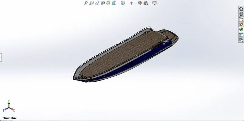
Features used:
In Sketch
- Line
- Spline
- Circle
- Rectangle
- Arc
- Slot
- 3-D Sketch
- Sketch picture
In Surfaces
- Extruded Surface
- Revolved Surface
- Lofted Surface
- Surface Trim
- Surface Fill
- Surface Knit
- Delete Face
In Features
- Project Curve
- Chamfer
- Fillets
- Reference Plane
- Split
- Split Line
- Extruded BossBase
- Extruded Cut
- Mirror
2. Front Seat:
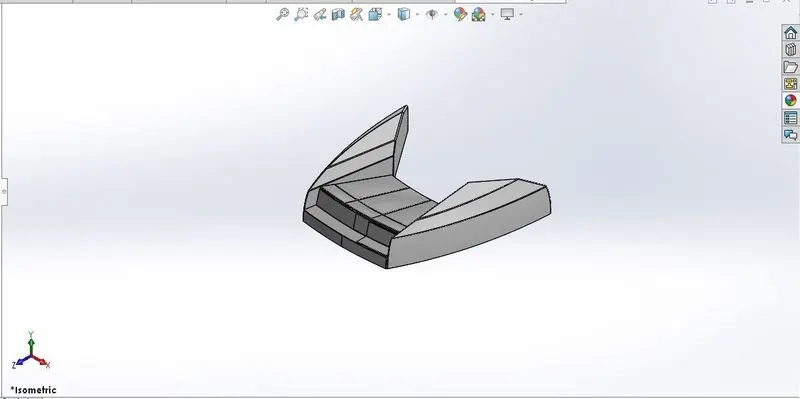
COMMANDS USED TO MODEL
In Sketch
- Sketch Picture
- Line
- Spline
- Circle
- Arcs
In Surfaces
- Extruded Surface
- Lofted Surface
- Trim Surface
- Filled Surface
- Knit Surface
- Swept Surface
- Revolved Surface
In Features
- Extruded Cut
- Revolved Boss/Base
- Chamfer
- Fillet
- Mirror
- Dome
3. Middle Seat: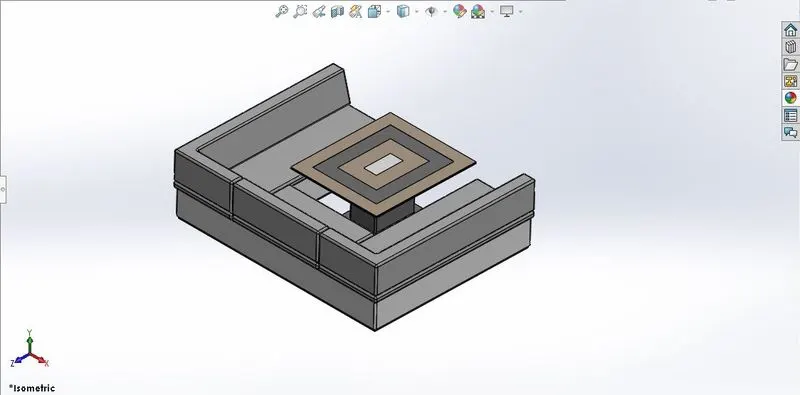
COMMANDS USED TO MODEL
In Sketch
- Sketch Picture
- Line
- Rectangle
In Features
- Extruded Boss/Base
- Chamfer
- Fillet
- Mirror
- Reference Plane
4. Rear seat:
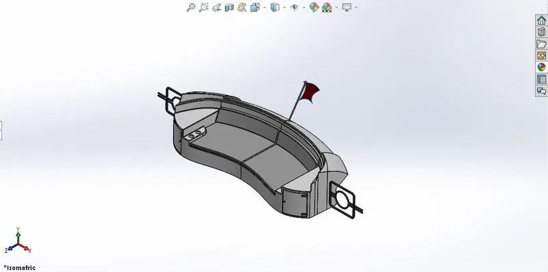
COMMANDS USED TO MODEL
In Sketch
- Sketch Picture
- Line
- Spline
- Circle
- Arcs
- Rectangle
In Surfaces
- Swept Surface
- Extruded Surface
- Off-set Surface
- Filled Surface
- Knit Surface
- Ruled Surface
- Lofted Surface
In Features
- Reference Plane
- Extruded Boss/Base
- Revolved Boss/Base
- Fillet
- Mirror
5. Radar:
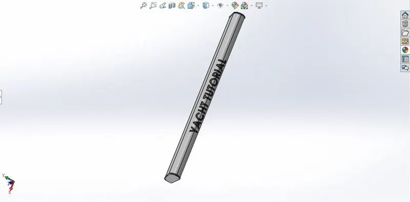
COMMANDS USED TO MODEL
In Sketch
- Line
- Text
- Circle
- Point
In Features
- Extruded Boss/Base
- Extruded Cut
- Sketch Pattern
- Fillet
- Mirror
- Split Line
6. Radar Mast:
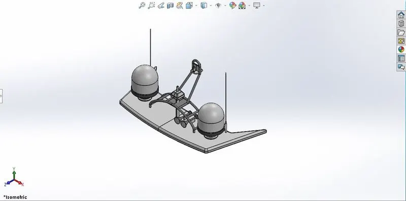
COMMANDS USED TO MODEL
In Sketch
- Sketch Picture
- Line
- Spline
- Rectangle
- Arcs
In Feature
- Extruded Boss/Base
- Lofted Boss/Base
- Revolved Boss/Base
- Swept Boss/Base
- Reference Plane
- Projected Curve
- Fillet
- Mirror
- Dome
- Shell
7. Garage Door:
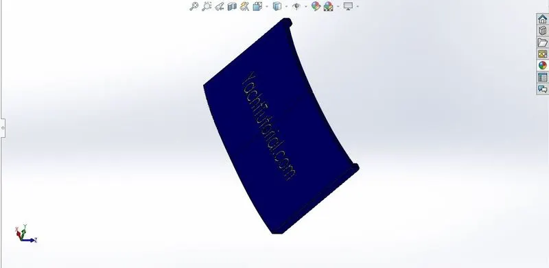
Features used to create a garage door:
- Shell
- Chamfer
- Fillet
- Extrude cut
- Text
- Mirror
8. Superstructure:
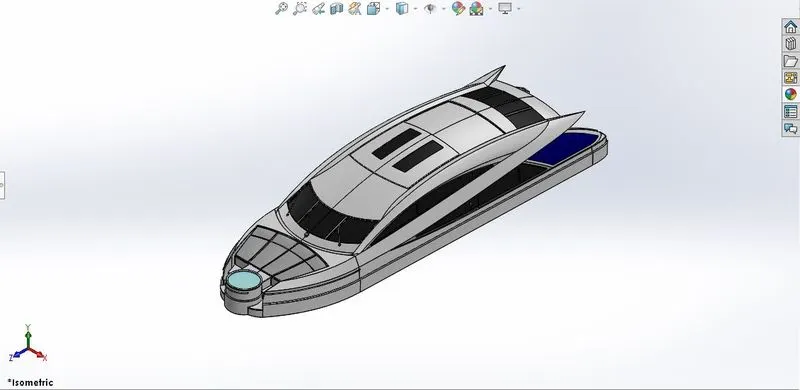
COMMANDS USED TO MODEL
In Sketch
- Sketch Picture
- 3D Sketch
- Line
- Spline
- Circle
- Rectangle
- Center Point Arc
- Convert Entities
In Surfaces
- Extruded Surface
- Swept Surface
- Ruled Surface
- Knit Surface
- Trim Surface
- Extend Surface
- Filled Surface
- Lofted Surface
- Revolved Surface
- Fillet
- Chamfer
In Features
- Project Curve
- Reference Curve
- Split
- Split Line
9. Propeller
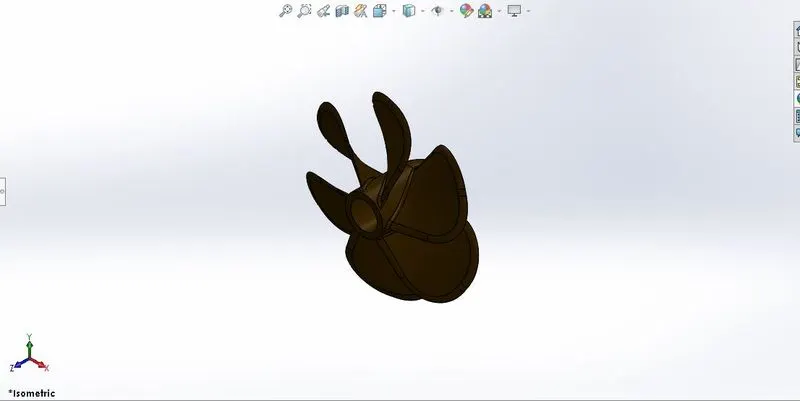
COMMANDS USED TO MODEL
In Sketch
- Spline
- Circle
- Line
In Features
- Revolved Boss/Base
- Lofted Boss/Base
- Extruded Cut
- Reference Plane
- Circular Pattern
- Fillet
Assembly of the american predator yacht:
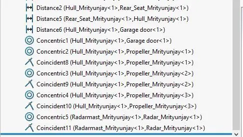
The following mates are used to assemble the different parts of the yacht in proper places.
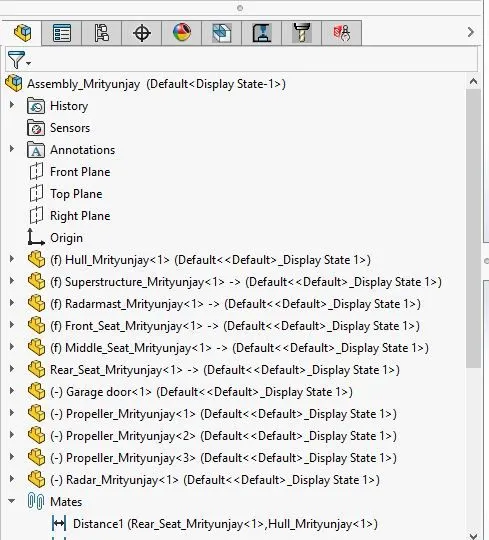
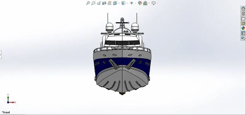
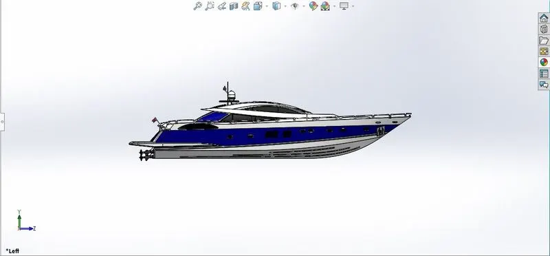
Images of assembled Sunseeker Predator Yacht:
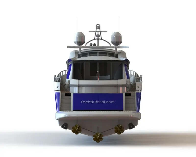
Front View:
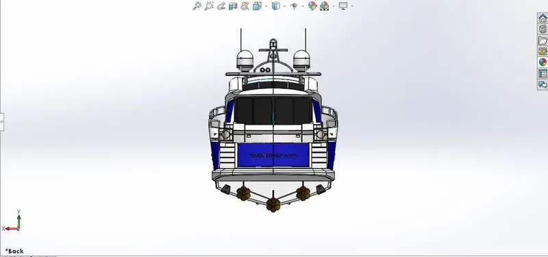
Back view:
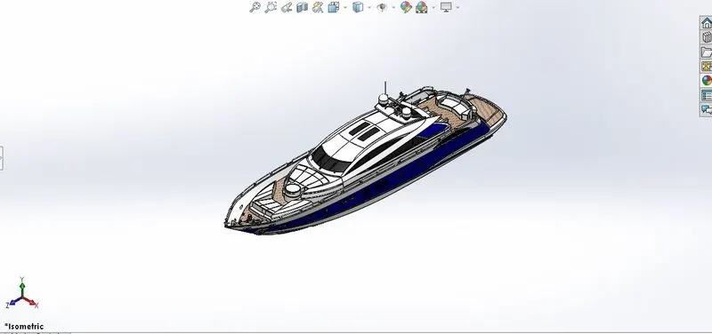
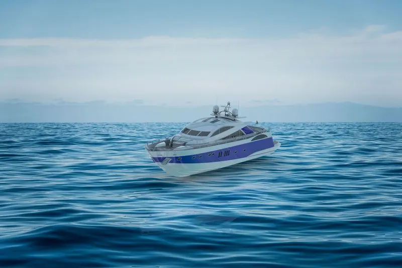
Isometric View:
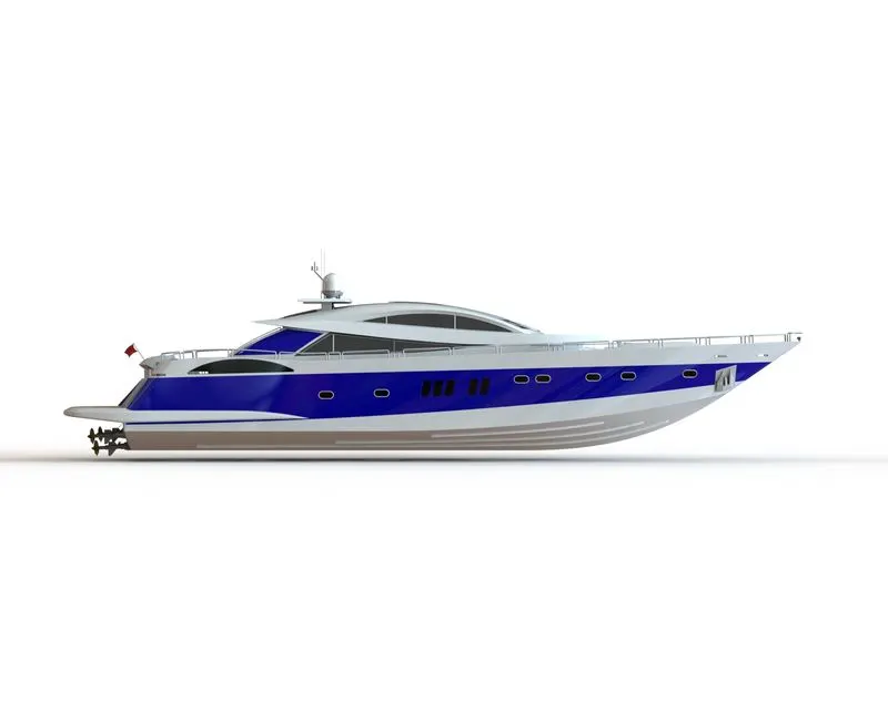
Side View:
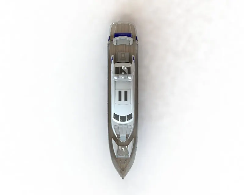
Top View:
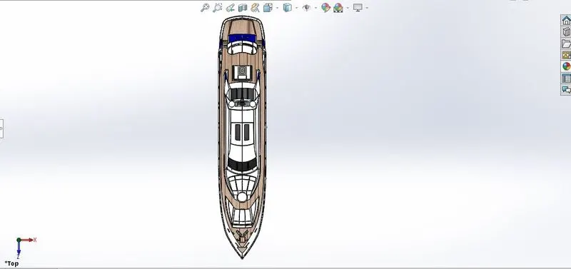
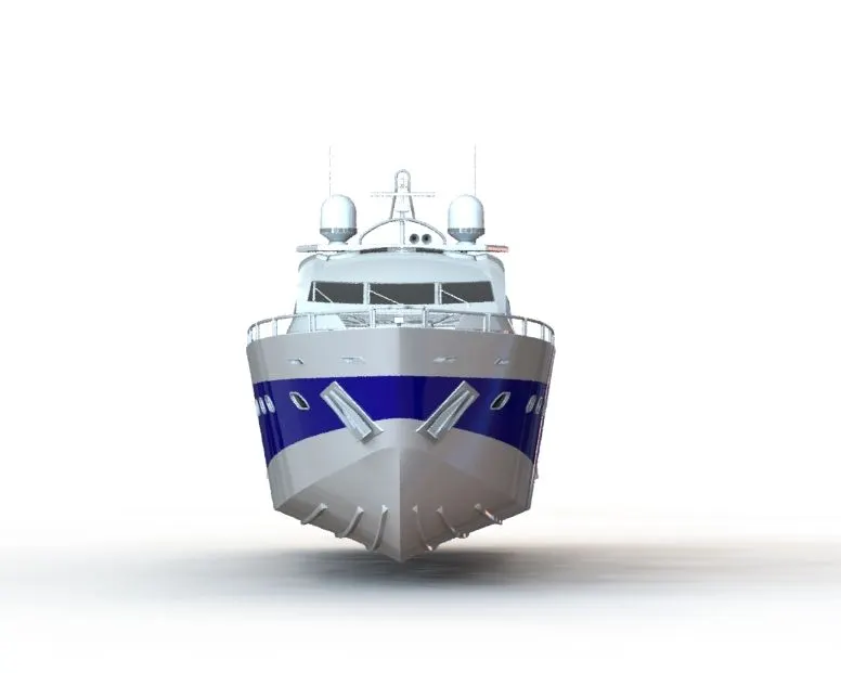
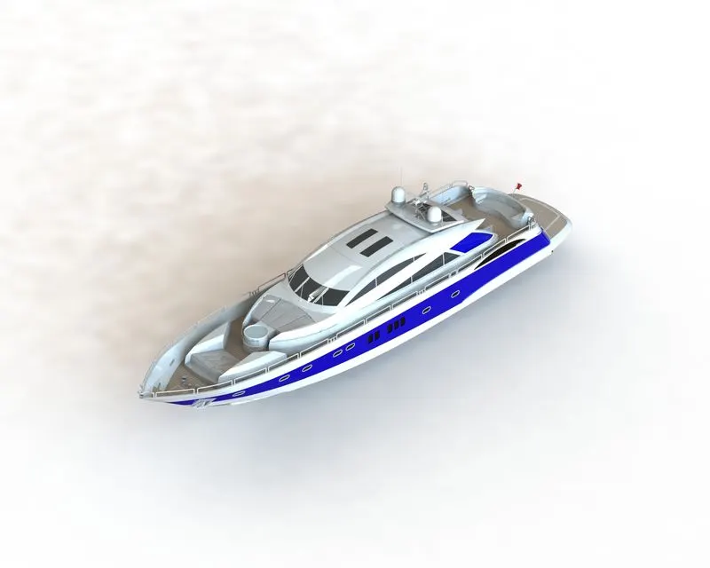
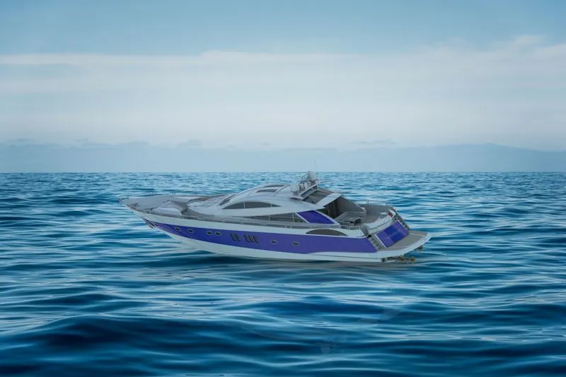
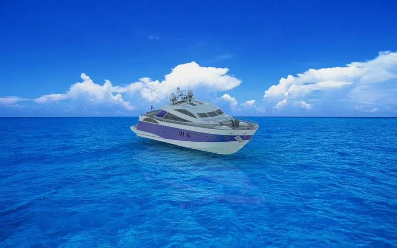
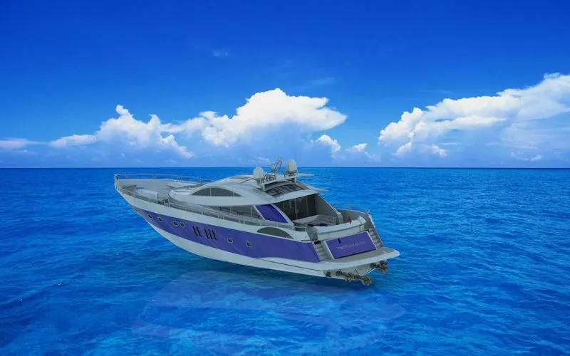
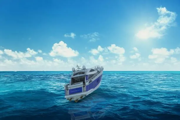
Photo realistic images of rendered assembly of American Predator Yacht: The rendering work is done on Photoview 360. (I was not able to use solidworks visualize as my system was not able to run that software.)

Conclusion:
The above work presented explains how the American predator yacht was created from the scratch. Awhile working on this project my knowledge of Solidworks has enhanced.
Thank you.
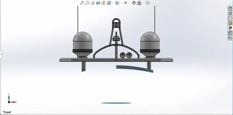
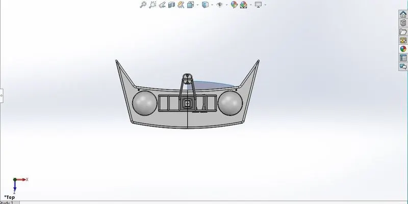
For the present challenge, below I am attaching the different views of radar mast and its feature tree as instructed.
Front View:
Top view:
Side View: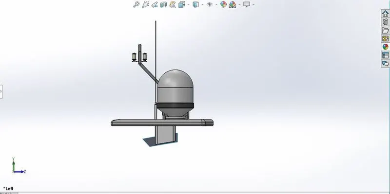
Isometric view:
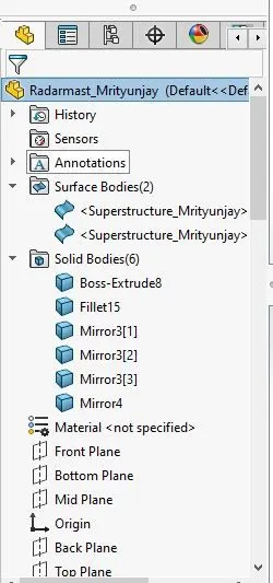
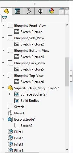
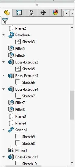
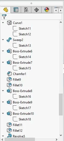
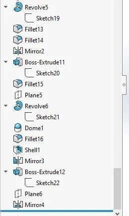
Feature Tree: