Radar Mast & Final Assembly of Yacht
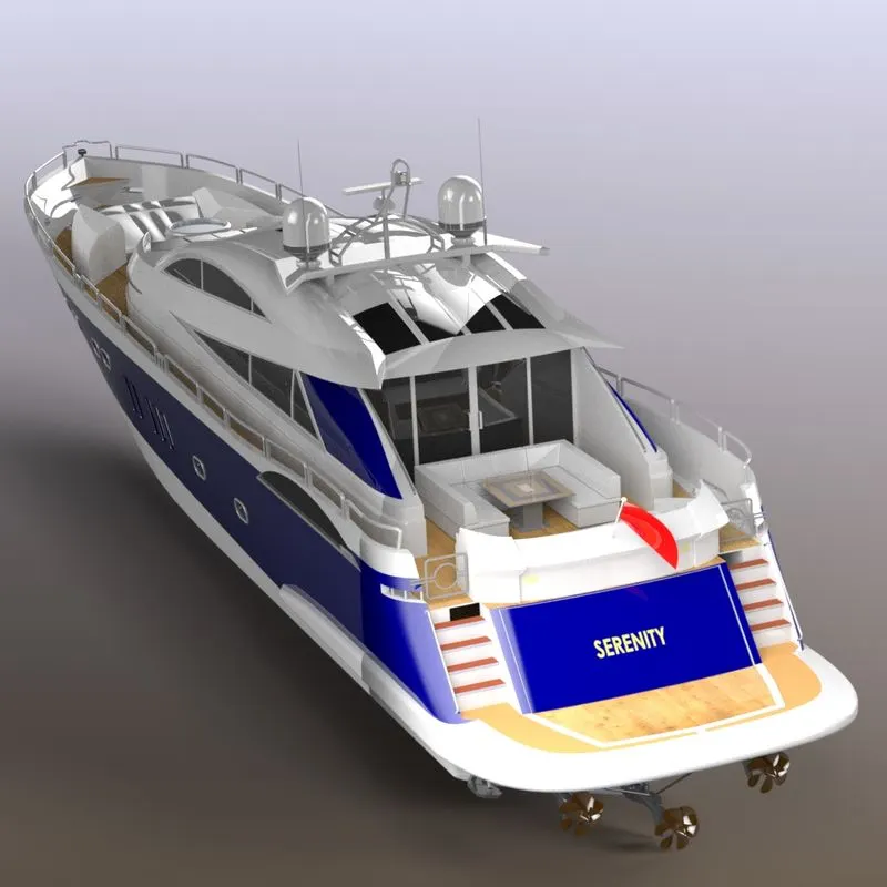
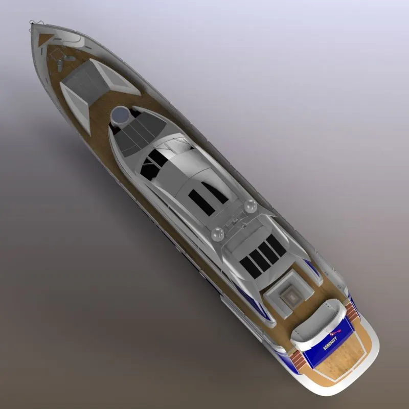
Objective: The main objective of the project is to sketch and build a complete "Sunseeker Predator Yacht" using Solidworks and adding the appearences as suitable and required decals to the assembled yacht.
Yacht:
A yacht is a type of boat which is mainly used for recreation.lt usually has a cabin, so it does not need to return to the harbour overnight. Originally, yachts were sailing-boats, but now there are also motor yachts. The name comes from the Dutch word jachtschip, which originally meant hunting-boat or fast boat. Yachts have a fixed keel. A large motor yacht in Lorient, Brittany, France A yacht can vary in size from about 20 feet (6 metres) to 200 feet (60 metres) or more. Most privately owned yachts fall in the range of about 7 metres (23 ft)-14 metres (46 ft); the cost of building and keeping a yacht rises quickly as length increases. In the United States, sailors tend to refer to smaller yachts as sailboats, while referring to the general sport of sailing as yachting. In sailboat racing, a yacht is any sailing vessel taking part in a race.
Introduction:
SolidWorks is a solid modeling computer-aided design (CAD) and computer-aided engineering (CAE) computer program that runs primarily on Microsoft Windows. While it is possible to run SolidWorks on MacOS, it is not supported by SolidWorks. SolidWorks is published by Dassault SystOmes. SOLIDWORKS is used to develop mechatronics systems from beginning to end. At the initial stage, the software is used for planning, visual ideation, modeling, feasibility assessment, prototyping, and project management. The software is then used for design and building of mechanical, electrical, and software elements.
Design Methodology:
SolidWorks is a parasolid-based solid modeler, and utilizes a parametric feature-based approach to create models and assemblies.
Parameters refer to constraints whose values determine the shape or geometry of the model or assembly. Parameters can be either numeric parameters, such as line lengths or circle diameters, or geometric parameters, such as tangent, parallel, concentric, horizontal or vertical, etc. Numeric parameters can be associated with each other through the use of relations, which allows them to capture design intent. Design intent is how the creator of the part wants it to respond to changes and updates. For example, you would want the hole at the top of a beverage can to stay at the top surface, regardless of the height or size of the can. SolidWorks allows you to specify that the hole is a feature on the top surface, and will then honor your design intent no matter what the height you later gave to the can. Features refer to the building blocks of the part. They are the shapes and operations that construct the part. Shape-based features typically begin with a 2D or 3D sketch of shapes such as bosses, holes, slots, etc. This shape is then extruded or cut to add or remove material from the part. Operation-based features are not sketch-based, and include features such fillets, chamfers, shells, applying draft to the faces of a part, etc.Screen shot captured from a SolidWorks top-down design approach. Building a model in SolidWorks usually starts with a 2D sketch (although 3D sketches are available for power users). The sketch consists of geometry such as points, lines, arcs, conics (except the hyperbola), and splines. Dimensions are added to the sketch to define the size and location of the geometry. Relations are used to define attributes such as tangency, parallelism, perpendicularity, and concentricity. The parametric nature of SolidWorks means that the dimensions and relations drive the geometry, not the other way around. The dimensions in the sketch can be controlled independently, or by relationships to other parameters inside or outside of the sketch.
SolidWorks pioneered the ability of a user to roll back through the history of the part in order to make changes, add additional features, or change the sequence in which operations are performed.Later feature-based solid modeling software has copied this idea. In an assembly, the analog to sketch relations are mates. Just as sketch relations define conditions such as tangency, parallelism, and concentricity with respect to sketch geometry, assembly mates define equivalent relations with respect to the individual parts or components, allowing the easy construction of assemblies. SolidWorks also includes additional advanced mating features such as gear and cam follower mates, which allow modeled gear assemblies to accurately reproduce the rotational movement of an actual gear train. Finally, drawings can be created either from parts or assemblies. Views are automatically generated from the solid model, and notes, dimensions and tolerances can then be easily added to the drawing as needed. 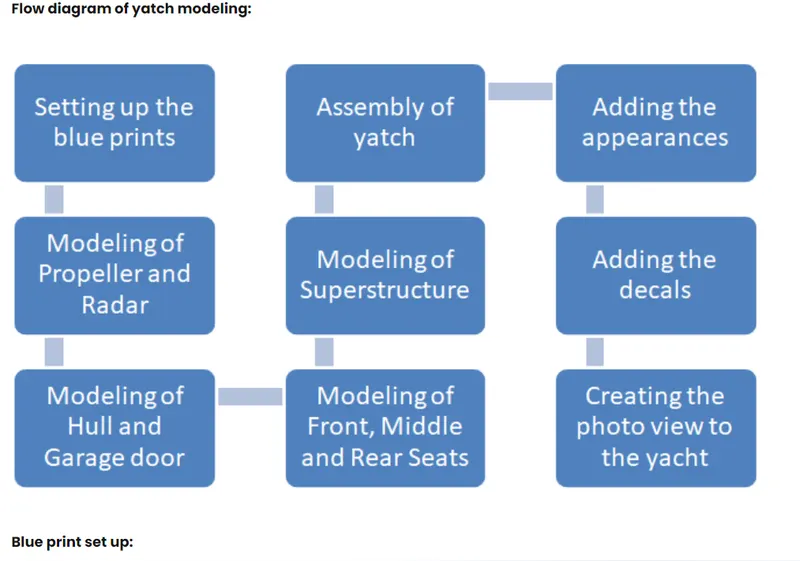
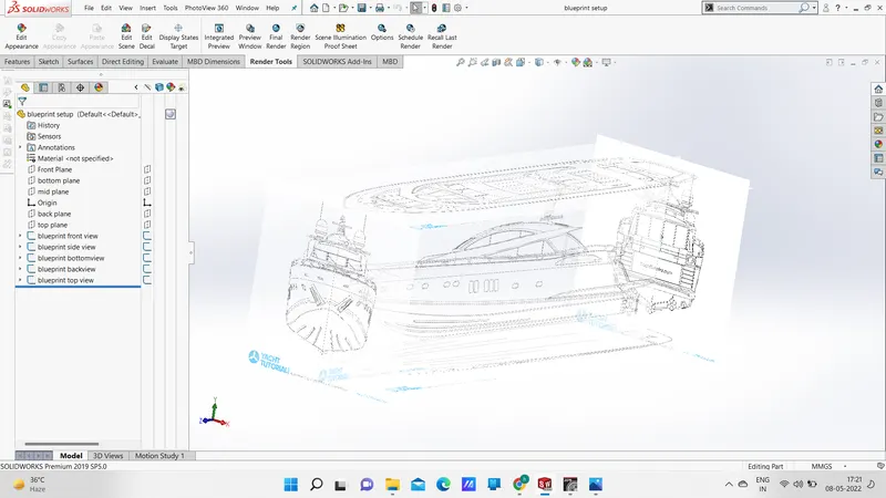
Different parts in yatch:
Propeller
Radar
Hull
Garage door
Front seat
Middle seat
Rear seat
Superstructure
Radar mast
Description of the parts:
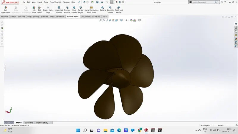
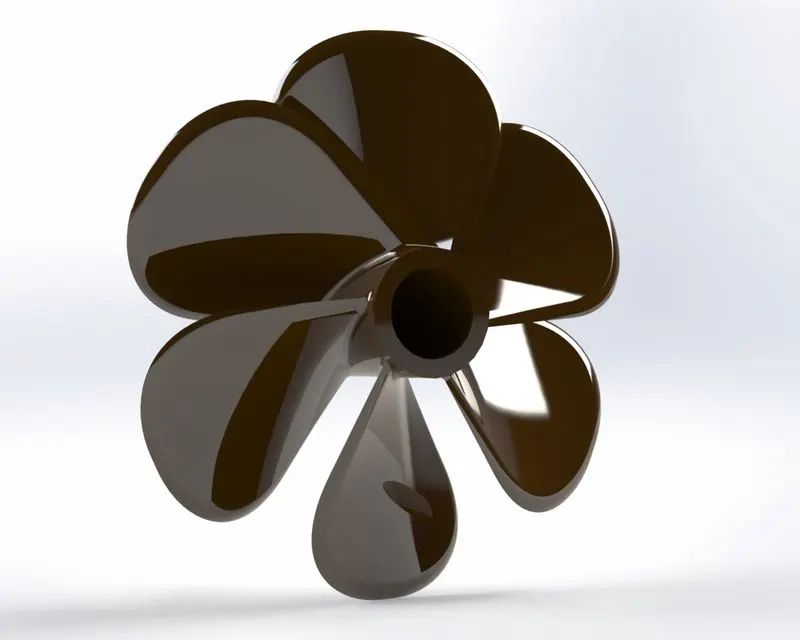
#Propeller: A propeller is a rotating fan-like structure which is used to propel the ship by using the power generated and transmitted by the main engine of the ship. A propeller is a device with a rotating hub and radiating blades that are set at a pitch to form a helical spiral, that, when rotated, performs an action which is similar to Archimedes' screw. It transforms rotational power into linear thrust by acting upon a working fluid, such as water or air.The rotational motion of the blades is converted into thrust by creating a pressure difference between the two surfaces. A given mass of working fluid is accelerated in one direction and the craft moves in the opposite direction. Propeller dynamics, like those of aircraft wings, can be modelled by Bernoulli's principle and Newton's third law.Most marine propellers are screw propellers with helical blades rotating on a propeller shaft with an approximately horizontal axis.
#Radar:
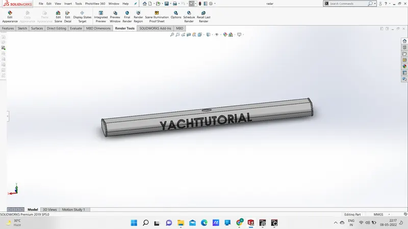
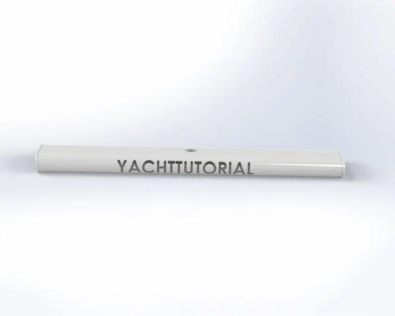
Marine Radar - Radio Detection and Ranging, is used to detect objects and their position relative to your current location.... A marine radar device acts as a major navigation aid for boaters. It helps in detecting boats, birds, landmasses, and weather systems - even if the visibility is less than usual. Marine radars are X band or S band radars on ships, used to detect other ships and land obstacles, to provide bearing and distance for collision avoidance and navigation at sea. They are electronic navigation instruments that use a rotating antenna to sweep a narrow beam of microwaves around the water surface surrounding the ship to the horizon, detecting targets by microwaves reflected from them, generating a picture of the ship's surroundings on a display screen. Radar is a vital navigation component for safety at sea and near the shore. Captains need to be able to maneuver their ships within feet in the worst of conditions and to be able to navigate "blind", when there is no visibility at night or due to bad weather. In addition to vessel-based marine radars, in port or in harbour, shore-based vessel traffic service radar systems are used by harbormasters and coast guard to monitor and regulate ship movements in busy waters. Radars are rarely used alone in a marine setting. A modern trend is the integration of radar with other navigation displays on a single screen, as it becomes quite distracting to look at several different screens. Therefore, displays can often overlay an electronic GPS navigation chart of ship position, and a sonar display, on the radar display. This provides a combined view of surroundings, to maneuver the ship.
Some import tools used to model the Radar is line, spline, circular pattern, boss extrude, cut extrude, fillet, sketch pattern, mirror etc.,
Modeling of the Radar
#Hull:
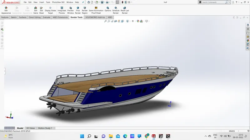
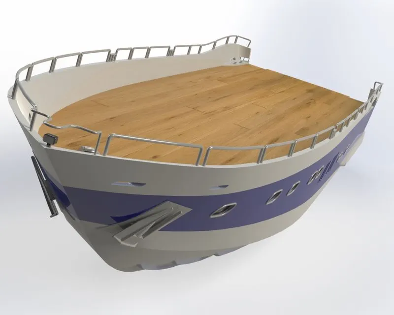
The hull of a ship is the most notable structural entity of the ship. To define the hull, it can be said that it is the watertight enclosure of the ship, which protects the cargo, machinery, and accommodation spaces of the ship from the weather, flooding, and structural damage. A hull is the watertight body of a ship or boat. The hull may open at the top (such as a dinghy), or it may be fully or partially covered with a deck. Atop the deck may be a deckhouse and other superstructures, such as a funnel, derrick, or mast. The line where the hull meets the water surface is called the waterline.
Steel is one of the most popular materials used for boats and has consistently been the material of choice for the past century. Its high strength, durability, resistance to abrasion, and relatively low cost are some of the main reasons why steel is widely used in the industry. There is a wide variety of hull types that are chosen for suitability for different usages, the hull shape being dependent upon the needs of the design. Shapes range from a nearly perfect box in the case of scow barges to a needle-sharp surface of revolution in the case of a racing multihull sailboat. The shape is chosen to strike a balance between cost, hydrostatic considerations (accommodation, load carrying, and stability), hydrodynamics (speed, power requirements, and motion and behavior in a seaway) and special considerations for the ship's role, such as the rounded bow of an icebreaker or the flat bottom of a landing craft. In a typical modern steel ship, the hull will have watertight decks, and major transverse members called bulkheads. There may also be intermediate members such as girders, stringers and webs, and minor members called ordinary transverse frames, frames, or longitudinals, depending on the structural arrangement. The uppermost continuous deck may be called the "upper deck", "weather deck", "spar deck", "main deck", or simply "deck". The particular name given depends on the context—the type of ship or boat, the arrangement, or even where it sails.
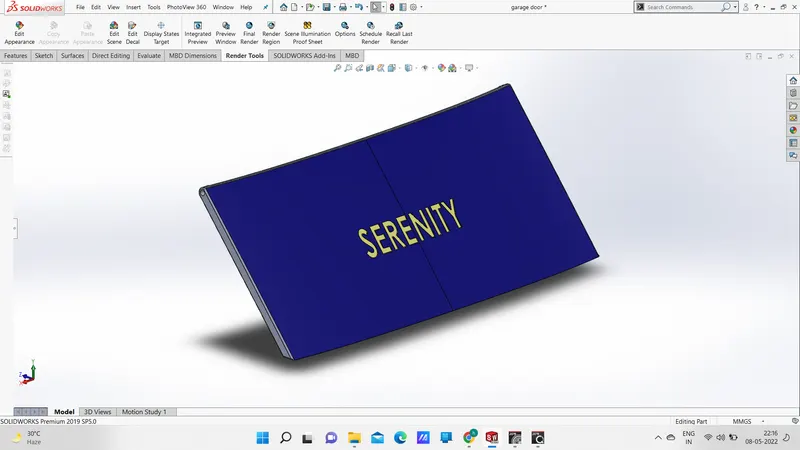
#Garage door:
The main purpose of the garage door is to open and close the hull inside body. In the garage, there are two door types; there is the door that goes from the inside of the garage to the outside yard, this is just a regular exterior door you can buy easily. Then you have the door that goes from inside the garage to inside the house, this door is special, and it's called a fire door. Some of the import tools used to model the garage door are line, spline, mirror, split line, fillet, cut extrude, shell etc.,
Modeling of the Garage door

#Front, middle and rear seats:
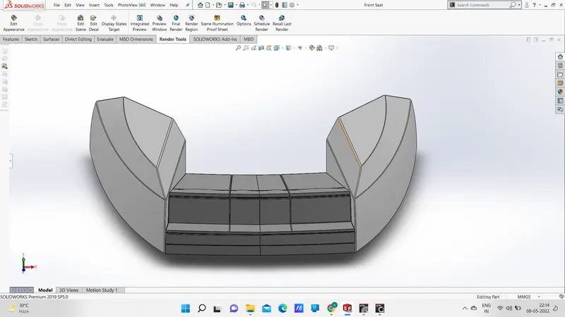
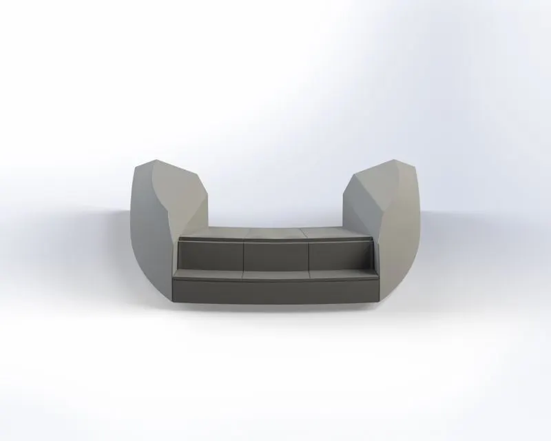
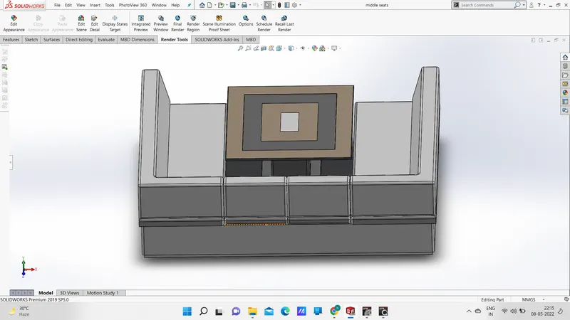
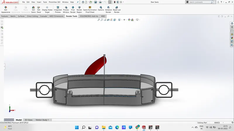
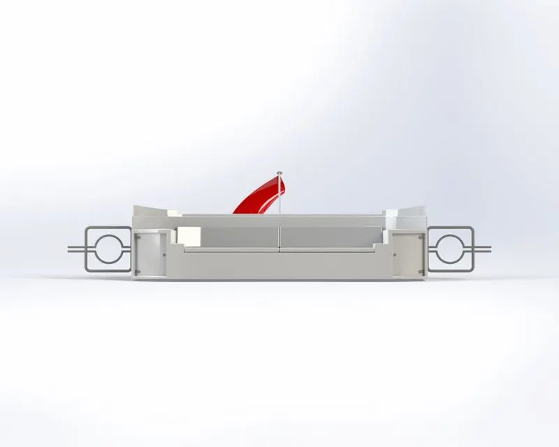
The yacht seats are mainly used for the passenger comfort and their luxuary. Some important tools whicha are required for model the yacht are surface swwep, surface fill, surface trim, surface loft, chamfer, revolve, cut extrude, mirror, fillet, cut extrude etc., Modeling of the Front seat
Front Seat Modelling
Middle Seat Modelling
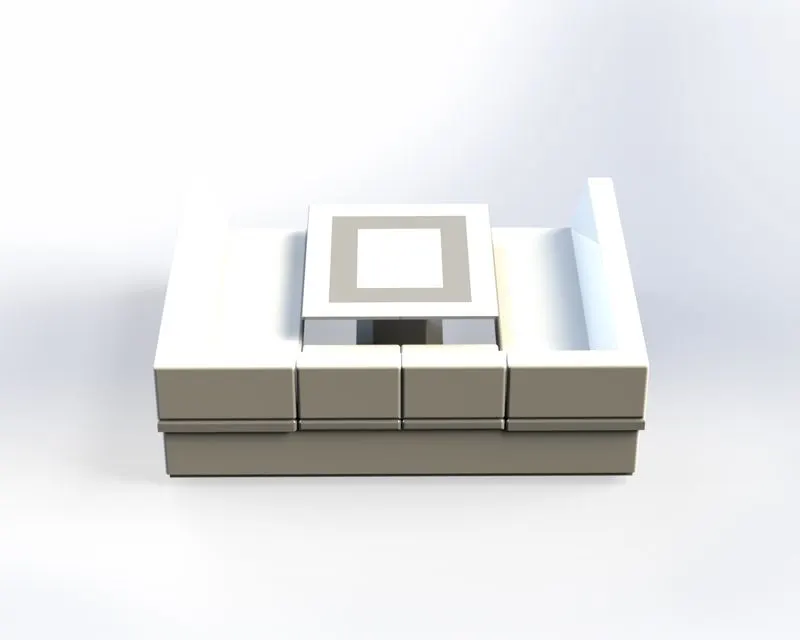
Rear Seat Modelling
#Superstructure
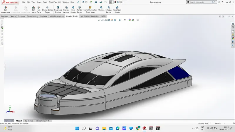
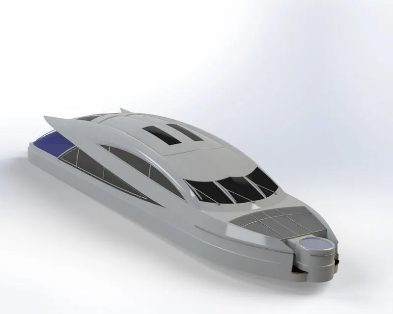
The superstructure covers everything above the substructure, from walls to floors to roofing. The purpose of the superstructure is to enclose and divide space, as well as spread loads safely into the substructure. A superstructure is an extended construction of any building or platform that rises above the rest of the building or platform in a distinct manner. The word comes from a combination of two Latin words, the Latin prefix 'super' means in addition or above or in excess of, whereas the stem word 'structure' means to build or to heap up. Thus, superstructure means to add a construction to an already existing structure. In ships this is the name given to the part of the ship that emerges from the deck. However any mast, sails, any armaments or arsenal are not included in this category. The size of the superstructure has a great influence on the mobility of the vessels. They are designed in a manner, so that, they add value and hinder the speed and mobility in the least. The superstructure is mostly designed in fashion as well. This is because it is the most easily visible part of the ship, in fact it is the identification of the ship, and so the designers try to provide it with the identity that is unique. Some important tools used to build the superstructure is line, circle, corner rectangle, surface extrude, surface sweep, surface knit, surface loft, surface trim, projrctive curve, ruled surface, surface extend, sweep, boss extrude, cut extrude, chamfer etc.,
Modeling of the Superstructure
#Radar mast:
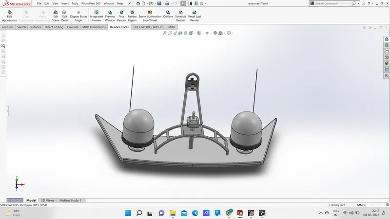
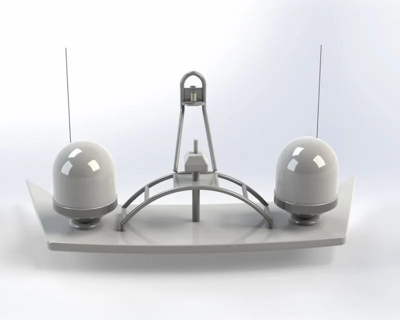
Its purposes include carrying sails, spars, and derricks, and giving necessary height to a navigation light, look-out position, signal yard, control position, radio aerial or signal lamp. Large ships have several masts, with the size and configuration depending on the style of ship. Some important tools which are required for build the yacht are line, mirror, sweep, chamfer, fillets, revolve, boss extrude, shell etc.,
Modeling of the Radar Mast
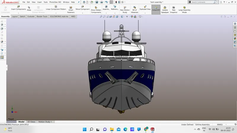
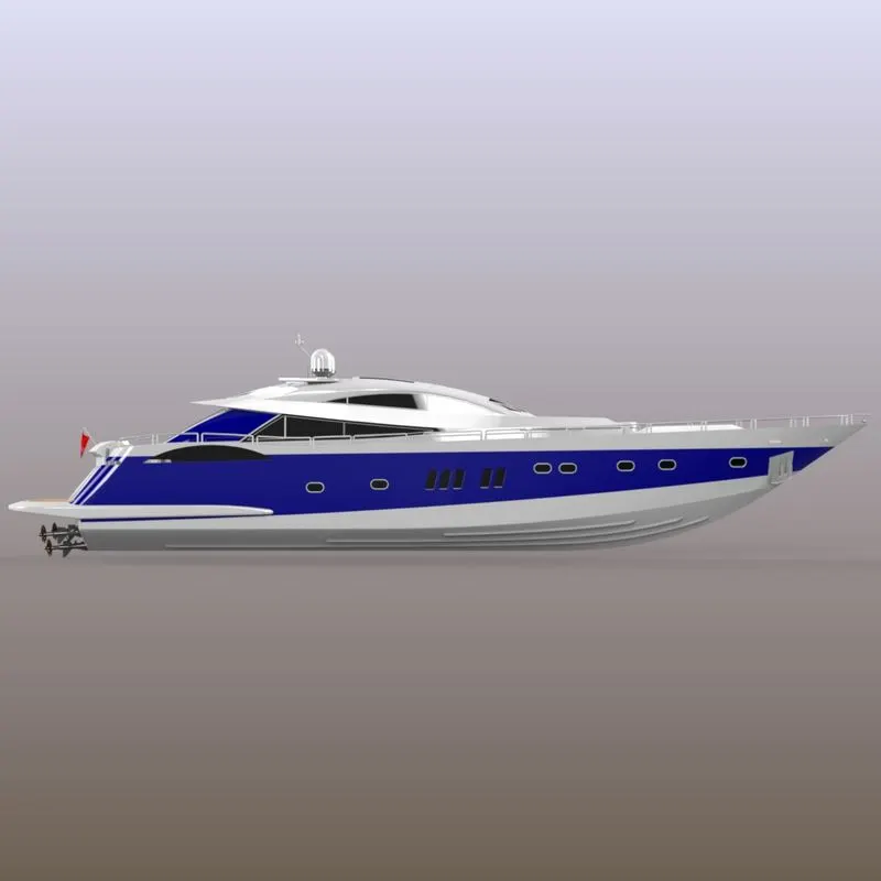
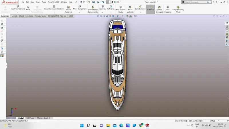
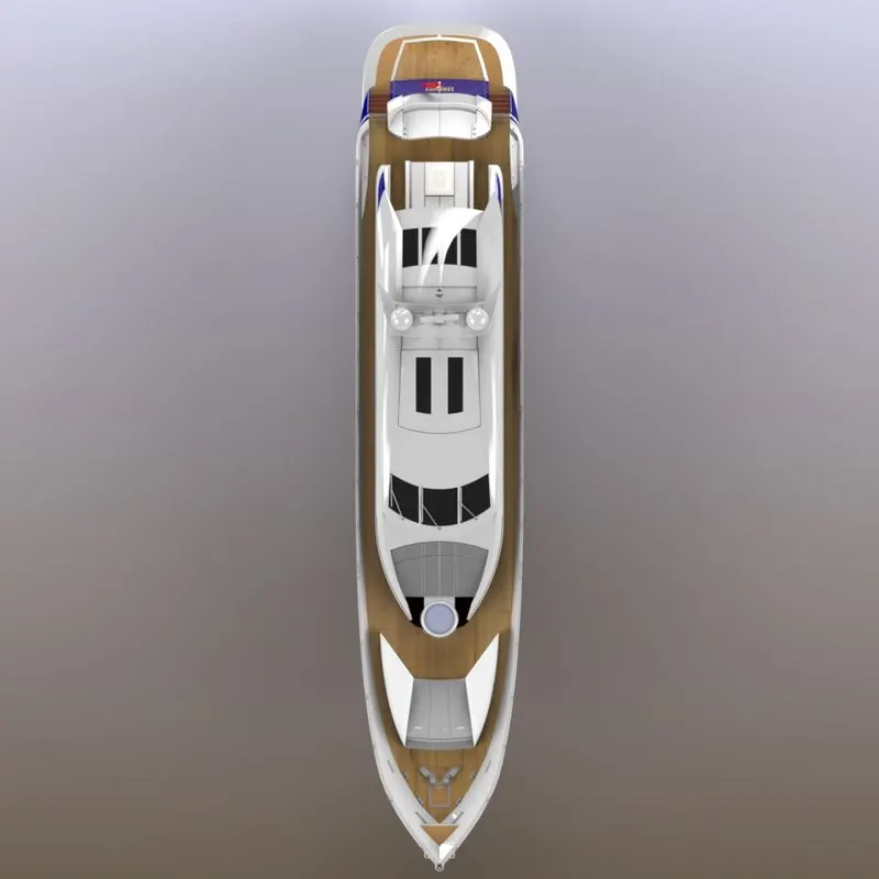
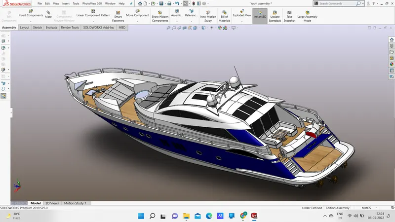
Assembly: Assembling is the process of combaning the different parts with a sequence of joining through advanced mates like coincident, distance, angle, concentric, parallel, width, limit angle, etc.,
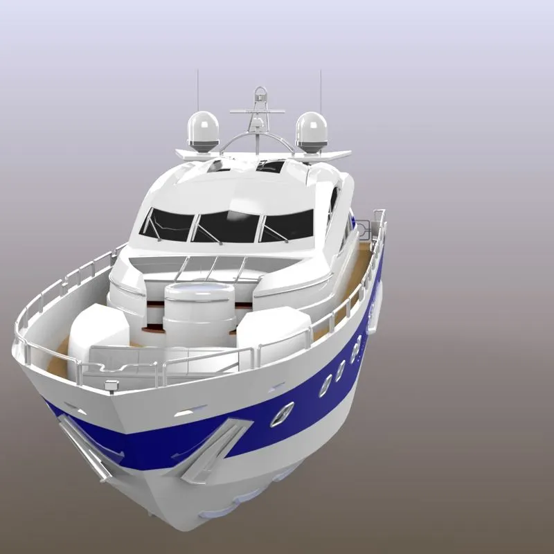
Front view of yacht assembly
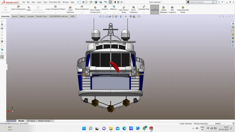
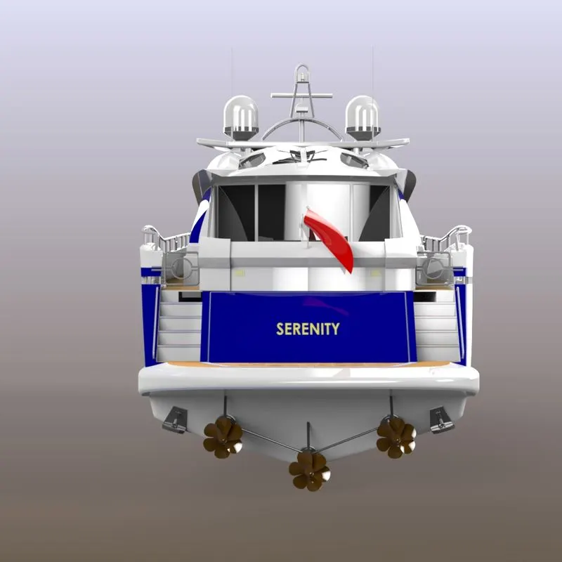
Back side view
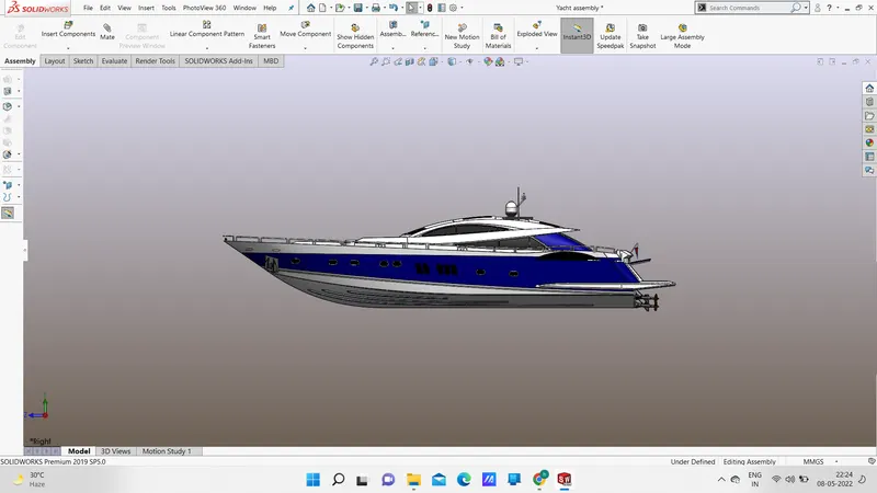
Side View
Top view
Isometric View
Conclusion:
By this project i am able to learn how to design the component in the solidworks, how to assemble the different parts by using the advanced mates, how to modeled the component and how to create the photo realistic rendering for yacht. Finally the required views and documentation is provided.
Google Drive Link for Yacht Assembly-
https://drive.google.com/drive/folders/19bLSnfk4P0JLnk_3xrW81t6HfQ9lKNAf?usp=sharing