Radar Mast & Final Assembly of Yacht
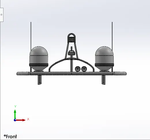
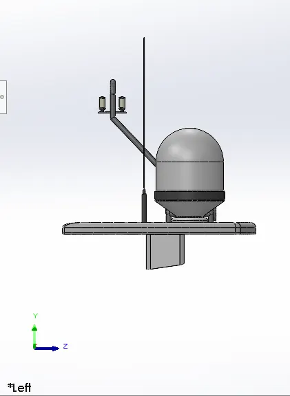
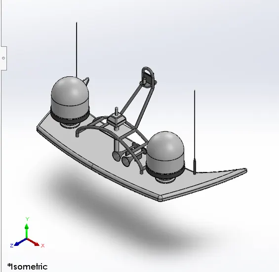
1.RADAR MAST
Front view
Left view
Isometric view
2.YACHT ASSEMBLY
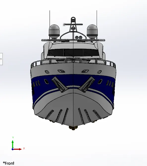
Front view
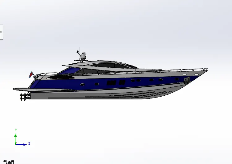
Left View
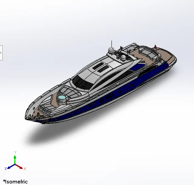
Isometric view
Project report on Sunseeker Yacht Assembly
Title of the Project:Modelling of Sunseeker Predator Yacht
Aim&Objective:
- To create different parts of a Sunseeker Predator Yacht in Solidworks using various types of sketches,features and surfacing tools
- To assemble the different modelled parts to create a yacht
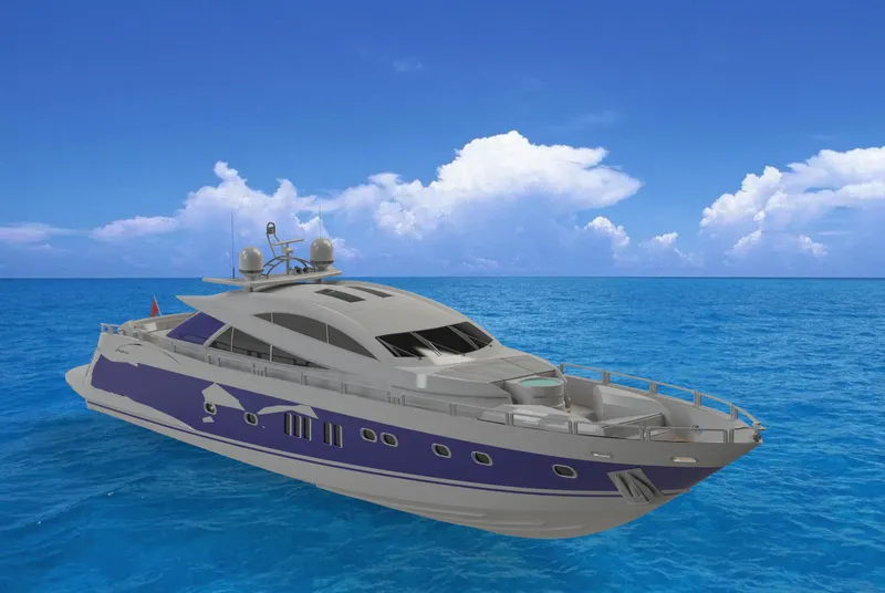
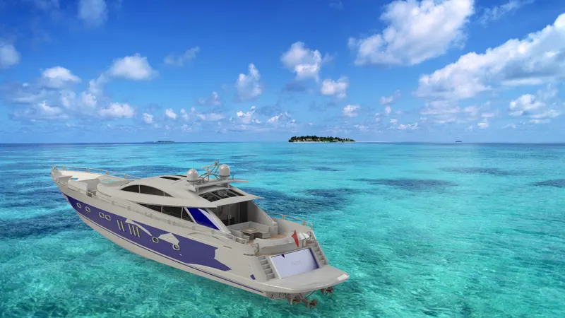
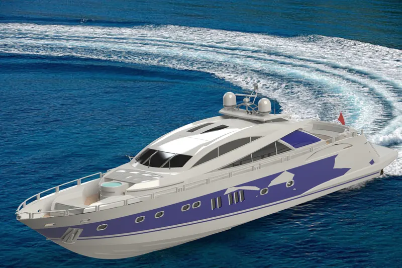
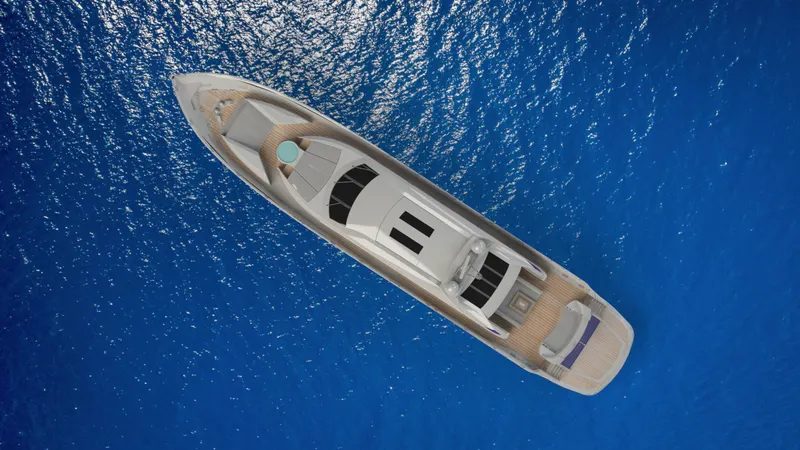
- To create photorealistic rendered images of Yacht using Solidworks Visualize
INTRODUCTION:
Sunseeker is popular for their Cruisers,High performance and sports cruiser among other classes and models.These boats have a deeper draft and very wide beam,features that make them perfect for overnight cruising,day cruising and sports cruising.
In this project we learn the entire modelling of Sunseeker Yacht on Solidworks and Solidworks visualize.The parts were modelled separately and they were assembled to create a Sunseeker Predator Yacht.
The Different components of yacht we dealt with are
- Propeller
- Radar
- Blueprint setup
- Hull
- Garage door
- Front seat
- Middle seat
- Rear seat
- Superstructure
- Radar mast
DESIGN METHODOLOGY:

1.Propeller
A Propeller is a device with rotating hub and radiating blades that are set at a pitch to form Helical Spiral that when rotated,exerts linear thrust upon a working fluid ,such as water or air.Propellers are used to pump fluid through a pipe or duct,or to create thrust to propel a boat through water.Most marine propellers are screw propellers with helical blades rotating on a propeller shaft with an approximately horizontal axis.
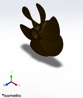
In this Model I Have used following features i.e;
a)Revolve:
Create a sketch that contains a centre line,or edge to use as the axis around which the feature revolves.To create a revolve,Go to Insert >Boss/Base>Revolve
b)Loft:
The Loft feature in Solidworks allows to generate complex geometry in a single feature.It does this by interpolating surfaces between various cross-sections can be sketches,faces or edges.
To create a solid loft,Go to Insert>Boss/Base>Loft or click on the Loft icon
c)Fillet:
Fillet creates a rounded internal or external face on the part.It fillets all edges of face,selected sets of faces,selected edges.
d)Cut extrude:
It's a tool to remove material by projecting a sketched section normal to the sketching plane.
To create an extruded cut :
- Sketch the profile for cut
- Click Extruded Cut on the Features toolbar or select Insert>Cut>Extrude on the menu bar
e)Circular Pattern:
Use circular pattern to create multiple instances of one or more features that you can space uniformly around an axis.
To create a circular pattern:
- Create one or more features to replicate.
- Click Circular Pattern in Features toolbar or Insert>Pattern/Mirror >Circular Pattern
- Set the Property Manager options
- In Parameters adjust the angle,Number of instances
- Select the Equal spacing,Geometry Pattern,Propagate Visual Properties option
- Set ok
2.Radar:
Radar detects other ships and land obstacles and distance for collision avoidance and navigation while on water.It also helps in detecting birds and weather systems ,even if the visibility is less than usual.
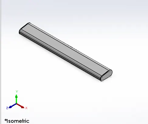
In this modelling, features dealt with are Boss/Base extrude,Cut extrude,Fillet,Mirror,Sketch pattern,Split line.
a)Boss Extrude
An Extruded Boss/Base feature will allow us to take a 2d sketch and add thickness to it in third dimension.
To create a Extruded surface:
- Create a sketch
- Click Extruded Boss/Base on the Features toolbar or Click Insert>Boss/Base>Extrude
- Sketched part gets extruded which we can give a distance.
- There are options for extruded in Direction option such as Blind,Up to vertex,Up to surface ,Offset from surface,Up to body
- Select any option
- Set ok
b) Mirror:
To Mirror a feature,Click Mirror in Features toolbar or Click Insert>Pattern/Mirror>Mirror.
In Mirror Face/Plane,we can select plane or faces from the part.There are options such as Features to Mirror and Bodies to Mirror.Select the Appropriate one ,Enable the Merge solids,Enable the Knit surfaces,Enable the Propagate Visual properties and set ok.
c)Split line:
Using the split lines feature,the sketch lines are projected onto the selected faces and divide the faces into multiple regions as defined by the sketch.Once the split line is created,these selected regions can have a different appearance than the other regions and function as a separate face.
3.Blueprintsetup:
- A blueprint is a guide for making something-its a design or pattern that can be followed.
- Here various Blueprints were created for different views of the yacht i.e:Front view,Backview,Top view,Bottom view,Side view.
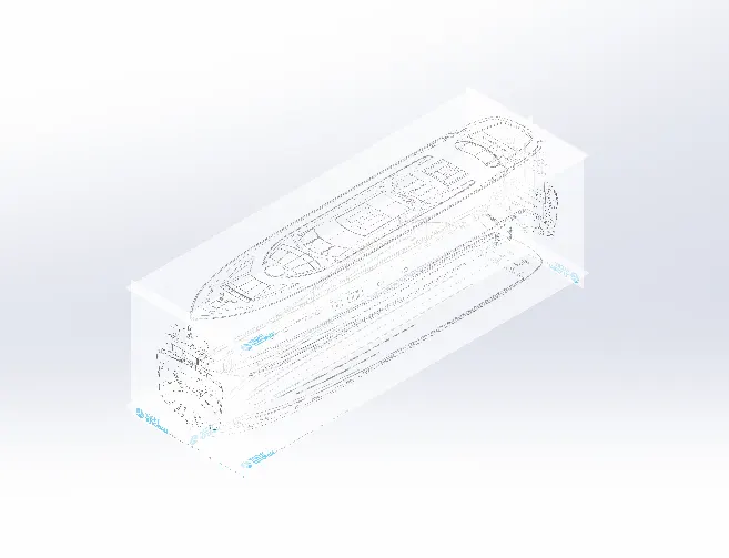
Commands used:Following were the commands were used to set the blueprint
- Sketch picture
- Reference plane
- 2D sketch
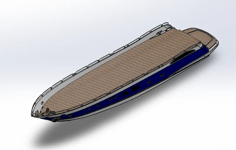
4.HULL
It is the watertight enclosure of the yacht,which protects the cargo,machinery and accommodation spaces of the yacht from the weather,flooding and structural damage.The Hull may be open at the top or it may be fully or partially covered with a deck.At the top of the deck may be a superstructure or deckhouse will be there.
Commands used:Following were the commands used to model the part,
In Sketch:
- Line
- Spline
- Circle
- Rectangle
- Arc
- Slot
- 3D sketch
- Sketch picture
In Surfaces:
a)Extruded surface
Extrudes a sketch or selected sketch contours in one or two direction to create a surface feature.To Create a Surface extrude Click Insert>Surface>Extrude
b)Lofted surface
Creates a lofted profiles between two or more profiles or sketches Specify Start and End constraints and add guide curve to control the path shape
c)Trim Surface
It Trims the surfaces where a surfaces intersect with another surface ,a plane or a sketch.To trim the surface Go to Insert>Surface>Trim or click on trim icon.
In Selection part we can select keep selection or remove selection based on our removal process of our part .There are other split options we can select such as Split all,Natural,Linear.
d)Surface Fill
Patches a surface within a boundary defined by edges,sketches,or curves .We can use constraint curves to fill surfaces and adjust resolution control to improve surface finish.
e)Surface Knit
It combines two or more adjacent,non-intersecting surfaces into a single single surface body.If the resulting knit surface encloses a volume,we can create a solid body from the Property Manager
f)Ruled surface
Inserts ruled surfaces in a specified direction from edges.Tangent to surface,Normal to surface,tapered to vector,perpendicular to vector can be selected.We can also trim and knit the surfaces and remove any connecting surfaces.
g)Swept surface
It sweeps a closed profile along an open or closed path to create a surface feature.It uses a tangent plane at the end of the path so that the path is normal to the swept surface.
h)Extend Surfaces
Extends one or more edges or faces on a surface,based on end conditions and extension type.
i)Offset surface
Offsets surfaces using one or more contiguous faces.This tool helps us to create an offset surface with gaps
In Features
- Fillets
- Extruded Boss/Base
- Extruded cut
- Mirror
- Split line
- Split
- Project curve:
A projected curve is typically used either in sweeps and lofts as path or guide curve.
There are two types of projected curves:
Sketch on Sketch: Use two sketches to make a single curve
Sketch on surface: Use a sketch to project on a surface.
- Chamfer
- Reference plane
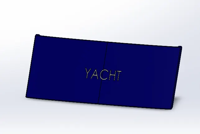
5.Garage door:
A Garage door is a large door on a garage that opens either manually or by an electric motor.It is used to accommodate automobiles and other vehicles.
Commands used
In Sketch
- Line
- Spline
- Circle
- Text
In Features
- Extruded cut
- Reference plane
- Fillet
- Shell
- Mirror
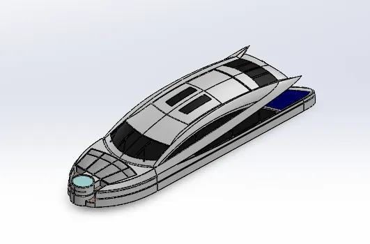
6.Superstructure
A Superstructure is an upward extension of an existing structure above a baseline called ground level .In ships,this is the name given to the part of the ship that emerges from the deck.
Commands used:
In Sketch
- 3D Sketch
- Line
- Spline
- Circle
- Rectangle
- Center point Arc
In Surfaces
As previously explained the definition of surfaces used in Hull part I just highlighted all the surfaces used in Superstructure part,
- Ruled surface
- Knit surface
- Trim surface
- Extend Surface
- Filled surface
- Lofted surface
- Revolved surface
- Fillet
- Chamfer
- Extruded surface
In Features
- Project curve
- Reference curve
- Convert entities:
Convert Entities enables you to copy model edges into your active sketch.
- Split
- Split line
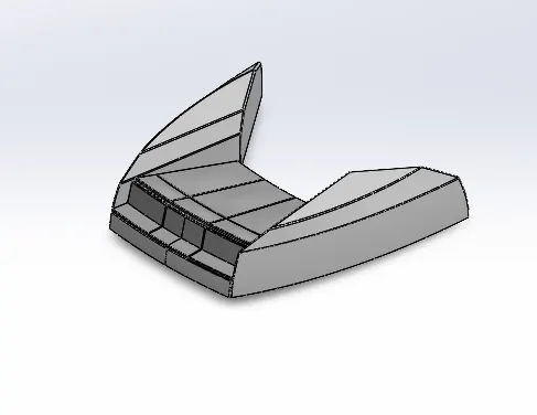
7.FRONT SEAT
The Front seat in our model was placed before the superstructure and also it has sun pads to rest on it.Lounge seats make it easier to kick feet up and get more comfortable.
Commands used:
In Sketch
- Sketch Picture
- Line
- Spline
- Circle
- Arcs
In Surfaces
- Extruded surface
- Lofted surface
- Trim surface
- Filled surface
- Knit surface
- Swept surface
- Revolved surface
In Features
- Extruded cut
- Revolved Boss/Base
- Chamfer
- Fillet
- Mirror
- Dome
8.MIDDLE SEAT
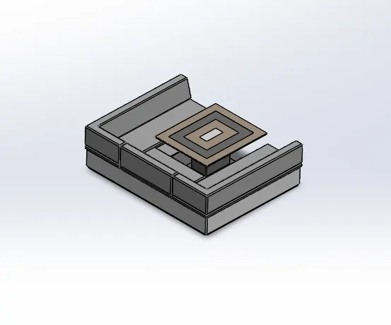
The middle seat in our model was placed just behind the superstructure.It is provided with a luxury table to dine out.It can also be used to have casual chatting with co-passengers.
Commands used
In Sketch
- Sketch Picture
- Line
- Rectangle
In Features
- Extruded Bose/Base
- Chamfer
- Fillet
- Mirror
- Reference Plane
9.REAR SEAT
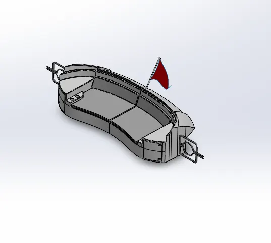
The rear seat was placed at the end of the deck surface.It consists of locker racks and steel doors.The flag was also placed behind the rear seat.The rear seat was also provided with a slots to rest the glass or mug.
Commands used:
In Sketch
- Sketch Picture
- Line
- Spline
- Circle
- Arcs
- Rectangle
In Surfaces
- Swept surface
- Extruded surface
- Offset surface
- Filled surface
- Knit surface
- Ruled surface
- Lofted surface
In Features
- Reference plane
- Extruded Boss/Base
- Revolved Boss/Base
- Fillet
- Mirror
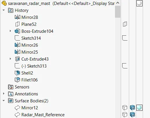
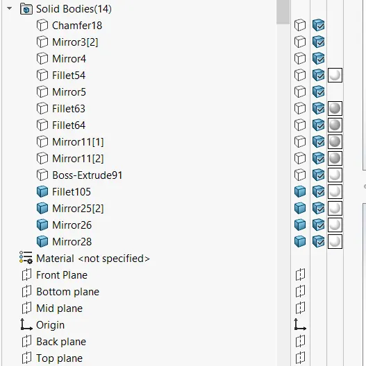
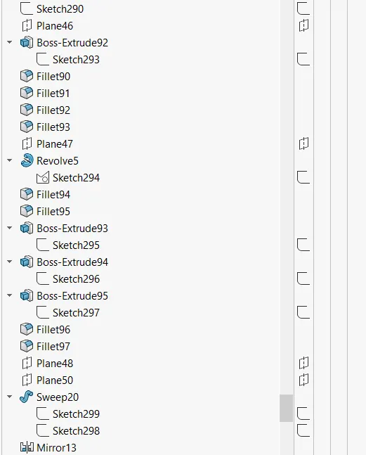
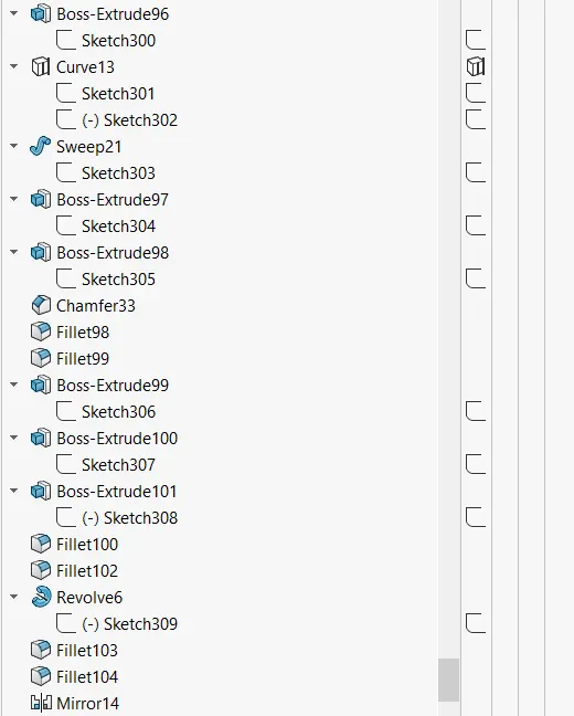
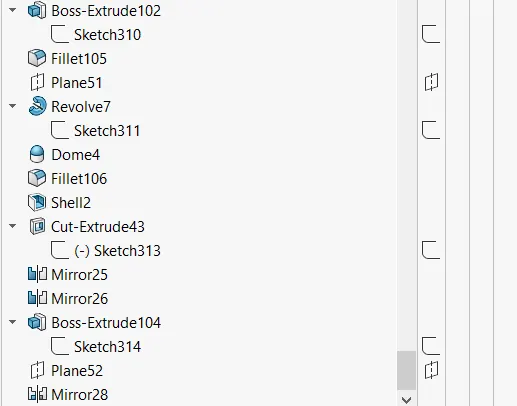
10.RADAR MAST:
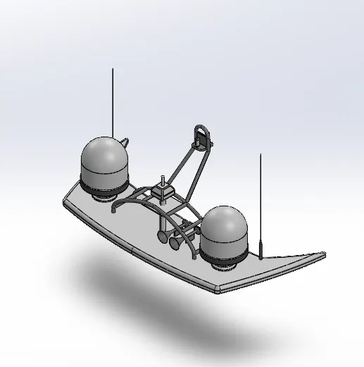
A mast is mounted on top of bridge and holds necessary equipments such as radars,Navigation light and ship horn .It is also used to hoist ships flag.
Commands used
In Sketch
- Sketch picture
- Line
- Spline
- Rectangle
- Arcs
In Feature
- Extruded Boss/Base
- Lofted Boss/Base
- Revolved Boss/Base
- Swept Boss/Base
- Reference Plane
- Fillet
- Mirror
- Dome
- Shell
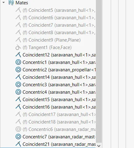
Assembly of the yacht:
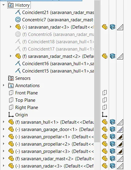
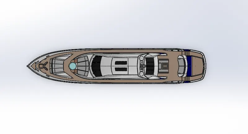
All the modelled parts were inserted one by one in the assembly.The first part that was inserted in the environment was hull.Since some parts like Superstructure,front seat,radar mast and middle seat were created by taking hull deck surface as a reference,they got automatically fixed over the hull while they were being inserted in the assembly environment.
The parts radar,garage door and propellers were not fully fixed since they need to have rotary motion.So these parts were given the mates maually to allow them to move along a particular axis only.
The rear seat was also given the manual mates so as to fix it just before the ending of the deck surface.
Isometric view
Front view
Left view
Top view
Camera setup view
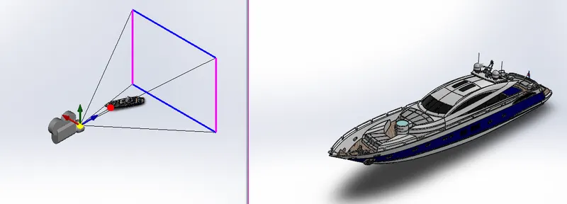
PHOTOREALISTIC RENDERING
Rendering is the process of creating realistic images of the model in an environment.Renders are obtained using Photoview 360 and Solidworks Visualize
Rendered images using Photoview 360
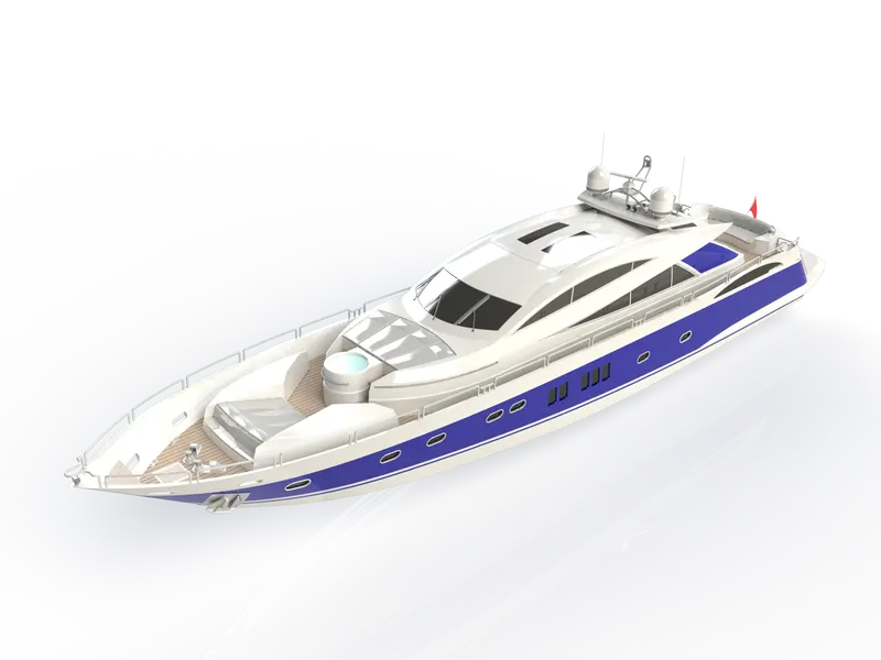
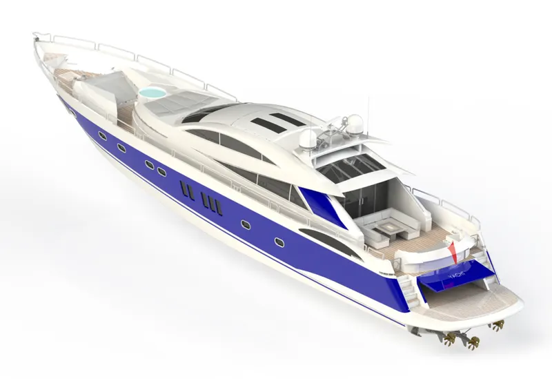
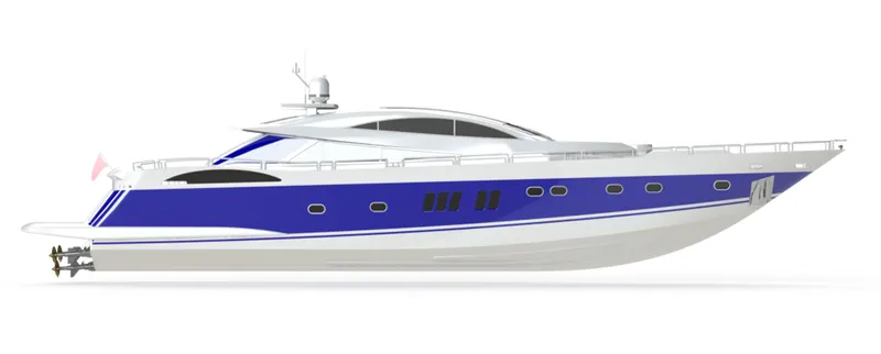
Rendered images using Solidwokds Visualize
Rendered image 1
Rendered image 2
Rendered image 3
Rendered image 4
CONCLUSION:
All the parts of the yacht were modelled and assembly was created using Solidworks and Photorealistic renders of the yacht were created using Photoview 360 and Solidworks Visualize.