Radar Mast & Final Assembly of Yacht
Design and Assembly of Yacht Model in Solid works
Objective:
The main objective of this project is to design the sunseeker yacht model in solid works and to explore the Surface workbench tools, Photo view 360, rendering options.
Introduction about yacht:
Yacht, a sail- or power-driven vessel, usually light and comparatively small, used for racing or for recreation. In recreation, the term applies to very large craft, originally powered by sail and later by steam or internal-combustion engines. It is in this sense that the generality of non-yachting (non-sailing) people usually thinks of the term. Technically, the word yacht excludes boats propelled by paddles, oars, or outboard motors. Also, recreational powered craft below the largest size are usually called cabin cruisers.
Design Methodology:
The Design Methodology of this project is like Reverse Engineering process. The components were designed by using the Blueprint sketches. The Bottom-up approach was carried out here by modelling the individual components of the Yacht and finally assembled together.
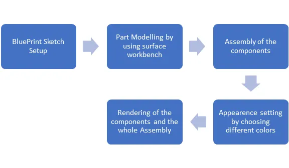
Modelling has been done by constraining the sketch, so that there won’t be any modification while doing assembly. Also, some of the dimensions were approximate, that is solved in the assembly workbench to get the proper mating and constrains.
Rendering the parts has been carried out in the final stage of the project. This gives good appearance to the bike and the back ground scenes were added to give aesthetic looks and feel of the Chopper.
Description:
Tools/ Features used while designing:
Part modelling features:
Extrude Boss: This is used to extrude the base sketch or selected sketch contour in one or two directions to create a solid feature.
Revolved Boss: This is used to revolve the base sketch or selected sketch contour around the axis to create a solid feature. The revolving degrees can be controlled here.
Swept Boss: This is used to sweep a closed profile along an open or closed path to create a solid feature.
Extruded Cut: This removes the material from the sketched profile in one or two directions. We can also add draft angle while removing the material.
Extrude Boss: This is used to extrude the base sketch or selected sketch contour in one or two directions to create a solid feature.
Revolved Boss: This is used to revolve the base sketch or selected sketch contour around the axis to create a solid feature. The revolving degrees can be controlled here.
Swept Boss: This is used to sweep a closed profile along an open or closed path to create a solid feature.
Boundary Boss: This feature adds the material between profiles in two directions to create a solid feature.
Extruded Cut: This removes the material from the sketched profile in one or two directions. We can also add draft angle while removing the material.
Revolved Cut: This cuts the solid model by revolving the sketched profile around the axis.
Swept cut: This cuts the solid model by sweeping a closed profile along the open or closed path.
Fillet: This is used to remove the sharp edges form the model by creating rounded faces in the internal or external edges.
Chamfer: The chamfer tool creates a beveled feature on selected edges, faces, or a vertex.
Linear Pattern: Pattern features, faces or bodies in one or two linear directions.
Circular Pattern: This is same like linear but the pattern occurs in the circular directions with angle.
Shell: This is used to hollows out a part by leaving the open faces which we are selecting and creating the thin-walled feature on the remaining faces. If we don’t select any of the faces, then it will create a closed hollow model.
Combine: Combine two or more single bodies. Also, we can combine the common intersection faces.
Split: Create multiple body from the single body.
Convert Entities: This is used to convert the selected edges or sketch entities into identical entities by projecting them onto the sketch plane or face.
Surface Modelling Features:
Extrude surface: This is used to Extrudes a sketch or selected sketch contours in one or two directions to create a surface feature. We can also control where the extrudes starts from, and define its direction and extends.
Revolve surface: It is used to revolves a sketch or selected sketch contours around an axis to create a surface feature. We can define the axis of revolution and the direction and the extend of revolved surface.
Lofted surface: It creates a lofted surface between two or more profile or sketches, by specifying the start and end constraints and also by adding guide curves to control the path shape.
Swept surface: It sweeps a closed profile along an open or closed path to create a surface feature. It also uses a tangent plane at the end of the path so that the path is normal to the swept surface. Also uses guide curve, profile orientations and twist angles to create different shapes.
Filled Surface: This feature Patches a surface within a boundary defined by edges, sketches or curves. It also uses constraint curves to fill surfaces and adjust the resolution controls to improves surface finish.
Boundary surface: It creates a surface between profiles that can be tangent or curvature continuous in all directions. In the graphics area use connectors or instant 3D drag handles to shape the boundary surface.
Offset surface: This is used to Offset the surfaces using one or more contiguous faces. The tools create an offset surfaces with gaps. We can repair the gaps manually or run the tool again and adjust the offset distance.
Ruled surface: It inserts ruled surfaces in a specified direction from the edges. Select tangent to surface, normal to surface, tapered to vector, or sweep. We can also trim and knit the surfaces and remove any connecting surfaces.
Extend surface: It extends one or more edges or faces on a surface, based on the end condition and extension type.
Trim surface: It is used to trim where the surfaces intersect with another surface, a plane or a sketch. We can select the trim type, trim tool and the surfaces to keep or remove. We can also change how the trim boundaries extend from end points to the trim tool.
Thicken: It creates a solid feature by thickening one or more adjacent surfaces. If we want to thicken multiple adjacent surfaces, knit the surfaces together before thicken the surfaces.
Knit Surface: This is used to combine the two or more adjacent, non-intersecting surfaces into a single surface body. The surface must join at an edge.
Design of Propeller:
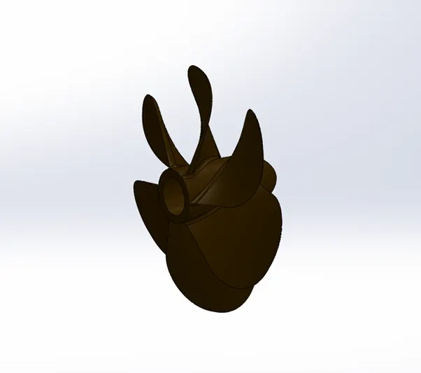
Propeller is the Mechanical component which is used for power delivery from the engine. This helps the yacht to move forward with the help of rotation motion, thus by producing the thrust needed for the movement.
- The design of propeller is done by using the features like Revolve, Loft, Cut Extrude, Fillet and Circular pattern
Design of Radar:
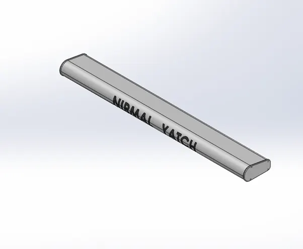
Marine radars are X band or S band radars on ships, used to detect other ships and land obstacles, to provide bearing and distance for collision avoidance and navigation at sea. They are electronic navigation instruments that use a rotating antenna to sweep a narrow beam of microwaves around the water surface surrounding the ship to the horizon, detecting targets by microwaves reflected from them, generating a picture of the ship's surroundings on a display screen.
- The design of Radar was done by using the features like Boss Extrude, Cut Extrude, Fillet, Sketch pattern, Mirror and Split line
Design of Hull:
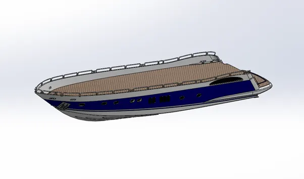
"V-shaped" hulls are planning hulls, and are the most common type of hull for powerboats. Deep V-shaped boats are designed to plane on top of the water at higher speeds and provide a smoother ride through choppy water. These boats are usually equipped with a larger engine than flat or round-bottomed boats.
- The Hull design was done with features like Project Curve, surface Loft, Surface Trim, Surface Extrude, Surface Fill, Surface Knit, Shell, Boss Extrude, Cut extrude, Fillet, Chamfer, Plane creation, Sweep, Revolve, Dome, Helix, Linear Pattern, Delete Face, 3D sketch, Mirror, Split Line, Surface offset.
Front Seat:
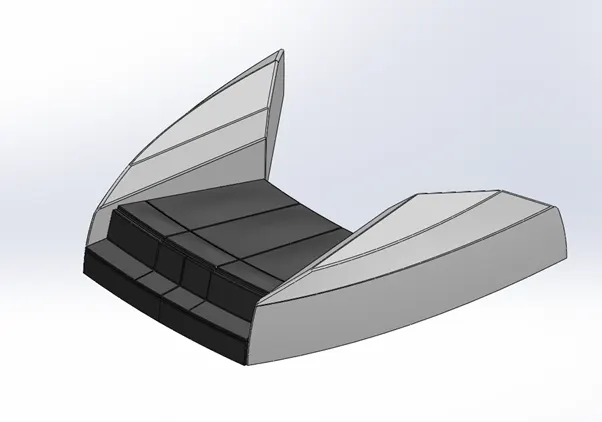
The front seat in the yacht gives the overall front view of the sea while sailing. This seat was designed in such a way that it can accommodate around 8 peoples. The surface finish of this seat was done with Matte rubber finish feel and look. This adds more aesthetic looks to the yacht.
- The features used in this front seat design were as follows; Sketch, surface sweep, surface extrude, surface trim, surface fill, dome, surface Loft, surface knit, chamfer, revolve, cut extrude, fillet and Mirror.
Middle Seat:
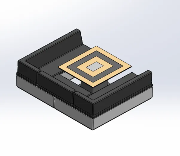
The Middle seat in the yacht gives the side view and back view of the sea while sailing. This seat was designed in such a way that it can accommodate around 12 peoples. Also, a dining table was designed and placed for this seat. The surface finish for the table is like mirror finish with gold plating colour. The surface finish of this seat was done with Matte rubber finish feel and look. This adds more aesthetic looks to the yacht.
- The features used in this front seat design were as follows; Boss extrude, chamfer, cut extrude, fillet and Mirror.
Rear Seat:
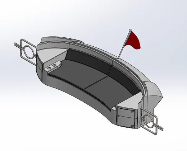
The Rear seat in the yacht gives the overall rear view of the sea while sailing. This seat was designed in such a way that it can accommodate around 8 peoples. Also, this can be used as a sophisticated couch with bottle holders in the sides. The Red Flag hoisted at the back of this seat gives a premium look and feel. The Rails on the both sides give protection to the passengers. The storage cabin under this seat can be used for multiple purpose. The surface finish of this seat was done with Matte rubber finish feel and look.
- The features used in this front seat design were as follows; Sketch, surface sweep, surface offset, surface trim, ruled surface, surface extrude, surface extend, Boss extrude, sweep, surface Loft, surface knit, chamfer, revolve, cut extrude, fillet and Mirror.
Superstructure:
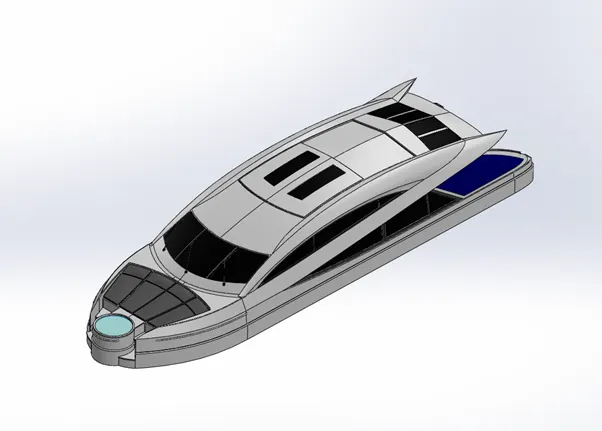
Traditionally, a cruising yacht’s superstructure has been built using metallic materials such as steel or aluminium. Superstructures built using steel are heavy, need excessive maintenance and have limitations when building smooth shapes. Aluminium superstructures are lighter and need less maintenance, but still have limitations in building smooth shapes. In addition, aluminium superstructures are more expensive than steel ones. This design is the use of fiberglass laminate composite as a material for superstructure construction and exemplifies the methodology used in the design stage and construction of cruising yacht with a steel hull. The methodology includes
- Scantling of structural steel elements and fiberglass panels used for composite lamination.
- Laminating procedure for the elements used for reinforcement to avoid deterioration of the steel structure.
- Fire resistance recommendations for the composite laminate. The advantages of composite laminate are: structural weight reduction, fuel consumption reduction, apparent increase of wind area, superstructure maintenance cost reduction, and inert behaviour with the steel structure that avoids galvanic corrosion.
- The features used in this superstructure design were as follows; Sketch, surface sweep, surface offset, surface trim, ruled surface, surface extrude, surface extend, surface fill, projected curve, ruled surface, delete face, Boss extrude, cut extrude, sweep, surface Loft, surface knit, chamfer, revolve, cut extrude, Thicken, Dome, Split Line, Combine, fillet and Mirror.
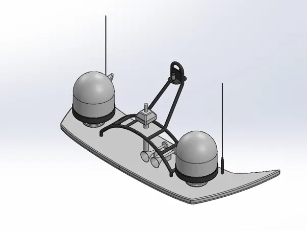
Radar Mast:
A mandatory aid to navigation, the radar is used in identifying, tracking (with integrated ARPA) and positioning of vessels (including one’s own vessel) among other things in order to adhere to the COLREGs so as to safely navigate the ship from one point to another.
- The features used in this Radar mast design were as follows, Boss extrude, sweep, surface knit, chamfer, revolve, cut extrude, dome, combine, fillet and Mirror.
Garage Door:
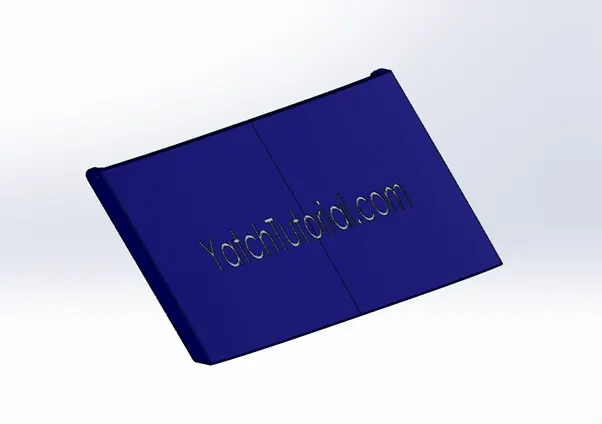
The garage door was designed to close the garage area. This is done with the hinged design, so that door can be easily lift and close. The American chopper model bike is placed in the garage area.
- The features used for this design are as follows; Cut extrude, shell, Mirror, Fillet, Plane creation.
Final Assembly:
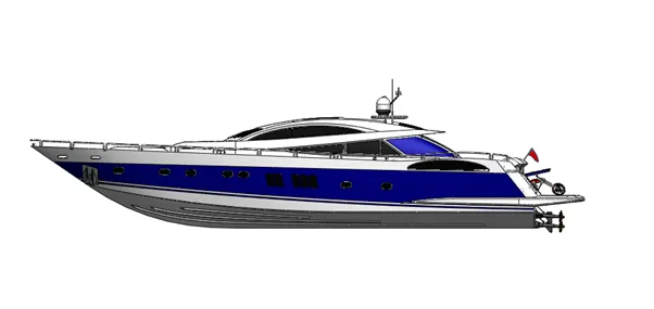
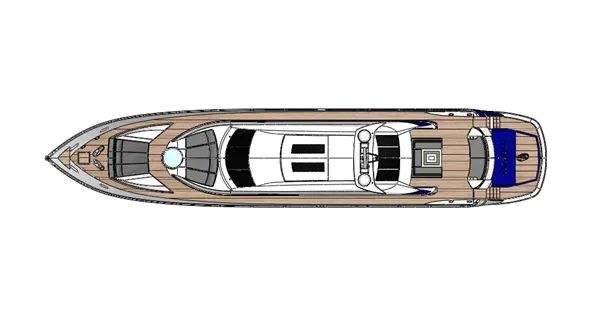
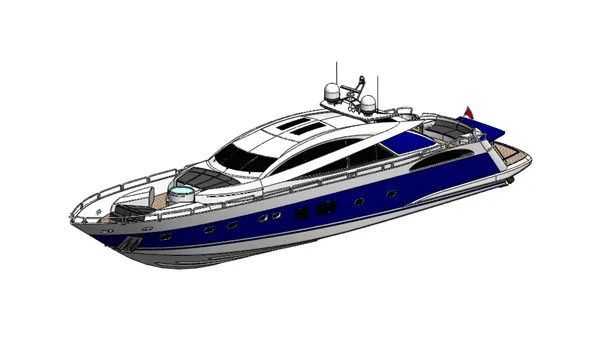
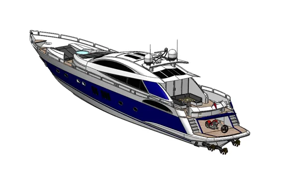
The final assembly of the yacht is completed by using Assembly workbench, where the individual parts are assembled together by mating and constraints.
All the components are fixed in their position as per the design. This assembly is then processed for Rendering for the final look and feel of the yacht.
Views of the Assembly:
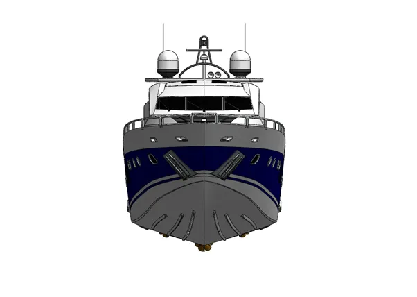
Front view:
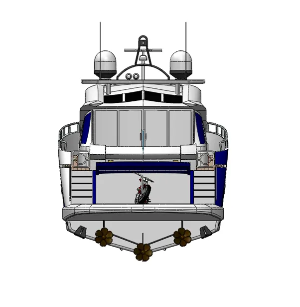
Back view:
Side view:
Top view:
Isometric view:
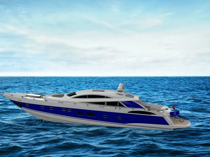
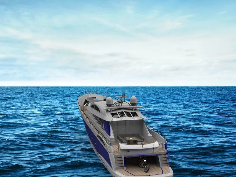
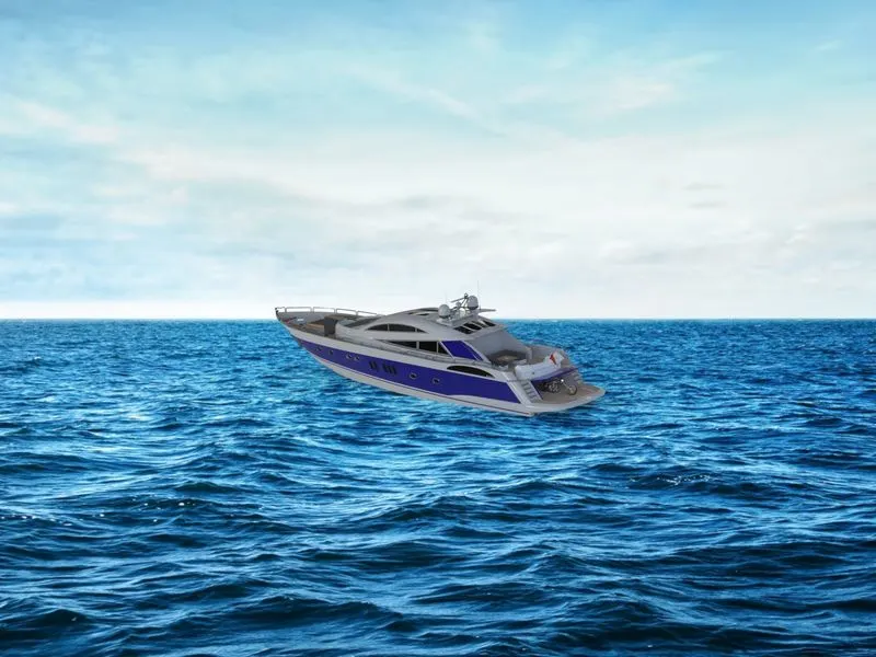
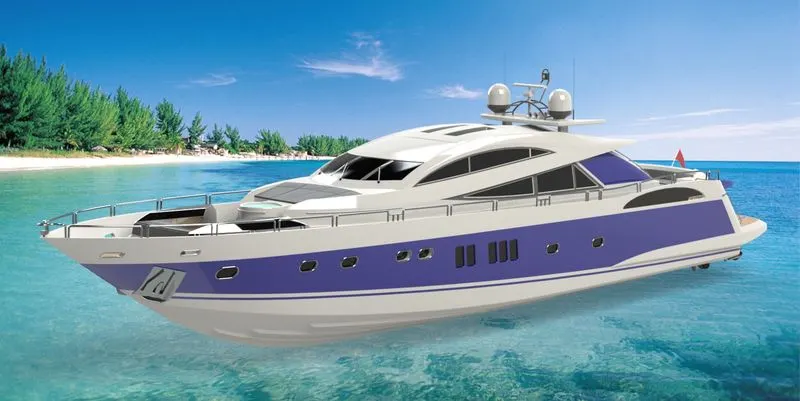
Rendering:
- Rendering is the additional feature which gives the actual look and feel of the bike model.
- This is done by adding different materials to the different components like Rubber to the tyre, chrome look to the Engine and chassis.
- These can be done by using Photo view 360 add-ins.
- Solid works Visualize is used for the final rendering with custom background options.
Rendered Images:
Conclusion:
Thus the Design and Aseembly of yacht was completed sucessfully in Solid works software using part modelling and surface modeeling workbech. Also Rendering completed using Solid works Photo view 360 and Visualize addin.