Project - Speed Control of a Direct Current (DC) motor
Q-1)Obtain the transfer function of a mass spring damper system and use it in the model. Add a PID controller to adjust the force on mass so that its position follows a reference signal.
Take m = 3.6; %kg k = 400; %N/m c = 100; %Ns/m
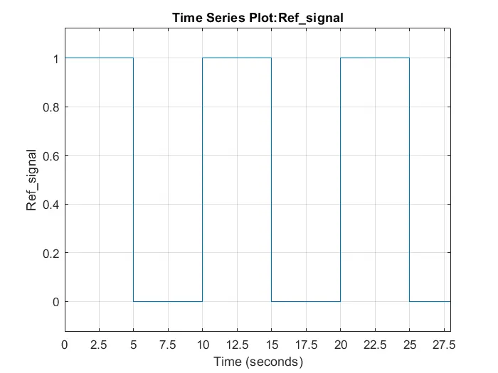
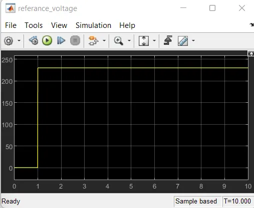
The reference signal is shown in the following figure.
Obtain the transfer function of a mass spring damper system and use it in the model. Add a PID controller to adjust the force on mass so that its position follows a reference signal.
Take m = 3.6; %kg k = 400; %N/m c = 100; %Ns/m
The reference signal is shown in the following figure.
Sol:-
M-Scripts:
%this file contain design parameter for DC motor.
j=0.01;% Moment of inertia of the rotor in (kgm^2).
b=0.1;% momentof viscous friction constant in (Nms).
km=0.01;% Back EMF.
kt=0.01;% Motor Torque.
Ra=1.0;% Resistance of armature circuits (ohm).
La=0.5;% inductance of armature circuit (henries).
%this file contain design parameter for DC motor.
j=0.01;% Moment of inertia of the rotor in (kgm^2).
b=0.1;% momentof viscous friction constant in (Nms).
km=0.01;% Back EMF.
kt=0.01;% Motor Torque.
Ra=1.0;% Resistance of armature circuits (ohm).
La=0.5;% inductance of armature circuit (henries).
%% Design of PID controller.
A=[-b/j kt/j;-km/La -Ra/La];
B=[0;1/La];
%% placement of poles.
fn=1;
wn=2*pi*fn;
zeta=0.5;
p1=-zeta*wn+wn*sqrt(zeta^2-1);
p2=-zeta*wn-wn*sqrt(zeta^2-1);
P=[p1;p2];
k=place(A,B,P);
kp=k(1);
kd=k(2);
ki=0.0;
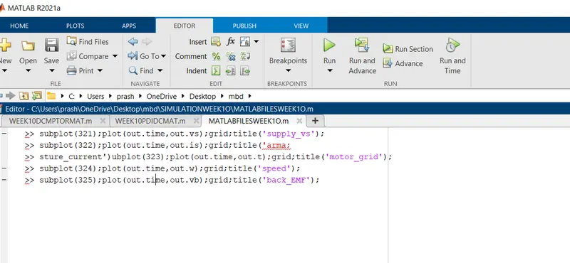
To PLot:
>> subplot(321);plot(out.time,out.vs);grid;title('supply_vs');
>> subplot(322);plot(out.time,out.is);grid;title('arma;
>> sture_current')ubplot(323);plot(out.time,out.t);grid;title('motor_grid');
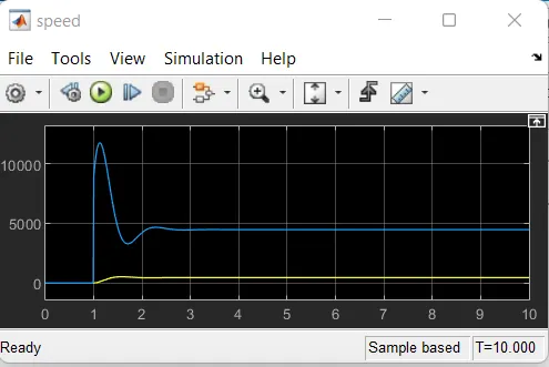
>> subplot(324);plot(out.time,out.w);grid;title('speed');
>> subplot(325);plot(out.time,out.vb);grid;title('back_EMF');
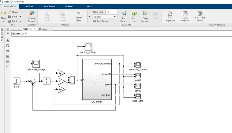
Simulink Model:
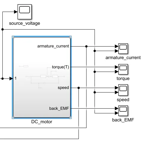
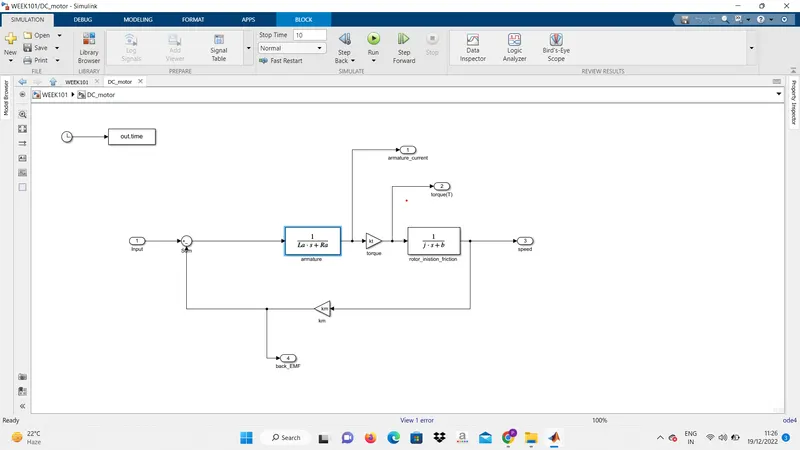
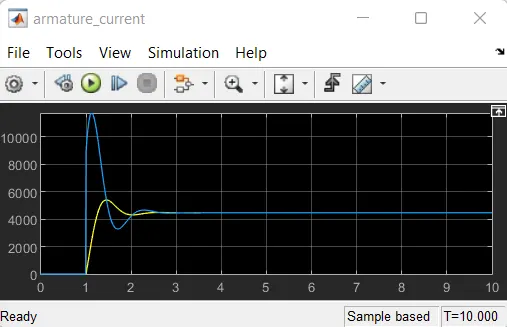
Scope:Armature Current
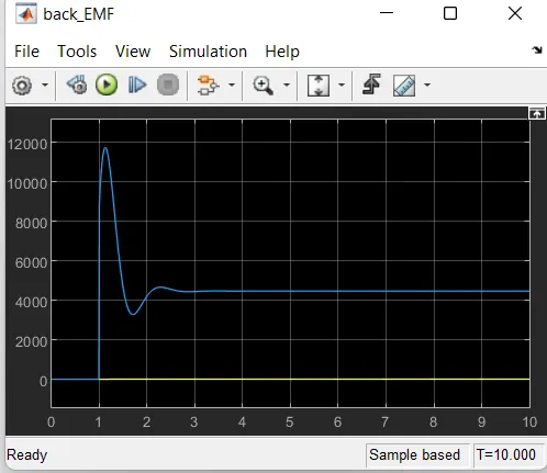
Scope:BACK emf
Scope:Reference Vtg
Scope:Speed
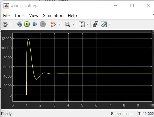
Scope:Source Vtg
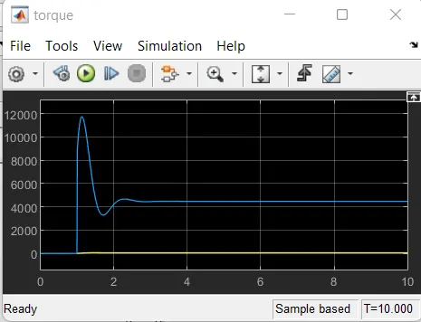
Scope:Torque