Project - Speed Control of a Direct Current (DC) motor
Project - Speed Control of a Direct Current (DC) motor : -
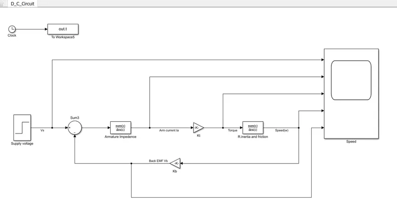
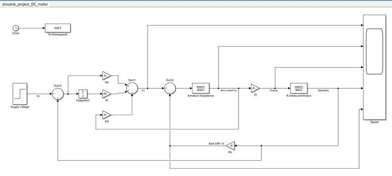
In this project, a Simulink model for the DC motor will be first developed per the schematic shown in Figure 1.
Use the Proportional, Integral, and Derivative (PID) control design knowledge gained in the training to design, develop and test a controller to maintain a desired speed for the motor.
ANSWER : -
- Speed Control of a Direct Current (DC) motor : -
Here the Speed control of a DC motor is either done manually by the operator or by means of an automatic control device. so the speed can be varied by changing:
The terminal voltage of the armature V.
- What do you mean by speed control of motor?
Jan. 1, 2008. Speed, torque, and horsepower are three inter-related parameters in motor control.
The speed of a motor, measured in revolutions per minute (rpm), defines a motor's ability to spin at a rate per unit time.
- What is speed control called?
Cruise control (also known as speed control, cruise command, autocruise, or tempomat) is a system that automatically controls the speed of a motor vehicle.
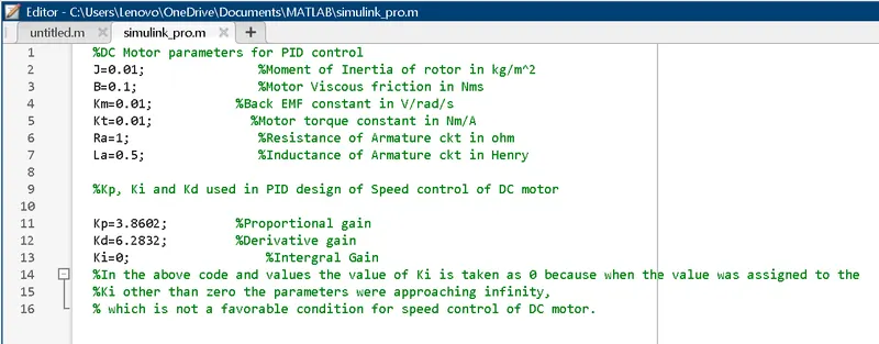
MATLAB CODE : -
Below is the Model of the DC motor according to the circuit shown above.
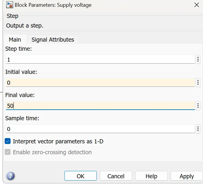
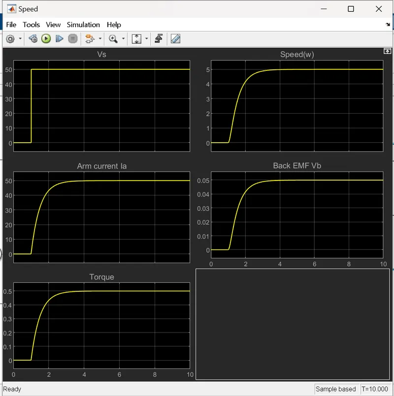
Below is the Model for the PID controller for the speed control of the DC motor.
MATLAB CODE :-
In this model the PID controllers are added with the values shown above.
Here we consider the PID control paramters as :
Kp =3.8602,
ki =80,
kd =6.2832
Settling time <2sec
Overshoot<5%
Steady-state error<1%
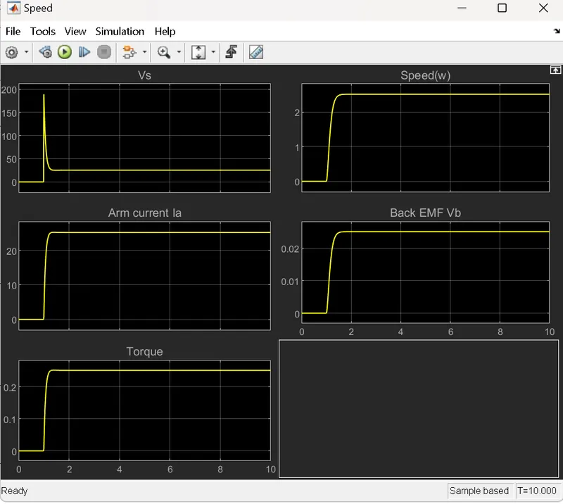
These parameters can be considered that it will keep the system in a stable state as fast as possible.
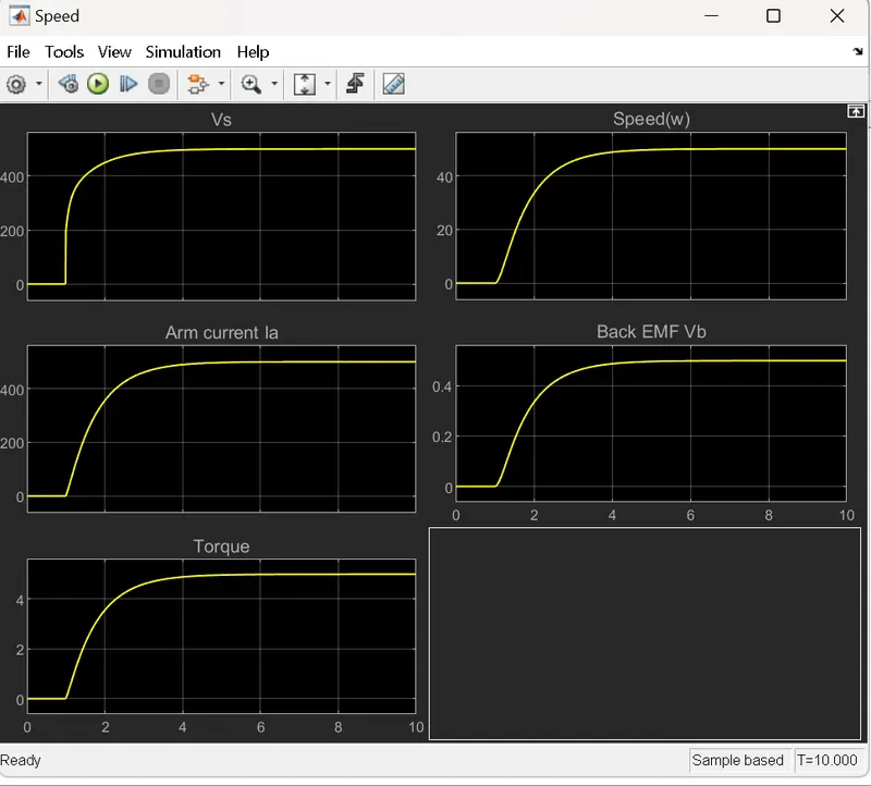
In the case shown below the value of Ki is kept as 80 which results in a ramp-like output that approaches infinity and hence the system doesn't achieve stability.
GRAPH FOR PID CONTROLLEDR FOR THE SPEED CONTROL OF DC MOTOR : -
I have used the tools to construct the these models:
Clock : output the current simulation time.
Constant : Output the constant input value.
Step : Output a step.
Integrator : Continous time integration of input signal.
Sum : Add or subtract the inputs.
Add : Add or subtract the inputs.
Scope : Display input signals with respect to the simulation time.
Gain : The Gain block multiplies the input by a constant value (gain).
Integral : The Integrator block outputs the value of the integral of its input signal with respect to time.
To Workspace : The To Workspace block logs the data connected to its input port to a workspace from a Simulink model.
Transfer fcn : It gives the numerator and denominator values.
Summary:
Initially, the DC motor model was made and the values for PID design were calculated and the PID model was incorporated into the DC motor model.