Project - Speed Control of a Direct Current (DC) motor
Aim of the project-
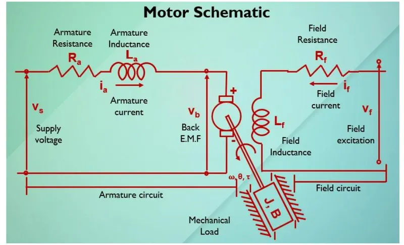
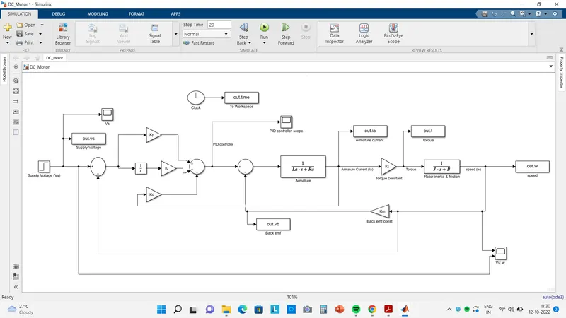
In this project, a Simulink model for the DC motor will be first developed per the schematic shown in Figure 1.
Use the Proportional, Integral, and Derivative (PID) control design knowledge gained in the training to design, develop and test a controller to maintain a desired speed for the motor.
Theory-
- Here the Speed control of a DC motor is either done manually by the operator or by means of an automatic control device.
- This is different to speed regulation where the speed is trying to be maintained or regulated against the natural change in speed due to a change in the load on the shaft
-
so the speed can be varied by changing:
- The terminal voltage of the armature V
- The external resistance in armature circuit Ra
- The flux per pole
-
So Terminal voltage and external resistance involve a change that affects the armature circuit while flux involves a change in the maginetic field
-
so Therefore speed control of DC motor can be classified into:
- Armature Control Methods
- Field Control Methods
In this Project we used the Armature control method for the speed control of DC motor.
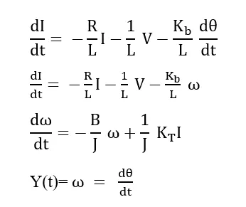
The mathematical modelling of DC motor is,
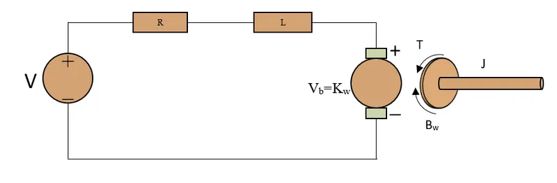
The DC motor Parameters are,
J = Moment of Inertia of Rotor (kgm^2)
B = Damping Constant (Nms)
Ra = Armature resistance (ohm)
La = Armature inductance (Henry)
Vb = Back emf constant (volt)
Kt = Motor Torque constant (Nm/Amp)
V = Voltage (volt)
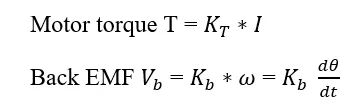
Step to find Equation
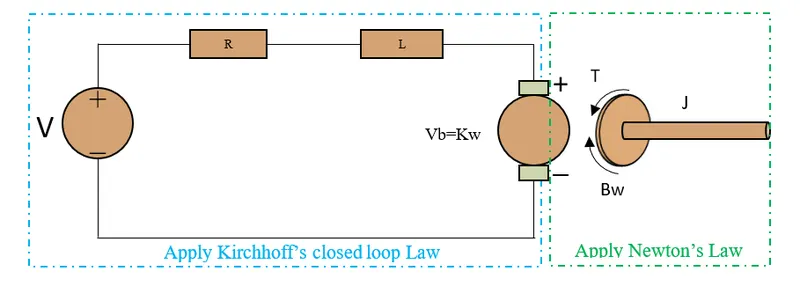
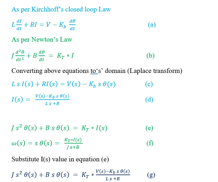
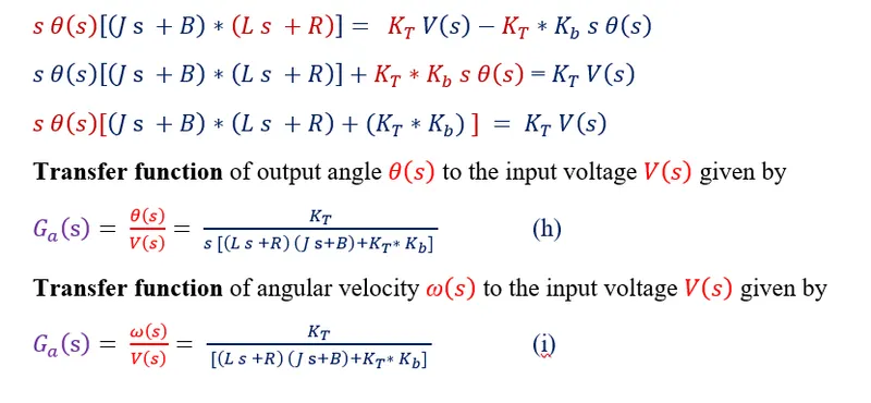
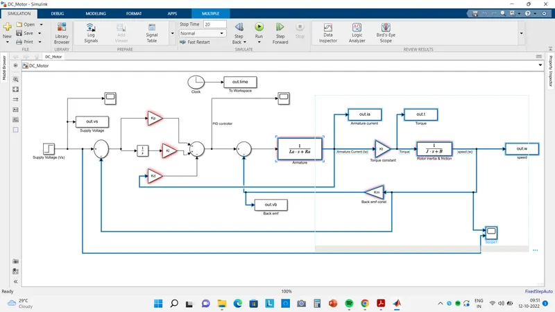
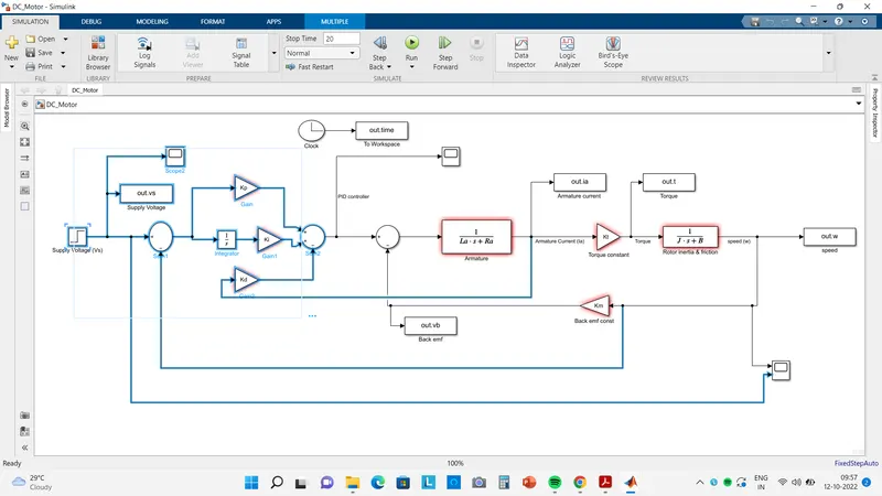
Modelling of Dc motor Shows in below Figure.
Blue highlighted portion in below model shows DC motor.
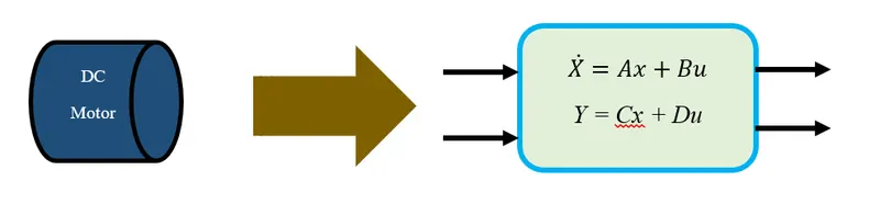
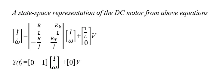
State-Space Equations for the DC Motor
State equations will now be derived by using equations (a) and (b)
Modelling of PID controller Shows in below Figure.
Blue highlighted portion in below model shows PID controller.
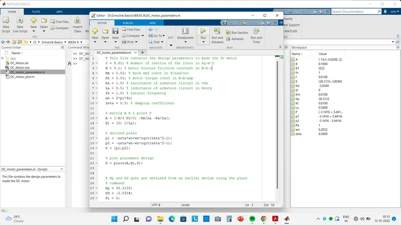
The M-script file for finding the value of Kd & Kp i.e. pole placement.
% This file contains the design parameters to made the DC motor
J = 0.01; % moment of inertia of the rotor in kg-m^2
B = 0.1; % motor viscous friction constant in N-m-s
Km = 0.01; % Back emf const in V/rad/sec
Kt = 0.01; % motor torque const in N-m/amp
Ra = 1.0; % resistance of armature circuit in ohm
La = 0.5; % inductance of armature circuit in Henry
fn = 1.0; % natural frequency
wn = 2*pi*fn;
zeta = 0.5; % damping coefficient
% matrix A B & poles P
A = [-B/J Kt/J; -Km/La -Ra/La];
B1 = [0; 1/La];
% desired poles
p1 = -zeta*wn+wn*sqrt(zeta^2-1);
p2 = -zeta*wn-wn*sqrt(zeta^2-1);
P = [p1;p2];
% pole placement design
K = place(A,B1,P);
% Kp and Kd gain are obtained from an earlier design using the place command
Kp = 38.3133;
Kd = -2.8584;
Ki = 0;
By writing this parameters in the script & run it to save in workspace which automatically pick by simulink model.
Whole Simulink Model-
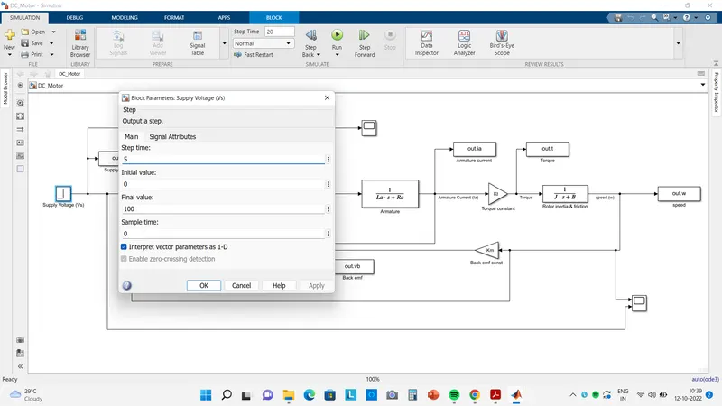
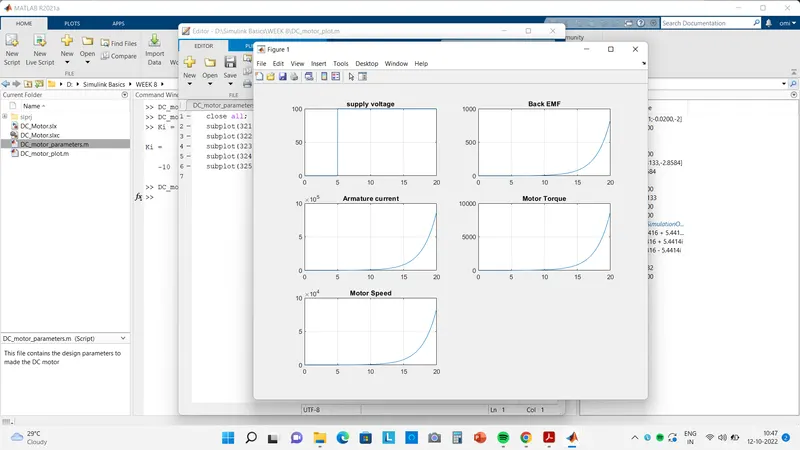
Run the simulation for 20 sec & step input of magnitude 100 with 5 sec step time.
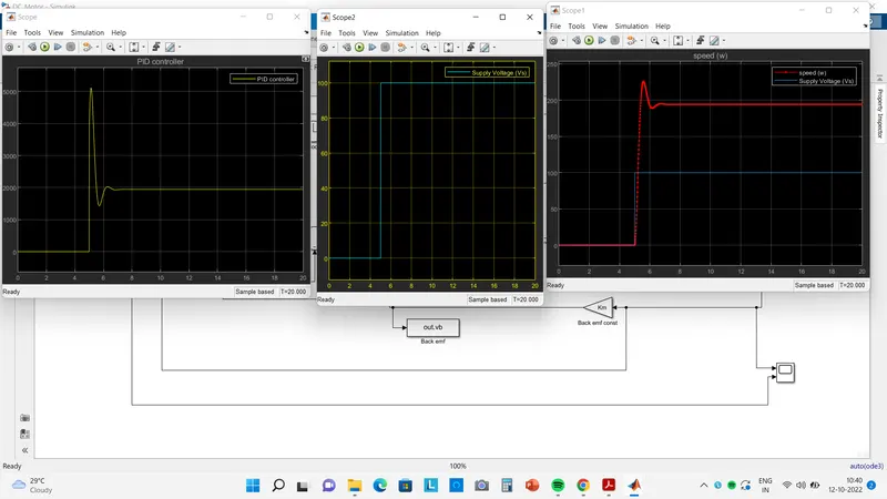
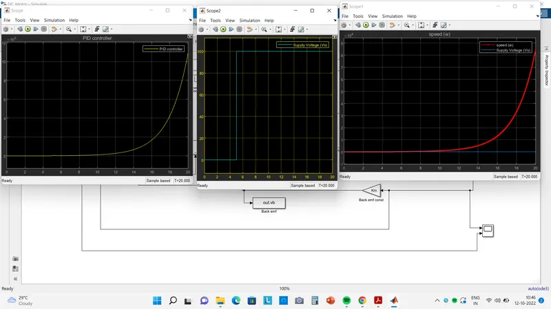
From the above response see that there is huge difference between Desired response and actual response,
So we need to choose the proper values of Kp, Kd, KI gain to met the controlled objectives like settling time, overshoot, steady state error.
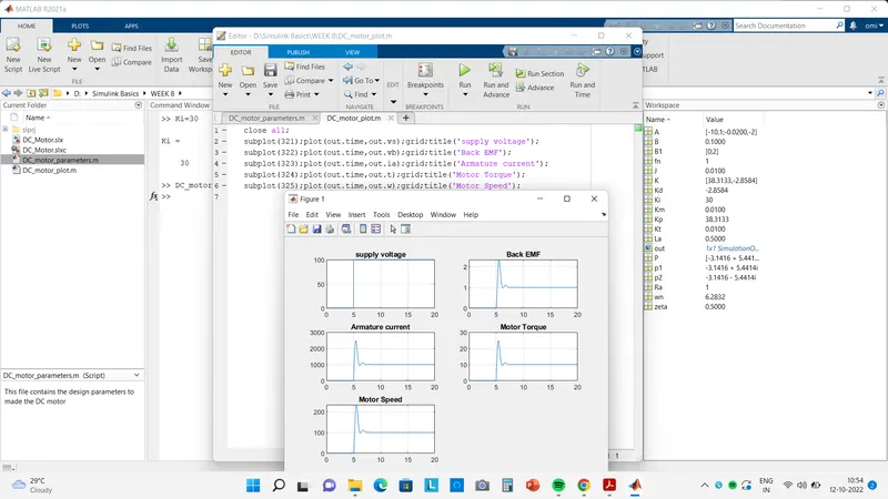
Now we increased & decreased the value of Ki & check the result to met the controlled objectives.
For steady state error reduction Ki value should change.
Kp = 38.3133; Kd = -2.8584; Ki = -10;
Kp = 38.3133; Kd = -2.8584; Ki = 10;
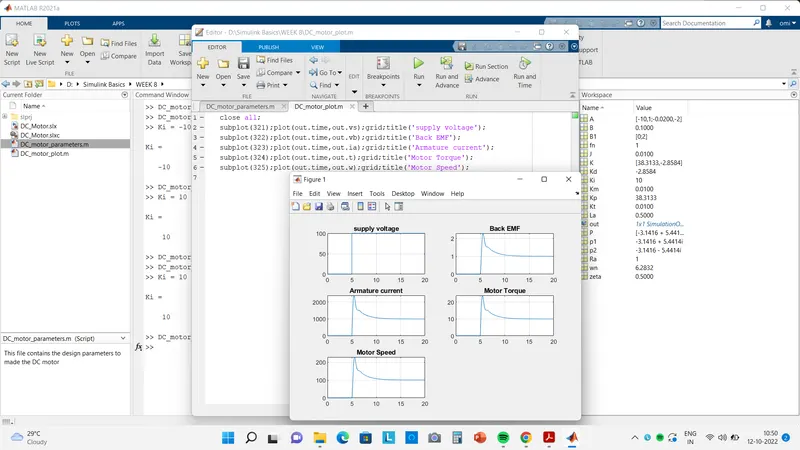
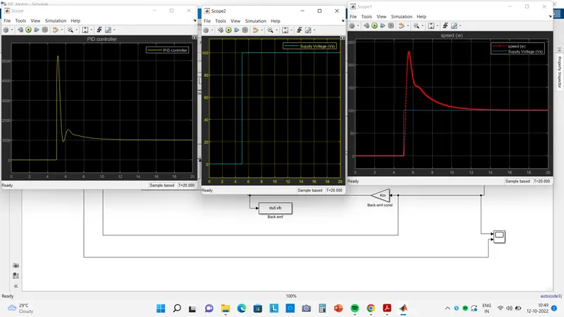
Comapre with Ki = 0 value the steady state erro is reducing but not met to desired value.
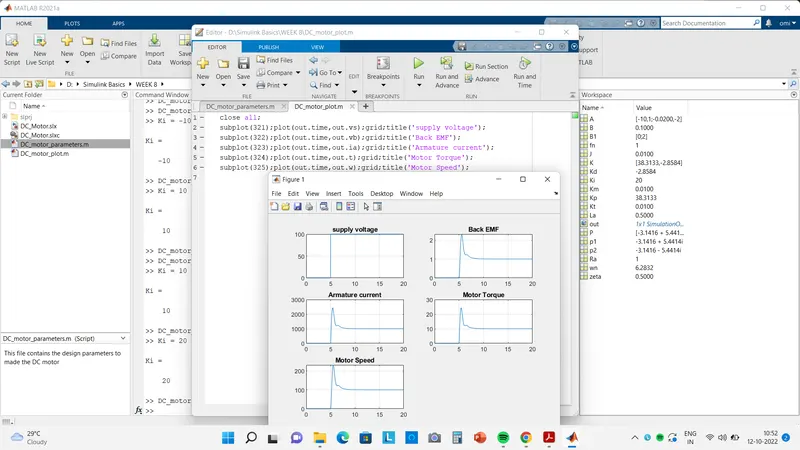
Kp = 38.3133; Kd = -2.8584; Ki = 20;
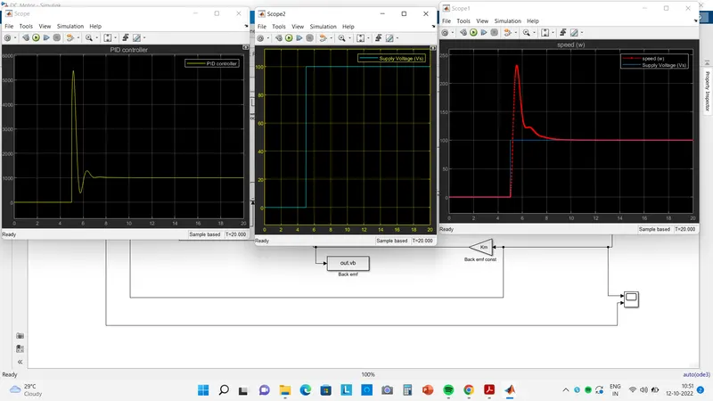
Kp = 38.3133; Kd = -2.8584; Ki = 30;
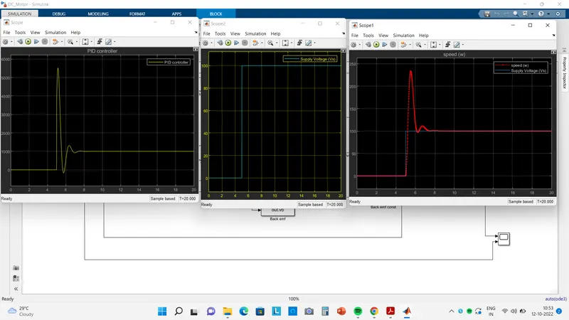
Kp = 38.3133; Kd = -2.8584; Ki = 35;
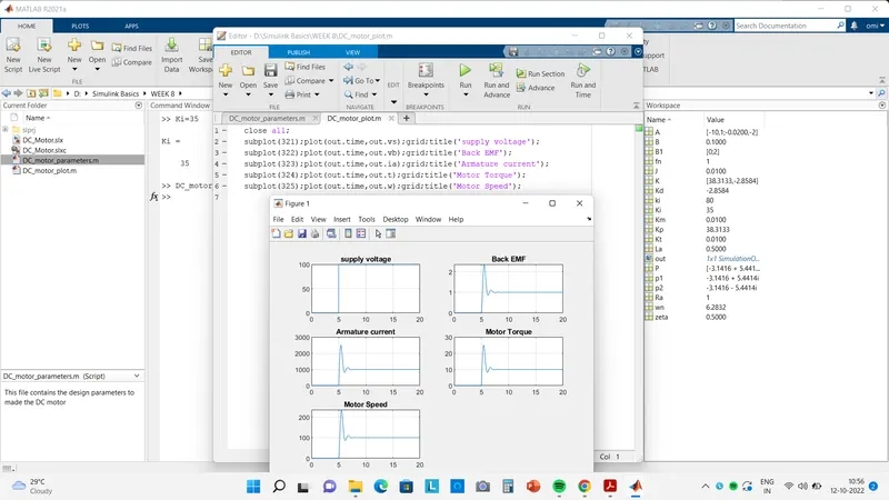
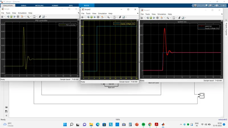
There is reduced in Steady state error but there is large overshoot in response.
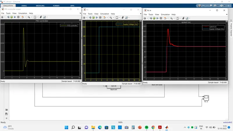
So the Overshoot can reduced by Kd gain
Kp = 38.3133; Kd = -2; Ki = 35;
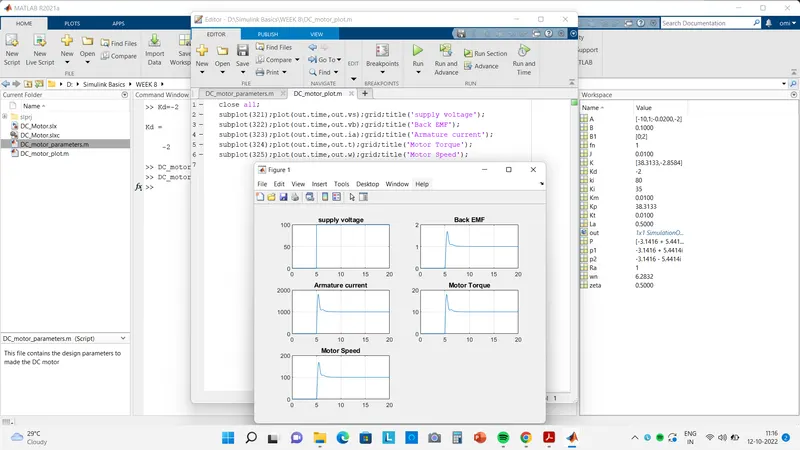
Kp = 38.3133; Kd = -1.5; Ki = 35;
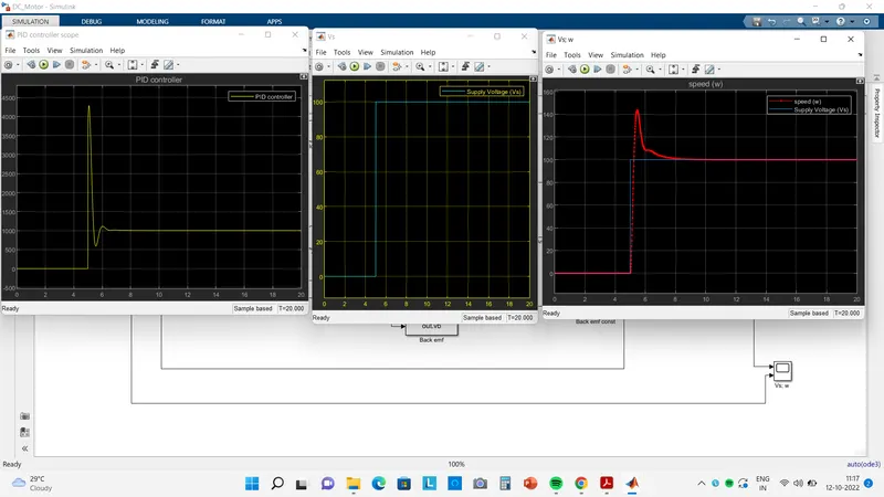
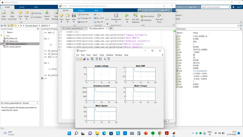
Kp = 38.3133; Kd = -0.4; Ki = 35;
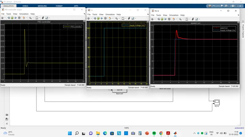
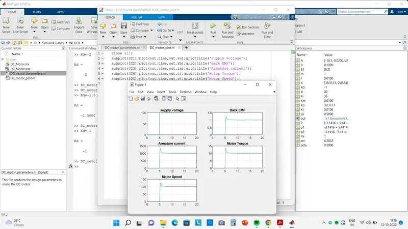
Kp = 38.3133; Kd = -0.4; Ki = 35;
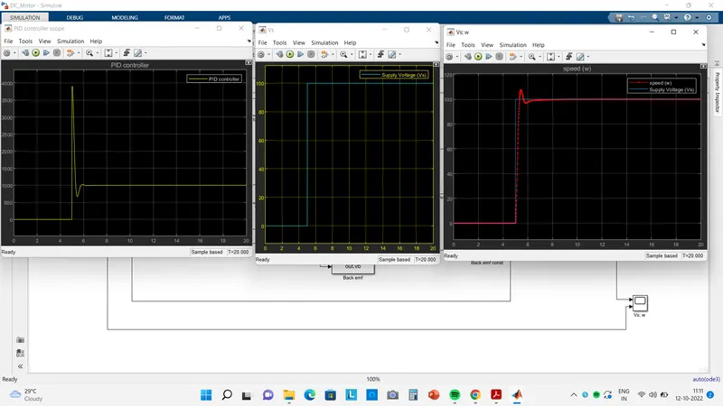
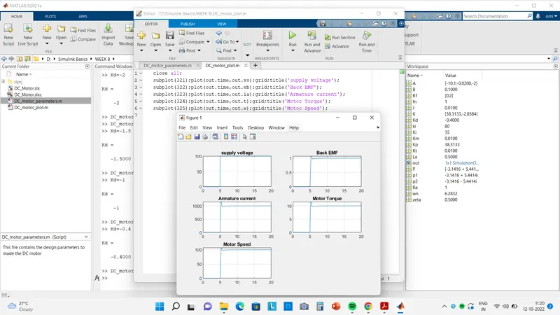
from the above values of Kd,Ki & Kp the most suitable values who gives the better response is
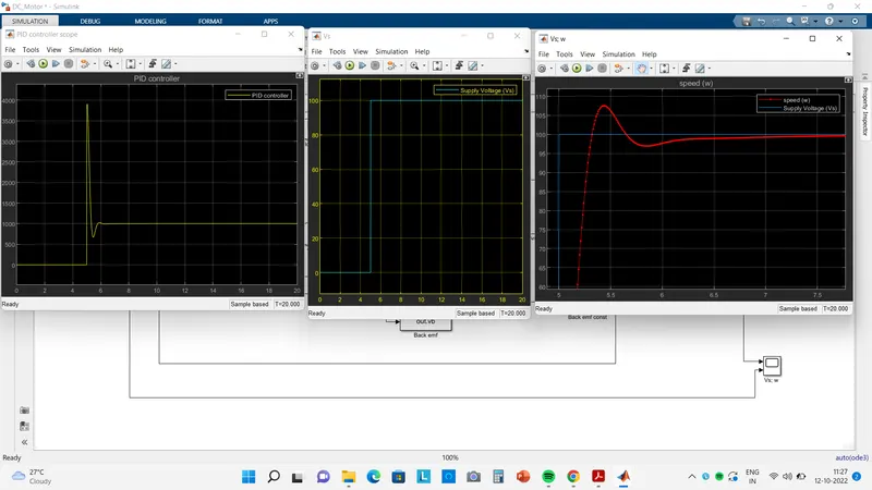
Kp = 38.3133; Kd = -0.4; Ki = 35;
Now we can change the input voltage & check the result.
Supply voltage= 230 V with 5sec step time
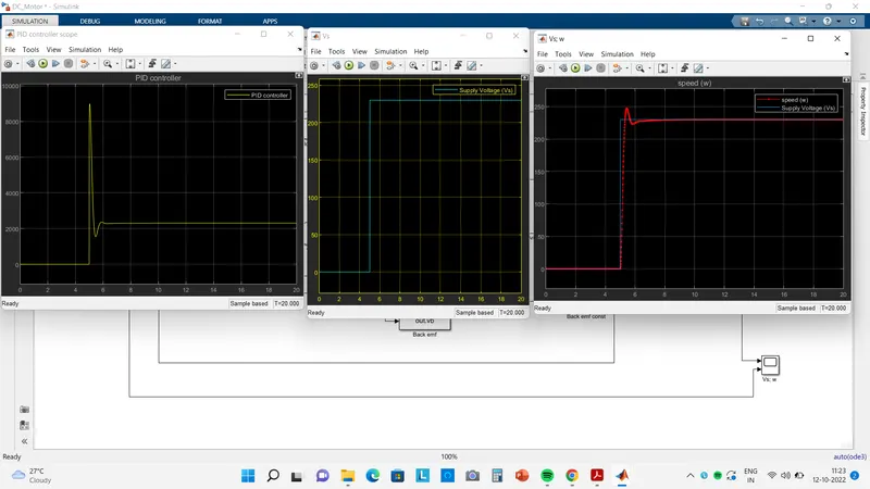
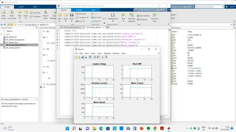
We can control the speed of DC motor by using the PID controller block which is availabe in simulink library also.
Conclusion-
The PID controller block manages the control objectives i.e.
Settling time < 2 sec
Overshoot < 5 %
Steady state error < 1 %.
we have desined In this project a Simulink model for the DC motor as shown in Figure(whole simulink model) and also we Use the Proportional Integral and Derivative PID control design knowledge gained in the training to design develop and test a controller to maintain a desired speed for the motor.