Project - Analysis of a practical automotive wiring circuit
Brief Study of the given Automotive Wiring Circuit:
This Automotive Wiring Circuit consists of various elements such as starter, battery, ignition coil, circuit breaker, distributor, generator, current and voltage regulator, foot selector switch, ammeter, fuse, gas tank unit, ignition switch, light switch, sealed beam lights, horns and lamps.
At first when the ignition switch is turned on, the starter starts the engine which is connected to the battery. The ignition coil is connected to the distributor and circuit breaker. The ignited current from the transformer is given to the distributor to ignite various plugs which are connected to the distributor.
Generator connected to the current and voltage regulator, they monitors the regulation of current and voltage. Generator charges the battery and runs the vehicle entire electrical system. The foot selector switch is connected with sealed beam bulbs which controls on and off. The dome light switch and stop light switch are connected with the dome lights and stop lights. Fuse is connected with all the light switches to protect the short circuit or overcurrent.
Gas tank unit is connected with the fuel gauge, in order to indicate the level of fuel. Ammeter is connected with the battery to measure the current. Both the Ammeter and battery then gas tank unit and fuel gauge are connected in series with each other. Horns are connected in parallel with horn buttons.
1. Major elements in the automotive wiring diagram are:
- Battery
- Starter
- Ignition coil
- Distributor
- Circuit Breaker
- Generator
- Current and Voltage Regulator
- Foot selector switch
- Ammeter
- Ignition switch
- Fuse
- Light switch
- Gas tank unit
- Lamps
- Horns
- Beams
2. Purpose and Working of any three elements:
(i) Starter:
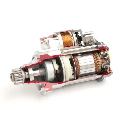
A Starter or Starter motor is an electrical device which is used to rotate internal combustion(IC) engines to initiate the engine's operation. When the engine commence to run, the starter gets disconnected from the engine and then it will rely on the combustion process.
Working:
Firstly, a battery is required to run the starter with enough power. Starter has a powerful DC motor and a solenoid. The solenoid receives power directly from the battery and it gets activated. When the ignition switch turn on, an electromagnet inside the body engages and pushed out a rod in which pinion gear is attached then pinion gear will mesh with flywheel, which is mounted on the engine crankshaft. As the engine begins to run by sucking the air in. Then the stater motor disengages from the flywheel and the rod retracts into the motor to prevent any potential damage.
(ii) Generator:
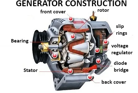
A Generator converts Mechanical energy into electrical energy. It gives power to the entire system when the engine gets started. The battery will be recharged automatically.
Working:
Generator has a series of insulated wire coils forms a stationary cylinder called as stator, then it is surrounded by an electromagnetic shaft called as rotor. When the engine crankshaft rotates, then the rotor starts to rotate and this will create a rotating magnetic field. The rotor generates an Alternating current and it reaches a required amount of speed, the excitation winding will generate the power and the AC flows through the diode bridge. The voltage regulator monitors the rotor operation. This current is given to the battery and with required voltage.
(iii) Circuit Breaker:
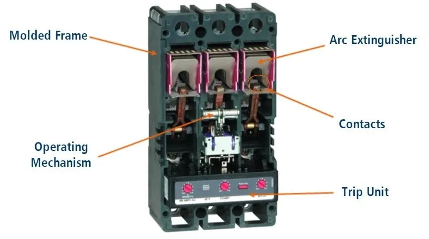
A Circuit Breaker is an electrical switch which protects the electrical circuit from the damage caused by short circuit or overload. Circuit breakers are switches and they can be reset when it opens to prevent damage to components and overheating.
Working:
When an excess amount of current passes through a circuit breaker, it automatically opens the circuit and it will not allow the flow of current. It prevents from damaging the components from overheating and short circuit. Whenever the circuit gets opened, it has to closed manually in order to pass the current through the circuit again. By closing the switch the current will flow through the circuit. The breakers will also reduces the wear and tear which increases the lifetime value. Circuit breakers works same as fuse.
3. To find the Fuse rating:
Purpose of a Fuse:
Fuse is an electrical safety device which operates as a protection of overcurrent in an electrical circuit. The metal wire in the fuse will be cut off or may melt when excess amount of current flows through it.
Given data : Load = 10A
It is calculated based on Power, voltage and the load in the circuit.
P = V*I
Fuse rating, I = P/V
Where, P = Power in Watts(W)
V = Voltage in Volts(V)
I = Current in Amps(A)
Since the total load is 10A, The fusing rating will be higher than maximum amps.
So, we can take the fuse rating 14 - 16A fuse for the electric circuit.
4. To find the Voltage and Capacity of Battery:
Given data : Power = 500W ; Battery voltage = 12V(Assume)
Formula: Ah * V = Wh
Ah = Wh/V
So, Q = E/V
Where, Q = Battery Capacity (Ah)
E = Energy (Wh)
V = Voltage
Energy = Power * Time
= 500 * 1 [Assume Time as 1hr]
E = 500Wh
Battery capacity Q = E/V
= 500/12
Q = 41.67 Ah
60Ah Battery is a standard battery which is recommended.
So, the recommended battery voltage and capacity is 12V 60Ah Battery.
5. Elements which are connected in Parallel to each other and why?
Light switch connected with Lights:
The Light switch is connected parallel to all the lights because each light will require different amount of power when it is distributed.
Horn Button connected with Horns:
The Horn Button is connected parallel to horns. In order to operate, each horn will require different amount of currents but the voltage will remain the same.
6. Elements which are connected in Series to each other and why?
Battery connected to the Starter:
The Battery and the Starter are connected in series to each other. It is because the starter requires direct and very high current from the battery in order to start.
Gas Tank Unit connected to Fuel Gauge:
The Gas Tank Unit is connected in series to the Fuel Gauge. It is to measure the amount of Gas or Fuel present in the tank.
The Practical Automotive Wiring circuit is studied and analyzed.