Project
A
Project Report
on
"Simulation of an All-Terrain Vehicle"
Submitted by
Mr. Uphade Nikhil Dilip
Under the Guidance of
Mr. Vyshakh Raju
Title of Project :- Carry out a system-level simulation of an all-terrain vehicle.
Abstract :- The project report represents the system-level simulation of an all-terrain vehicle.In this project we have studied the how vehicle speed changes for changing the throttle input and also we have studied how to incorporate the CVT ratio into model by using lookup table.
Objectives :- To study the performance of all terrain vehicle for different input parameter.
Introduction :-
What is an All-Terrain Vehicle ?
An all-terrain vehicle (ATV) is defined as a motorized off-highway vehicle designed to travel on four low-pressure or non-pneumatic tires. An all-terrain vehicle (ATV) also known as a light utility vehicle (LUV)
Components of a ATV :- The componenets of a ATV are Vehicle Body, Suspension, Tire, Engine and CVT.
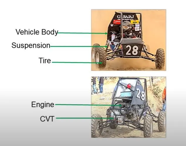
ATV Model in Simulink :-
The ATV model in simulink is shown in following fig. The main block in model are generic engine , CVT and vehicle body.The throttle and brake input given to generic engine with the help of signal builder. And CVT ratio also given to CVT block.
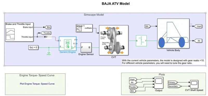
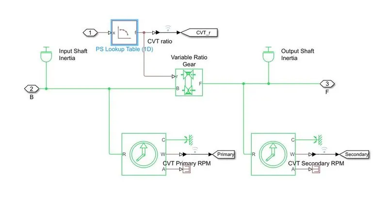
As shown in above image there is a CVT block which getting input signal from generic engine block and cvt ratio is provided by separate signal builder block.The CVT block is created in simpscape that shown in following image.
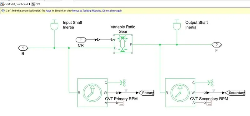
In CVT system there is primary and secondary shaft , inertia of shafts is provided to respective ports of variable ratio gear block .
Output of CVT system is provided to Vehicle Body block through speed reduction block.The vehicle body system which is created in simscape is shown in following image.
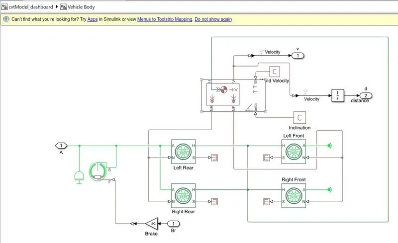
From above Vehicle Body system we getting vehicle velocity and distance.
Inputs Given to System :-
- Brake and Throttle Input - This value given to system with the help of signal builder. We kept brake input as 0 and throttle input varrying with time as per requirement.
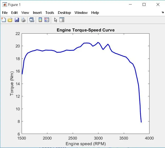
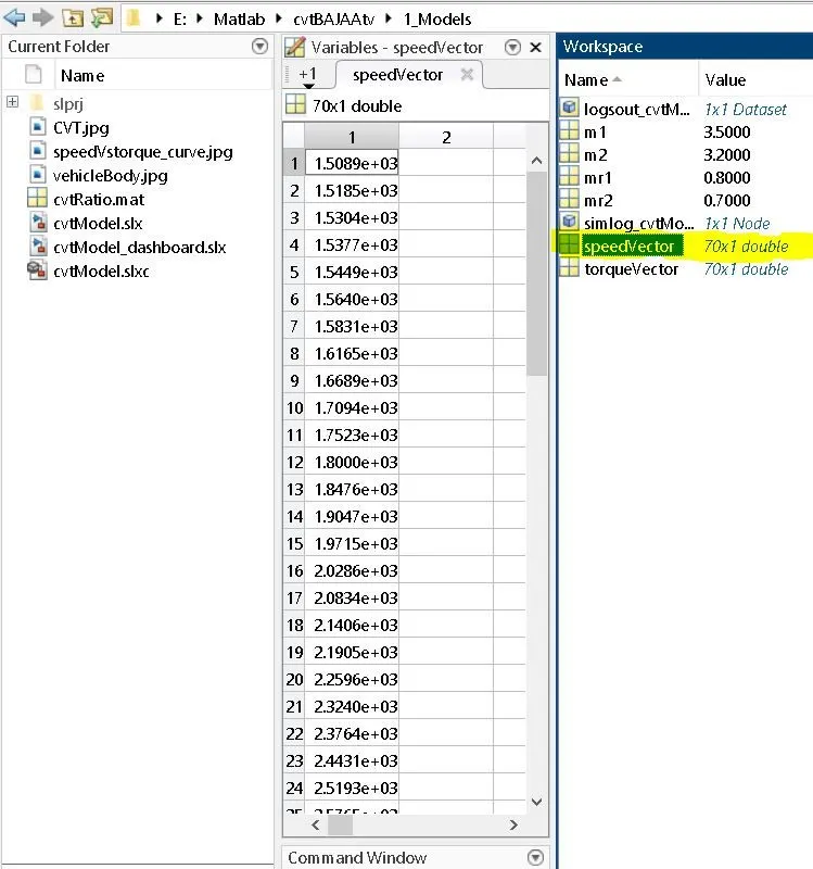
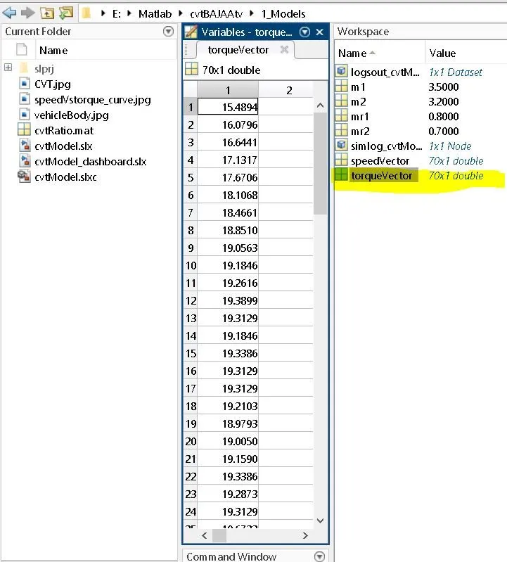
- Speed Vector and Torque Vector to Generic Engine - This values are imported from following image and then this values configured in workspace with variable name 'speedVector' and 'torqueVector' respectively.
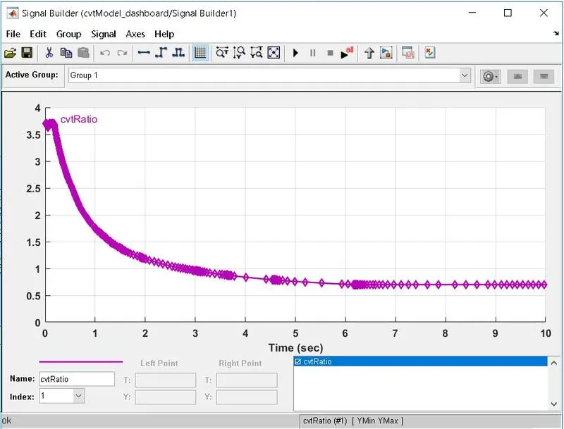
- CVT ratio - This values provided with the help of signal builder.
- Inertia of Input and Output Shaft - This value configured in workspace with variable name m1 and m2.(m1=3.5; m2=3.2)
- Teeth Ratio of Simple Gear - 10
- Mass of Vehicle Body - 250 kg
We have understood the overall ATV simulink model. For studying effect of various parameter on vehicle ouput we have to do some changes in input source.
STUDY-1
Effect of Throttle Input on Vehicle Velocity - For simulating effect of Throttle Input on Vehicle Velocity, we have to give different values of throttle input. For giving different values of throttle with time we have to replace signal builder block with knob.This replacement shown in following image.
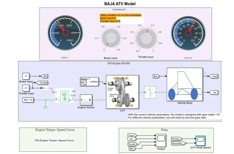
With this replacement it is easy to change the throttle value by knob.We kept brake input 0 and throttle input is varrying between 0.3 to 1.The effect of throttle input on vehicle velocity is shown in following image.
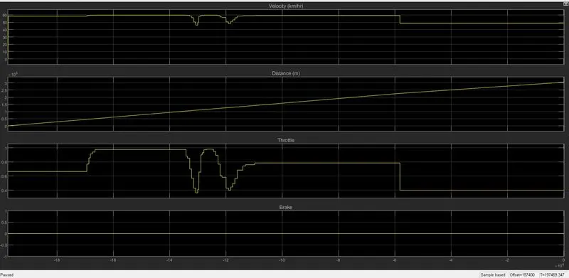
Result-From above image we observed that vehicle velocity increases with increasing throttle input and decreases with decrease in value of throttle input.
STUDY-2
Incorporating CVT data into model -
In above study we was giving random value of CVT ratio and checking vehicle performance but this is not realistic approach because CVT ratio is depending on vehicle velocity.That's why we have to build close loop model by using lookup table.
We have written a script to extract data of vehicle speed and cvt ratio from above open loop model and we get relation between Vehicle speed and cvt ratio and then we giving this data to lookup table.
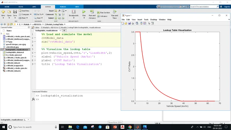
This data we used for lookup table in following model.
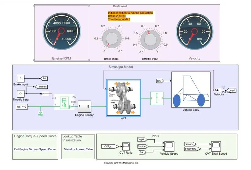 As we can see that in above model we remove that cvt ratio signal builder and there is feedback coming from vehicle velocity that given to cvt block.
Inside CVT block there is lookup table, based on the values given to lookup table we get required CVT ratio.
From above study we have get result of how primaray and secondary shaft RPM of cvt get changed.

Result :-
From above image we noticed that there is change in secondary shaft RPM based on the RPM of primary shaft.