Project 3
Aim of the Project-
Design and simulation of Buck converter for Auxiliary load in EV.
- Input voltage is 48V, Output voltage is 12 V
- Load current is 10A
- Calculate Duty ratio and Load(use Resistor as Load)
- Calculate L,C
Theory-
The buck, or step-down, converter is a widely used DC/DC switching regulator.
A step-down DC/DC converter is a device capable of converting an unregulated input voltage into an regulated output voltage lower than the input voltage (step-down, Vout < Vin).
The buck converter is composed of a switch (made with a MOSFET) driven by a wave square, a diode, and an LC filter. The value of the frequency of the PWM, with the value of L and C, determine the output voltage in the circuit.
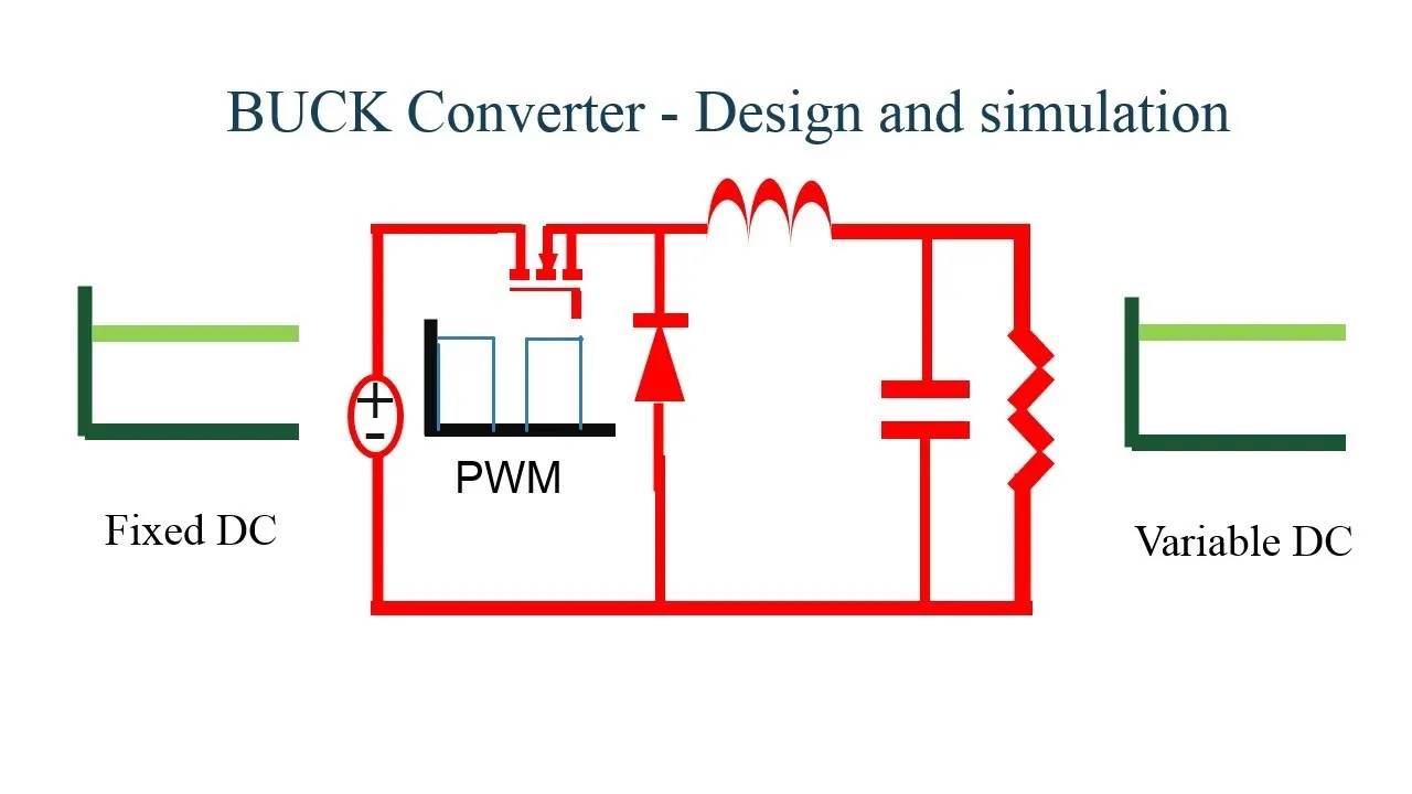
It is comprised of
1. Switching power supply unit which, can turn ON/OFF switching elements that can be turned ON/OFF at high frequency to convert a dc input voltage Vin into a dc output voltage Vout.
2. Control unit, which is used to control the ON/OFF operation of the switching element. We use MOSFET as switching element where the pulse generator is a control unit for MOSFET.
3. Inductor - It stores the energy during ON period & dissipates during OFF period.
4. Capacitor- It bypass the ripple content in the output voltage
5. Freewheeling diode- It freewheel the current through the resistor from the inductor & circuilate it in circuit during OFF period.
6. Load Resistor- Across it we can measure the output voltage & current through it.
Given data,
Input Voltage Vin = 48 V
Output Voltage Vout = 12 V
Load current iL = 10 A
Mathematical Formulae-
Output Voltage = Load resistor * Load current
Vout = R * iL
Load Resistor = Output Voltage / Load current
%Duty ratio D = (Vout / Vin) * 100
Minimum Inductance Lmin = [(1-D)*R] / (2*f)
Maximum Inductance L = 1.25 * Lmin
Capacitance C = (1-D) / (8*L*r*f^2)
Ripple factor r = Change in output voltage / rated output voltage
Assumptions:
1. The switching frequency(f) of the buck converter is taken to be 40 KHz.
2. Ripple factor (r) is assume to be 0.5%
Calculations-
Load resistor R = Vout / iL = 12/10 = 1.2 ohm.
Duty ratio(cycle) D = Vout / Vin = 12 / 48 = 0.25
% D = = 0.25*100 = 25%
Minimum Inductance Lmin = [(1-D)*R] / (2*f)
Lmin = [(1.025)*1.2] / (2*40000) = 11.25 micro henry
Maximum Inductance L = 1.25 * Lmin = 14 micro henry
L = 1.25 * Lmin = 14 micro henry.
Capacitance C = (1-D) / (8*L*r*f^2)
C = (1-0.25) / (8*14*10^-6*r*40000^2) = 837 micro farad.
Simulink model block description
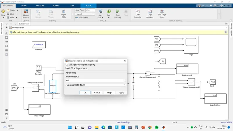
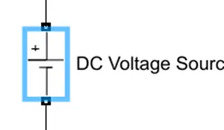
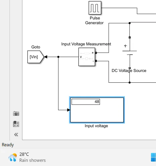
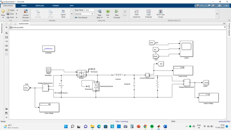
1. DC voltage source - we can use DC voltage source because we need DC voltage in output & Buck converter is DC-DC converter.
This block is used here for the Input providing 48V. The DC Voltage Source block represents a constant voltage source whose output voltage value is independent of the current through the source.
we set the value of DC voltage source to be 48 V. It can be measured by voltage measurement.
2. Switching device -
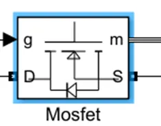
MOSFET and internal diode in parallel with a series RC snubber circuit. When a gate signal is applied the MOSFET conducts and acts as a resistance (Ron) in both directions. If the gate signal falls to zero when the current is negative, the current is transferred to the antiparallel diode.
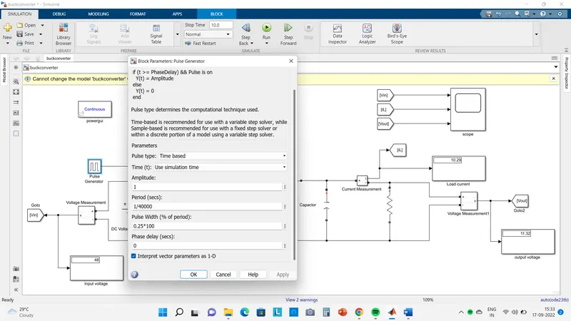
3. Control unit- We use the pulse generator as Control unit.
Control unit parameter input is given through duty cycle.
Duty ratio(D): It is nothing but the ratio of the input voltage source to Output voltage is known as duty ratio its formula is shown below and find out the value.
duty ratio (D) = Vo/Vs
= 12/48
= 1/4
=0.25
4. Diode:-
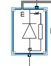
Implements a diode in parallel with a series RC snubber circuit. In on-state, the Diode model has an internal resistance (Ron) and inductance (Lon). For most applications, the internal inductance should be set to zero. The Diode impedance is infinite in off-state mode.
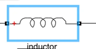
Inductor:- Use the 'Branch type' parameter to add or remove elements from the branch.
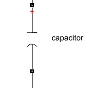
Capacitor:- a symbol of a capacitor this block is used for the storage of the electric energy for providing Output voltage when required.
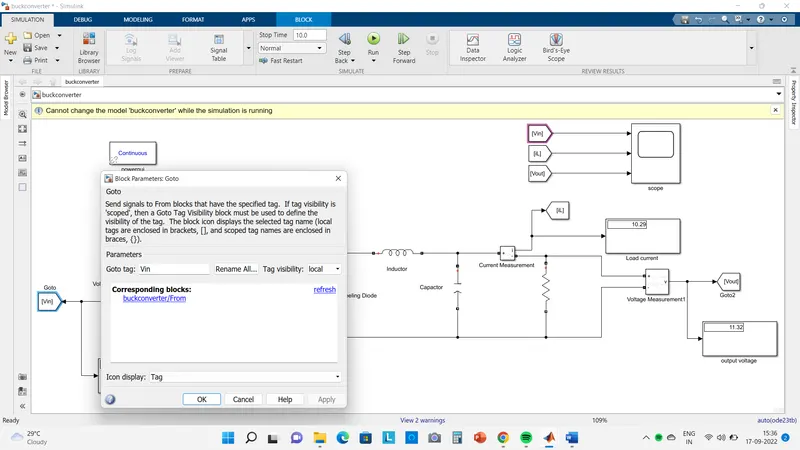
GOTO block:- Send signals to From blocks that have the specified tag. If tag visibility is 'scoped', then a Goto Tag Visibility block must be used to define the visibility of the tag. The block icon displays the selected tag name (local tags are enclosed in brackets, [], and scoped tag names are enclosed in braces, {})
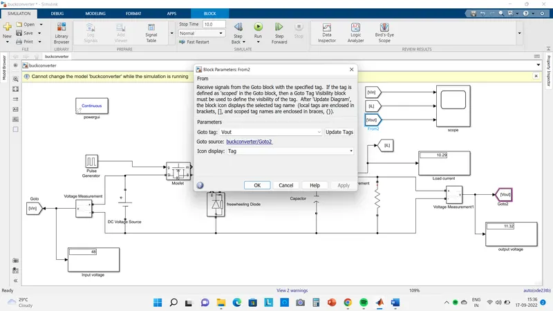
From block:- Receive signals from the Goto block with the specified tag. If the tag is defined as 'scoped' in the Goto block, then a Goto Tag Visibility block must be used to define the visibility of the tag.
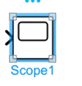
Scope block:- The Simulink Scope block and DSP System Toolbox Time Scope block display time domain signals.
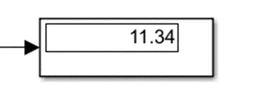
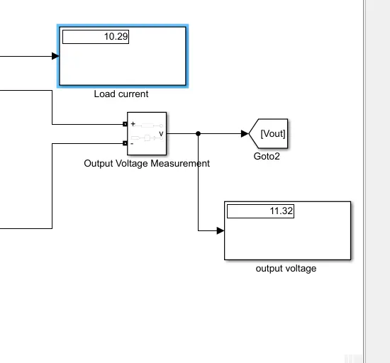
Display block:- This block uses the display of the Output value of Voltage, Current & input voltage
Whole Simulink Model-
Observation-
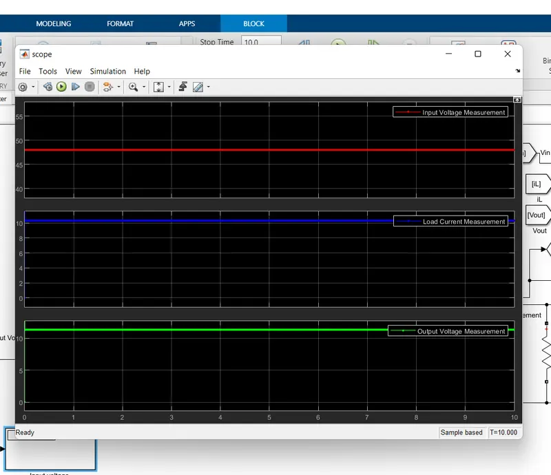
from the waveform & display block we get the required output voltage= 11.32V, Load current=10.29A In the observation little bit variation which may due to chemistry of battery & losses.
Conclusion-
In this project a method is illustrated for Buck converter design in simulation which is based on theorotical calculations first & then computed in simulink environment. When the assume data is vary person to person by referring different frequencies & ripple factor then variation may occure in calculation & feeding the data to simulink blocks. I refer the frequency to 40KHz & ripple factor to 0.5% & do the calculations & build the simulink model with given methods. We do the calculations correctly & the method/steps which i follow provides better accuracy Therefore this technique can be attractive & effective approach for building buck converter.