Project 2 Thermal modeling of battery pack
THERMAL MODELLING OF BATTERY PACK
Introduction
Electric Vehicle (EV) is type of vehicle which primarily powered by an electric motor drawing power from a rechargeable energy storage device. EV receives electricity by plugging into the grid and store it in batteries. There are many reasons why people are moving to Electric Vehicles (EV) to get them to the places they need to be. These include:
- EVs are fun to drive because they are fast and smooth.
- Many studies show that the emissions from burning fossil fuels such as gasoline produce harmful greenhouse gases. EV’s produce no smelly fumes or harmful greenhouse gases.
- EVs are innovative and cool.
- EVs are a smart and convenient choice.
These vehicles can be divided into three categories:
- Hybrid electric vehicles (HEVs)
- Plug-in hybrid electric vehicles (PHEVs)
- All-electric vehicles (EVs)
Together, PHEVs and EVs can also be referred to as plug-in electric vehicles (PEVs).
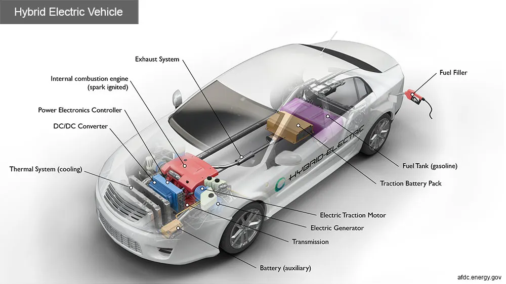
Hybrid Electric Vehicles (HEVs) have two complementary drive systems: a gasoline engine with a fuel tank; and an electric motor with a battery. Both the engine and the electric motor can turn the transmission at the same time, and the transmission then turns the wheels. HEVs cannot be recharged from the electricity grid – all their energy comes from gasoline and from regenerative braking.
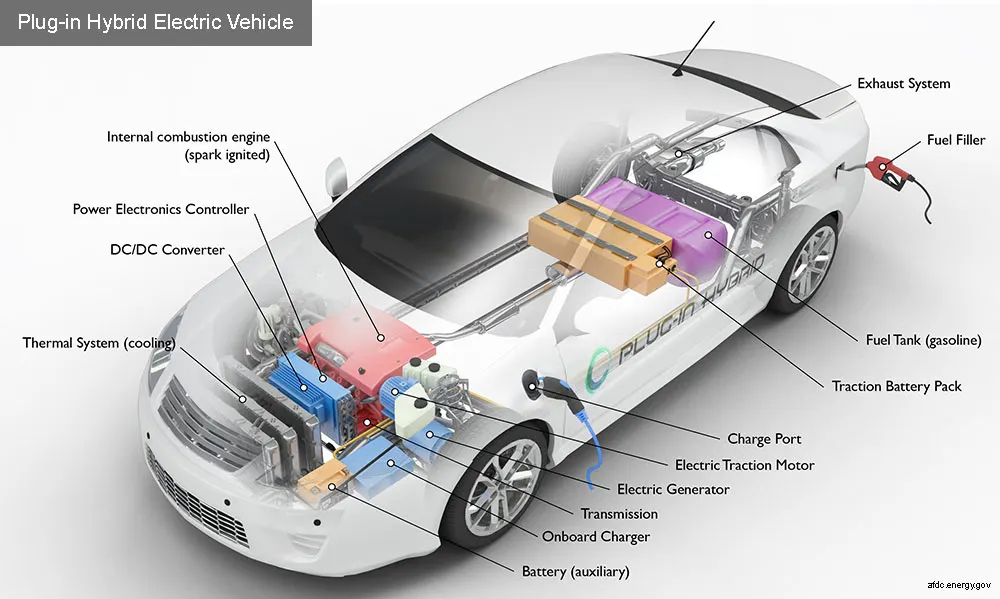
Plug-in hybrids (PHEVs) use an electric motor and battery that can be plugged into the power grid to charge the battery, but also has the support of an internal combustion engine that may be used to recharge the vehicle’s battery and/or to replace the electric motor when the battery is low. Because Plug-in Hybrids use electricity from the power grid, they often realize more savings in fuel costs than tradition hybrids electric vehicles (HEV).
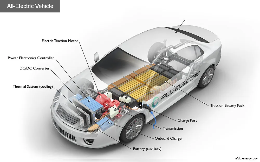
A battery electric vehicle (BEV) runs entirely using an electric motor and battery, without the support of a traditional internal combustion engine, and must be plugged into an external source of electricity to recharge its battery. Like all electric vehicles, BEVs can also recharge their batteries through a process known as regenerative braking, which uses the vehicle’s electric motor to assist in slowing the vehicle, and to recover some of the energy normally converted to heat by the brakes.
Charging of Battery
The heart of the Electric Vehicle are the batteries also known as Traction batteries which are used to power the EVs. These are rechargeable batteries or secondary batteries which are typically Lithium Ion Batteries. These batteries are specifically designed for a high Ampere Hour (or kilowatt-hour) capacity. EV receives electricity by plugging into the grid and store it in batteries. They also receive energy during regenerative braking and also when the vehicle is going uphill or downhill. This time the motor will working in generative mode, providing energy to battery.
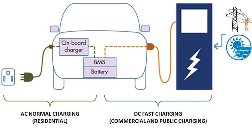
EV Charger is an electrical device that converts alternating current energy to regulated direct current for restocking the energy of an energy storage device (i.e. battery) and may also provide energy for operating auxiliary electrical systems.
There are 3 functions that must be performed to allow charging of the EV battery from an electric supply network. The two of them is electrical functions and other one is mechanical function. First electrical function is rectification process and second one is controlling and regulation of supply voltage according to battery charge acceptance characteristics. The mechanical function is the connecting of the EV to the Electric Vehicle Supply Equipment (EVSE) and this process is performed by the user.
The charging scheme is a combination of the charging and termination methods. The charger has three key functions:
- Getting the charge into the battery (Charging)
- Optimising the charging rate (Stabilising)
iii. Knowing when to stop (Terminating)
Electric vehicle battery chargers divided into two types: on-board type (in electric vehicle) and off-board type (at a fixed location).
Thermal Management System
In both HEVs and PEVs, the battery pack is a key component of their fuel savings potential. The battery is also one of the most expensive components in the vehicle. The battery’s performance unavoidably declines over the life of the vehicle, therefore battery must be carefully managed to minimize degradation which affects vehicle performance and fuel consumption.
Temperature is one of the significant factors affecting battery performance and life. If the battery is operated at high temperatures, it can lead to damaging electrochemical side reactions. For some batteries, higher temperatures will also increase the internal rates of thermal reactions, which lead to even greater heat generation, higher temperatures, and a “thermal runaway” condition potentially ending in fire or explosion.
To avoid the adverse impacts of high-temperature conditions a Thermal Management System is required to monitor the temperature and to provide effective cooling. Battery systems designed for vehicle applications typically employ convective thermal management in the form of air or liquid cooling. Thermal management system designs can vary widely in complexity and in cost.
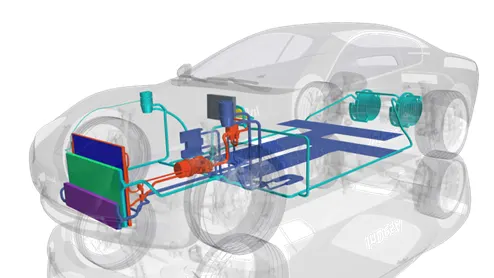
A battery pack consists of many batteries which are connected in series and parallel combinations to achieve high Voltage and High Ampere Hour Capacity. The temperature of the battery pack must be well monitored. Otherwise degradation of Cell occurs.
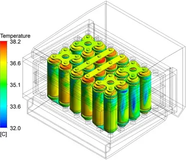
Heat generated of the battery pack during charging process is shown in figure. It is seen that the temperature of the middle cells are high compared to those that are on the sides. That means the heat generated in the middle of the battery pack cannot dissipate easily. One such battery pack is modelled here for case study analysis.
In this project a battery pack consists of 10 Lithium ion cells are modelled which are connected in series. It is modelled in such a way when it is simulated under various conditions, the temperature of the cells which are connected in the center of the battery pack are high and its performance are low when compared to the other cells in the battery pack. This will be explained under two case studies
- Thermal Modelling of Battery Pack during Discharging at various ambient temperature
- Thermal modelling of Battery Pack during Charging at various ambient temperature
- Fast Charging Mode: CC charging
- Constant Current Constant Voltage Charging
Thermal Modelling of Battery Pack during Discharging at various ambient temperature
Model Description
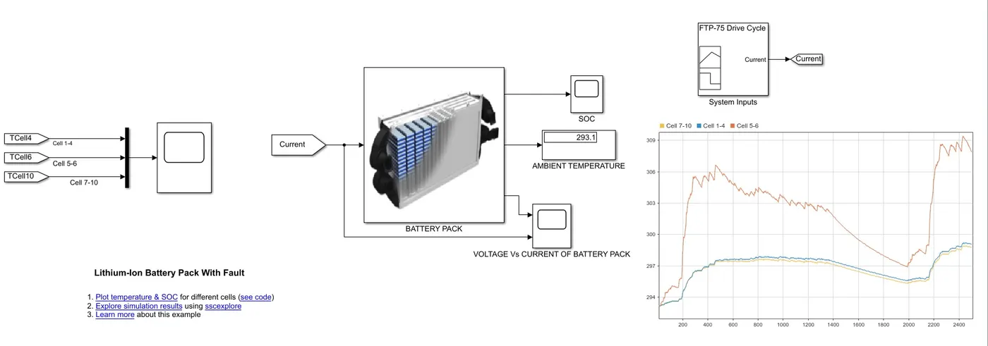
For explaining the thermal effects, the Lithium ion Battery Pack with fault reference model was taken. This model simulate a battery pack consists of 10 cells connected in series. In this model it is shown that the cells which are in the middle of the battery pack is heated up more than the adjacent cells which are on the side.
The cells 5 and 6 are modelled as inner cells where the heat dissipation of these cells are through conduction and for the remaining cells, the heat dissipation is through convection to the atmosphere.
Battery Pack
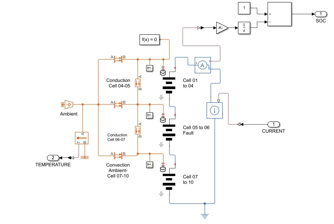
The configuration of the cells in the 3 modules are as shown below. The first module consists of cells from 1 to 4 the second module consists of cells 5 and 6. The third module consists of cells from 7 to 10.
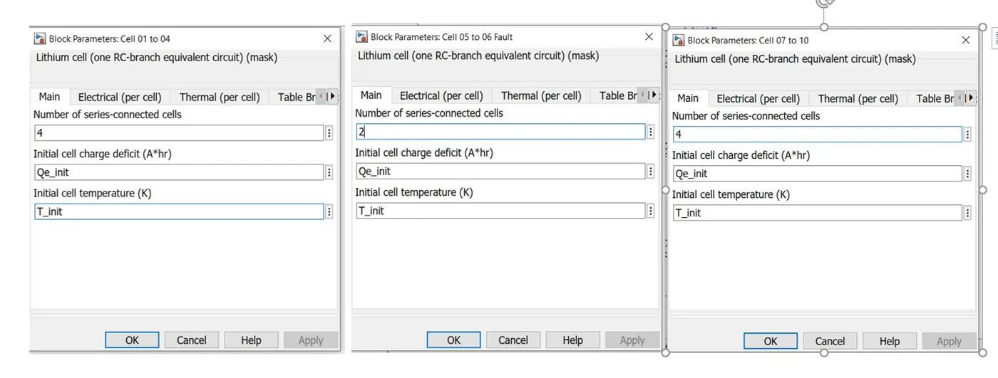
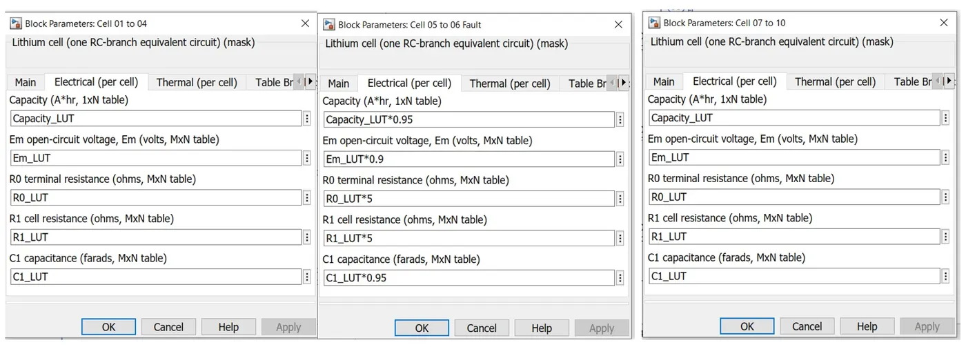
For simulating the thermal effects of module 2, a fault is introduced into the model. the electrical parameters of the module 2 has been changed so that the temperature of the module 3 is greater than the other modules. Thus justified.
Drive cycle
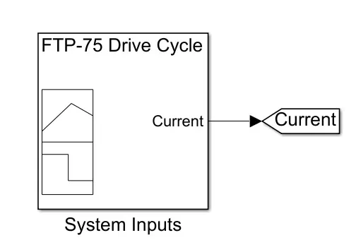
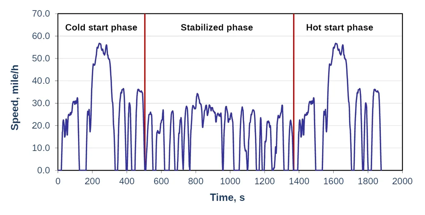
The EPA Federal Test Procedure, commonly known as FTP-75 for the city driving cycle are a series of tests defined by the US Environmental Protection Agency (EPA) to measure tail pipe emissions and fuel economy of passenger cars. It consists of the following segments.
- Cold start transient phase (ambient temperature 20-30°C), 0-505 s,
- Stabilized phase, 506-1372 s,
- Hot soak (min 540 s, max 660 s),
- Hot start transient phase, 0-505 s.
The following are some basic parameters of the cycle:
- Duration: 1877 s
- Distance travelled: 11.04 miles (17.77 km)
- Average speed: 21.2 mph (34.12 km/h).
- Maximum speed: 56.7 mph (91.25 km/h)
Case 1: Ambient Temperature is 25 degree Celsius = 298.15 Kelvin
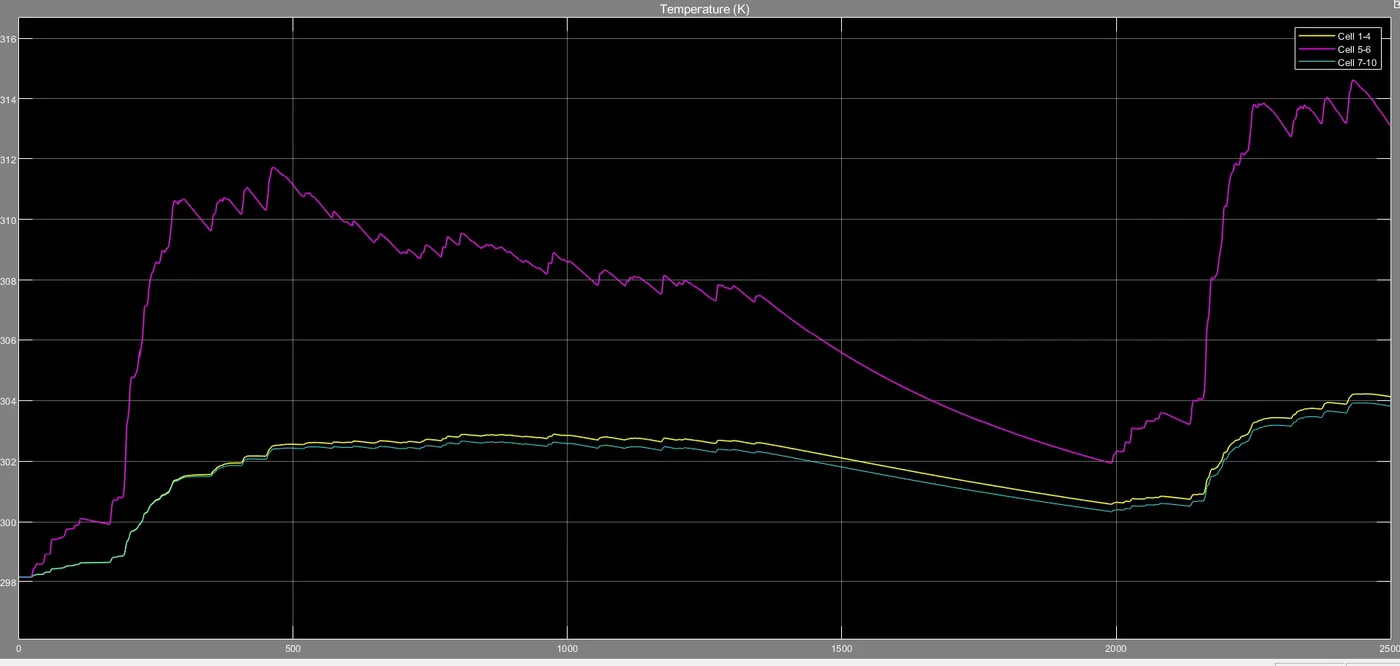
The initial temperature of the cells is 298K which is the ambient temperature. During the drive cycle, We can see that the temperature of 5th and 6th cells are more than the remaining cells as the heat dissipation in those cells are not efficient as compared to the remaining cells.
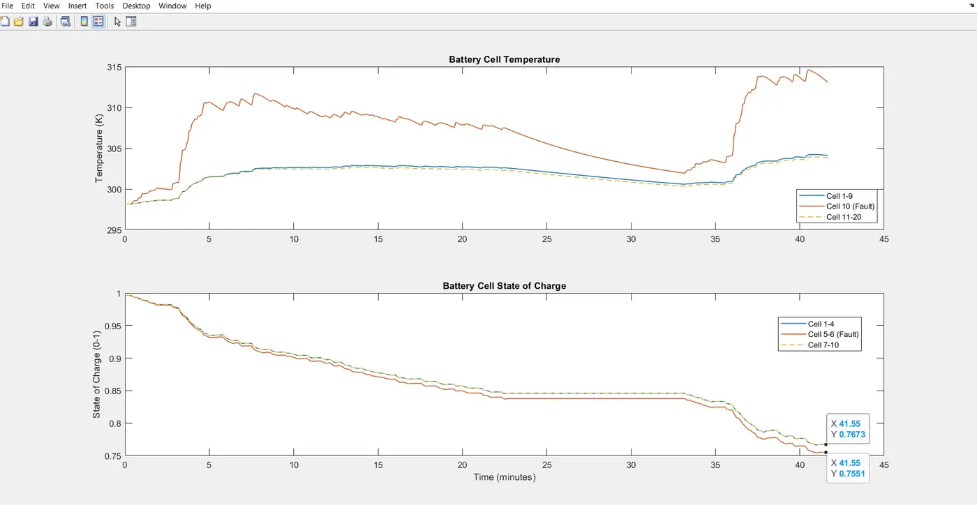
The initial SOC is 100%. SOC of the second module is decreasing faster due to increased temperature. At the end of the drive cycle, it is noted that the SOC of modules 1 and 3 is 76.73% whereas in the middle module, the SOC is 75.51%.
Case 2: Extreme Cold Conditions
Ambient Temperature: -10 degree Celsius = 263.15K
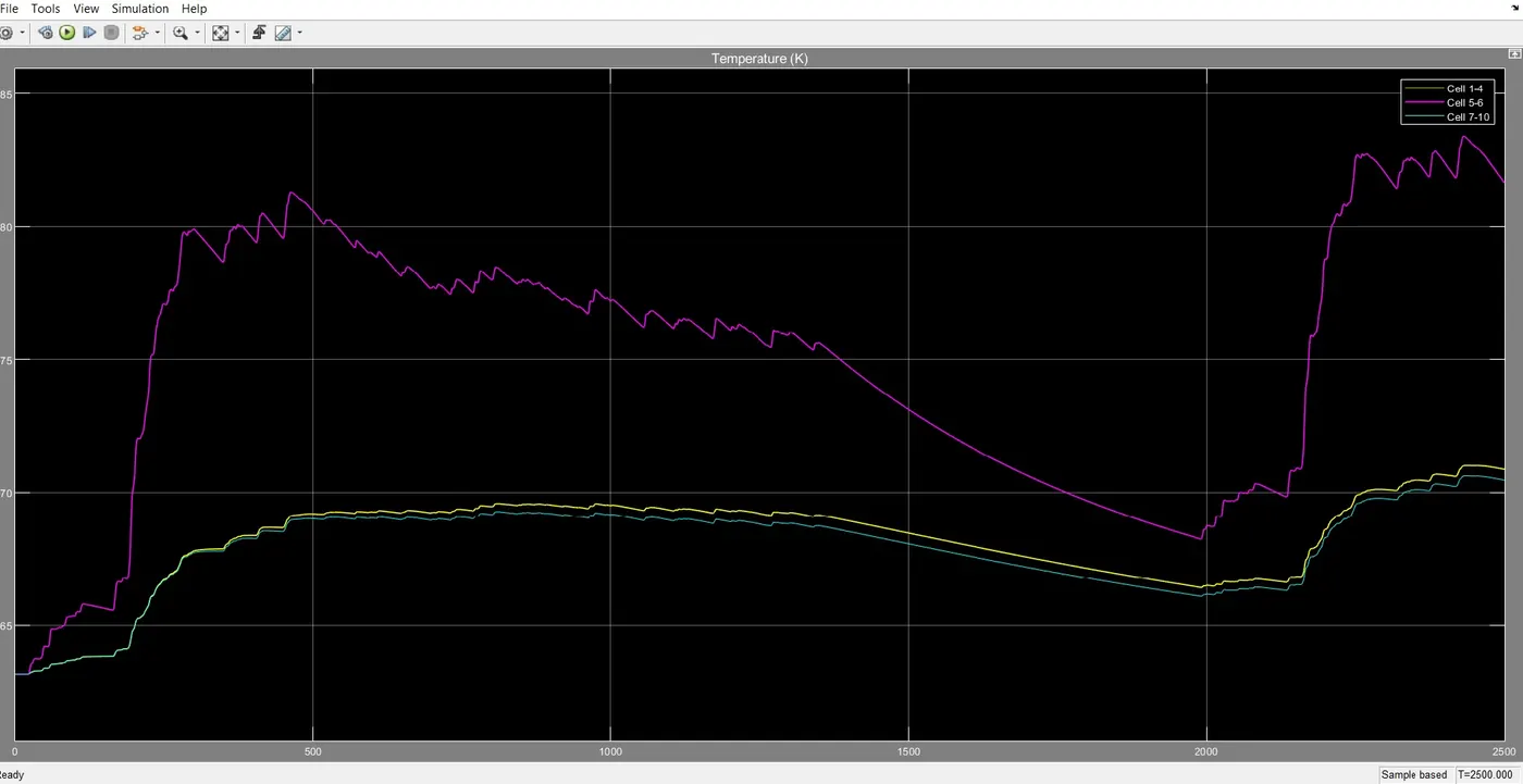
Here also the same observations can be noted. The cells 5 and 6 cannot dissipate heat efficiently.
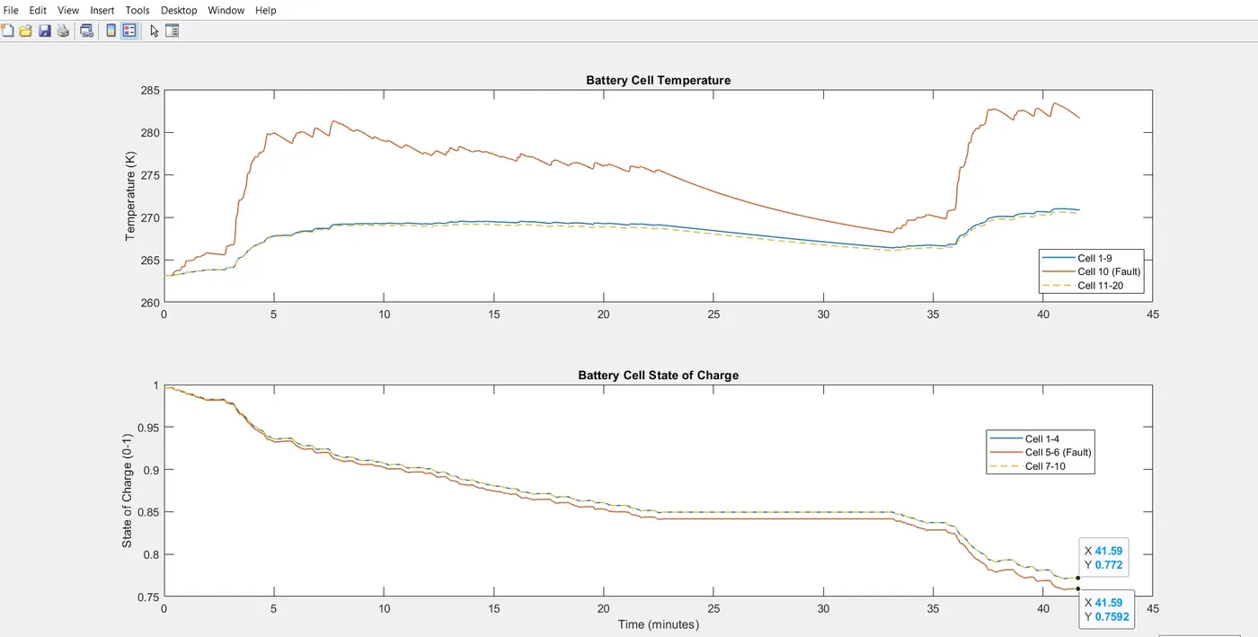
At the end of the drive cycle, it is noted that the SOC of modules 1 and 3 is 77.2% whereas in the middle module, the SOC is 75.9%.
Case 3: Extreme Hot Condition
Ambient temperature is 50 degree Celsius = 323.15K
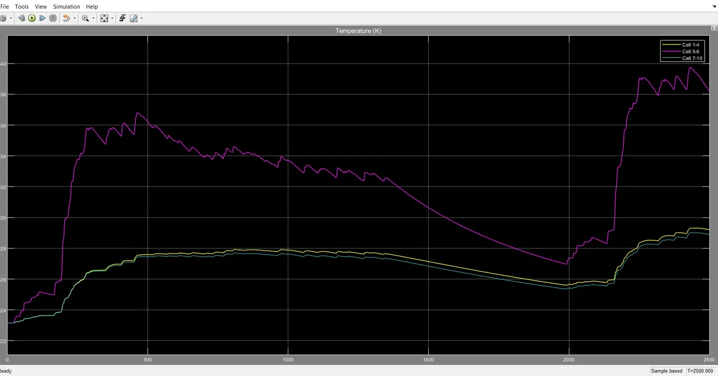
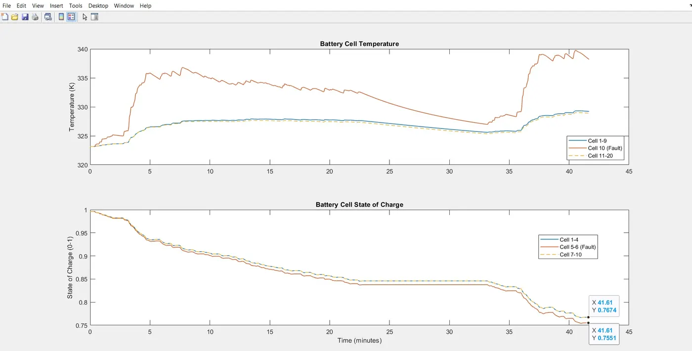
At the end of the drive cycle, it is noted that the SOC of modules 1 and 3 is 76.74% whereas in the middle module, the SOC is 75.51%.
Thermal Effects during DC Fast Charging
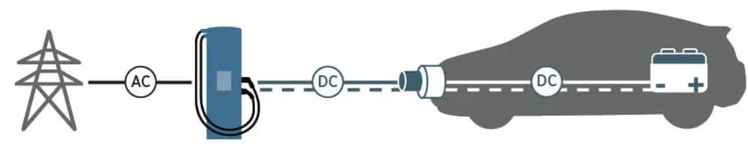
The charger is offboard the vehicle and supplies DC battery directly to the battery.
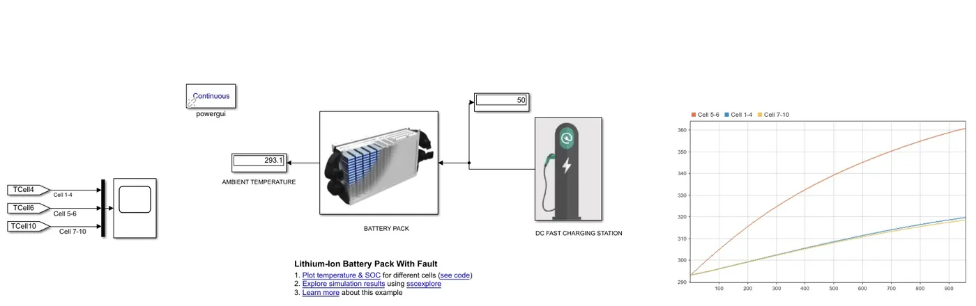
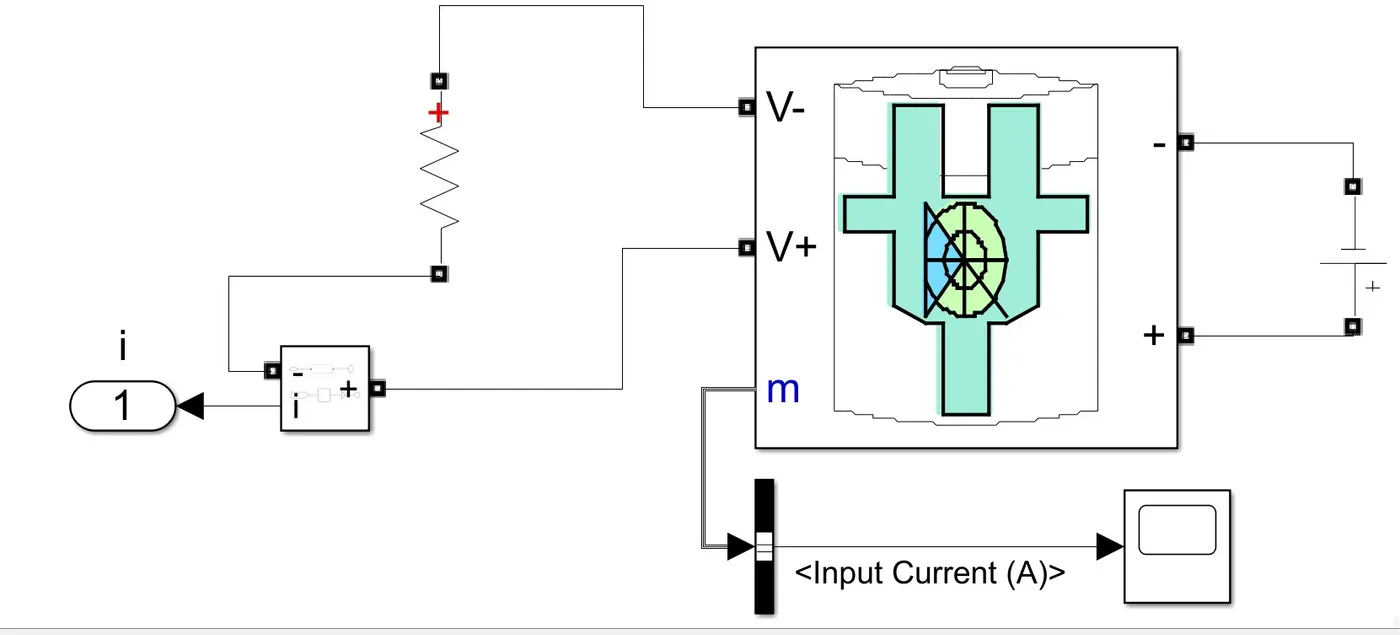
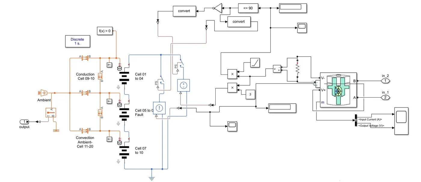
This is the model which simulates the DC fast charging.
Reference Specification of Battery Pack is Tata Nexon EV
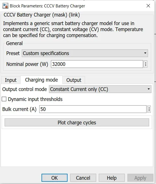
Fast Charging: Charging Time is 60 mins; Battery Capacity id 32kWh; therefore Dc Fast Charging Voltage is taken as 600VDC. And the current is found out to be 50A
Off board charger is modelled from the CCCV Battery Charger and made the following changes in the parameter.
Case 1: Ambient Temperature is 25 degree Celsius = 298.15 Kelvin

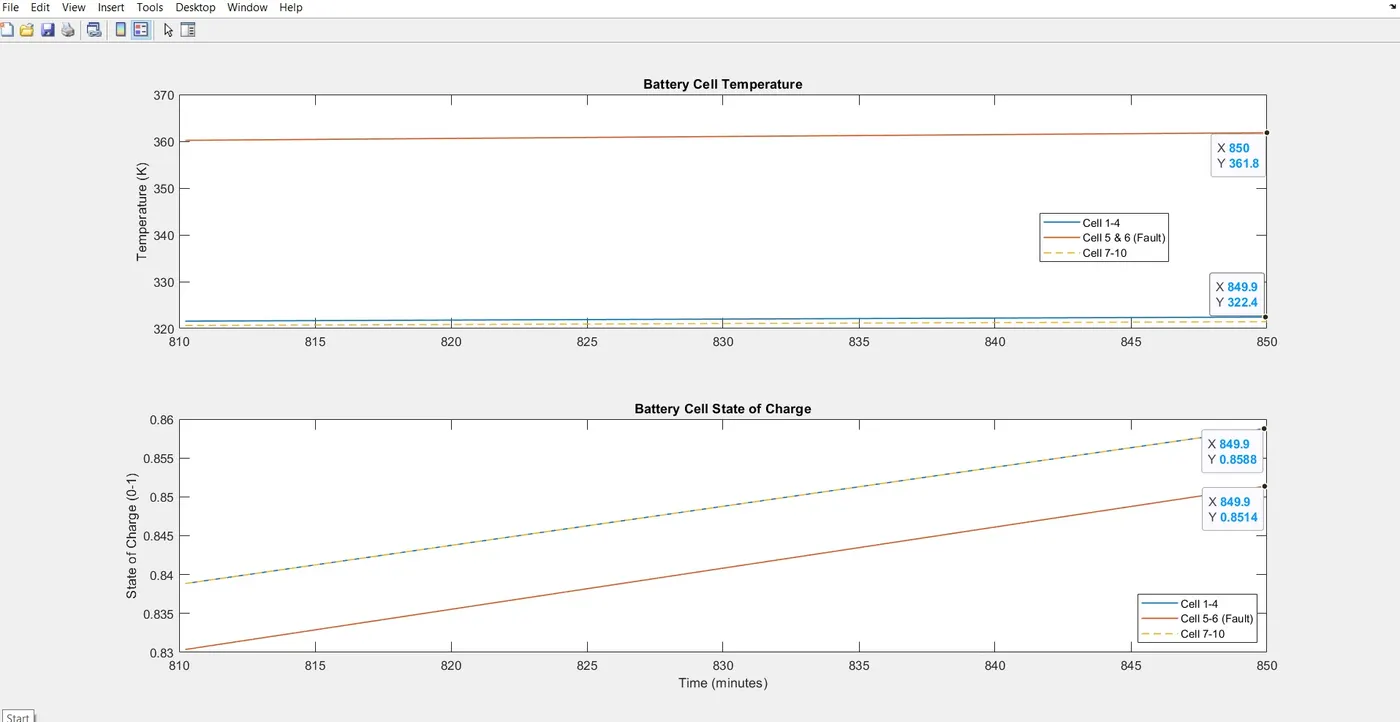
It is clearly shown that within 15 mins the SOC of the cells have reached 85.88% from initial SOC of 40% whereas the middle module cells SOC is lower. Due to increased temperature which is caused by the inefficient heat dissipate, those cells are charged slower which becomes the weak cell. It reduces the overall efficiency of the battery pack.
Case 2: Extreme Cold Conditions
Ambient Temperature: -10 degree Celsius = 263.15K

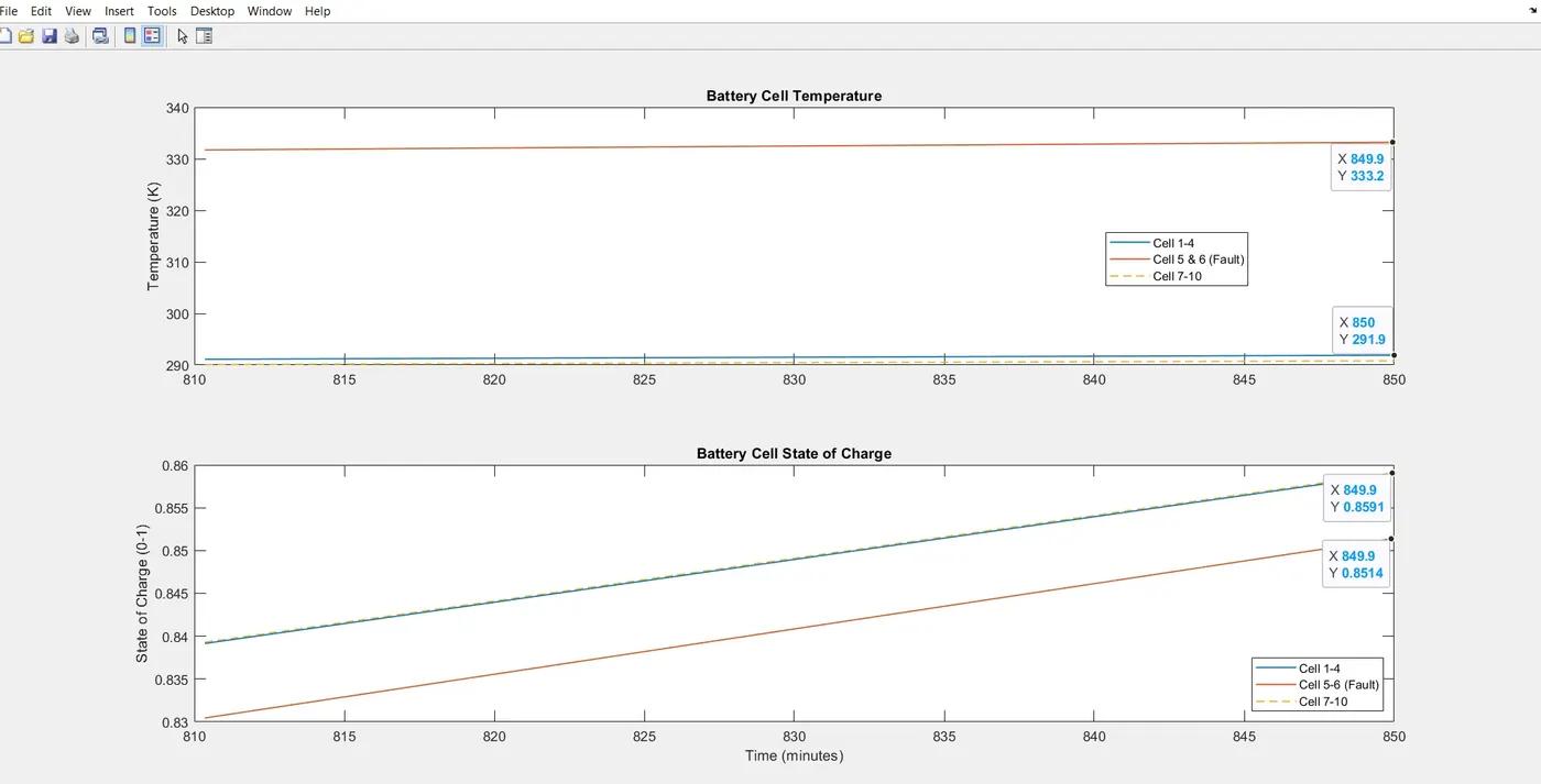
During cold conditions around -10 degree Celsius, the SOC is increased to 86% at the end of simulayion. Here also we can observe the same changes as before.
Case 3: Extreme Hot Condition
Ambient temperature is 50 degree Celsius = 323.15K

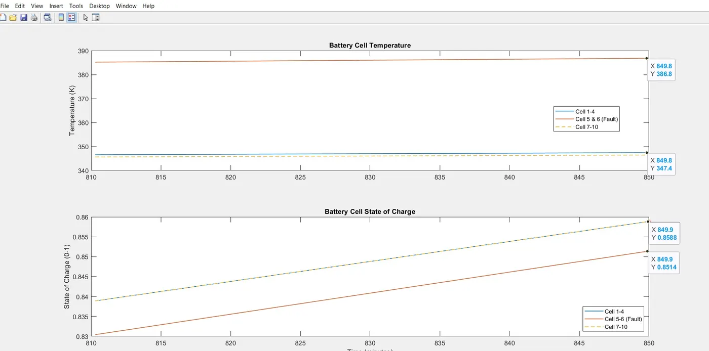
Thus it is understood the importance of cooling system in battery pack to improve the overall efficiency of the battery pack. If the temperature of all the cells are maintained properly, maximum capacity can be taken out from the cells. Thus the range and performance of EV can be improved.
Thermal Effects during CCCV Charging

AC power is supplied from the charging station to the onboard charger, which supplies DC power to the battery. The AC level which is taken from grid is 240V, 50Hz AC Supply.
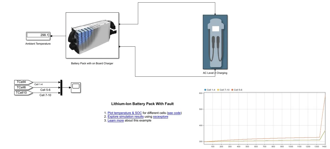
Battery Pack With Onboard Charger
The parameters of the CCCV Battery Charger are configured as follows:
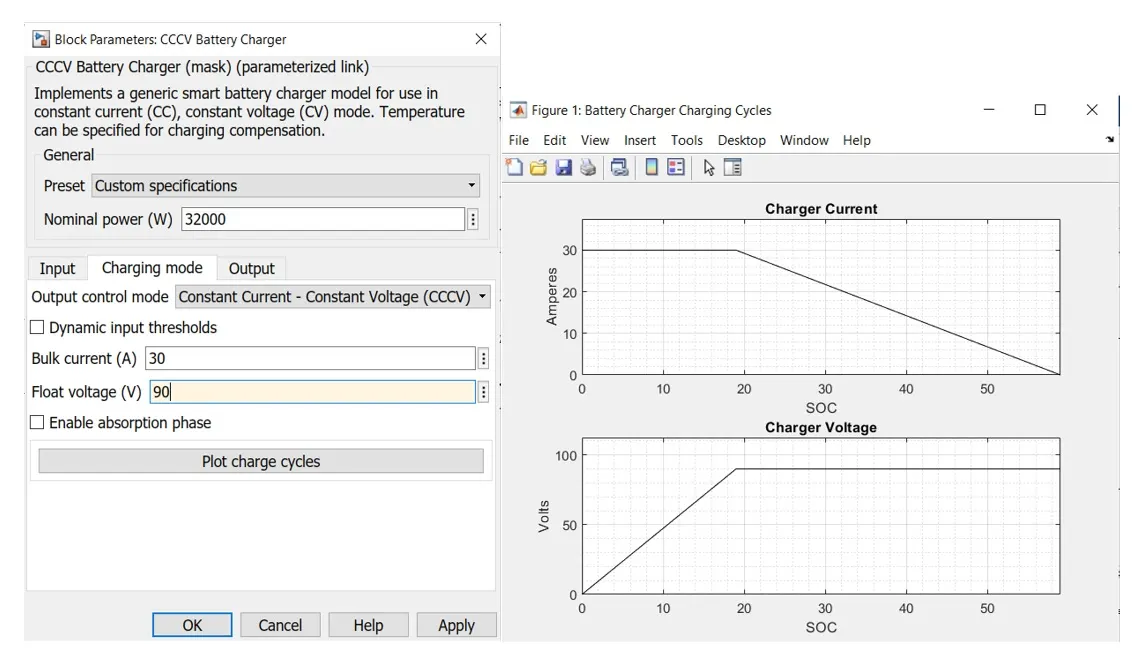
The CCCV mode of charging is implemented here. Until the Charging voltage becomes 90Vdc, battery will be charging in the constant current mode and later it is charged in the constant voltage mode. It is simulated under different scenarios.
Case 1: Ambient Temperature is 25 degree Celsius = 298.15 Kelvin
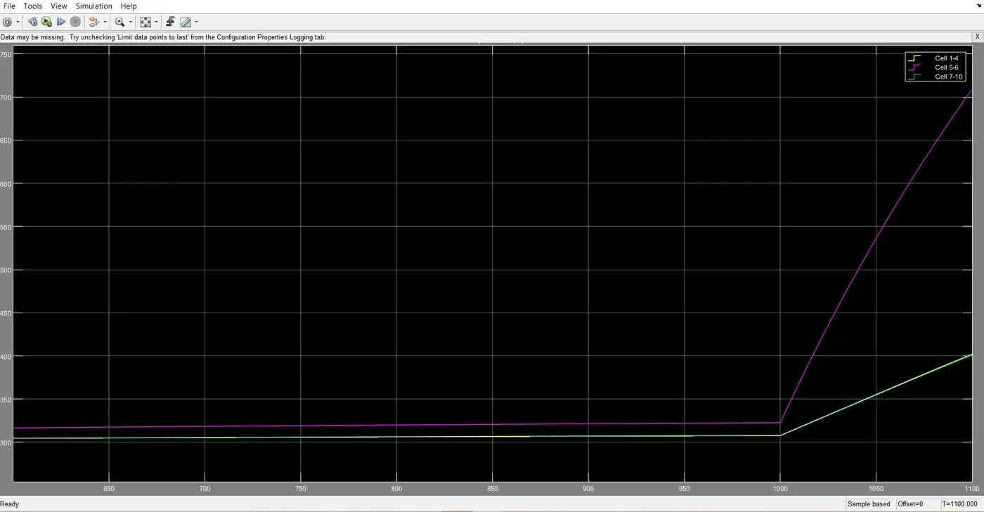
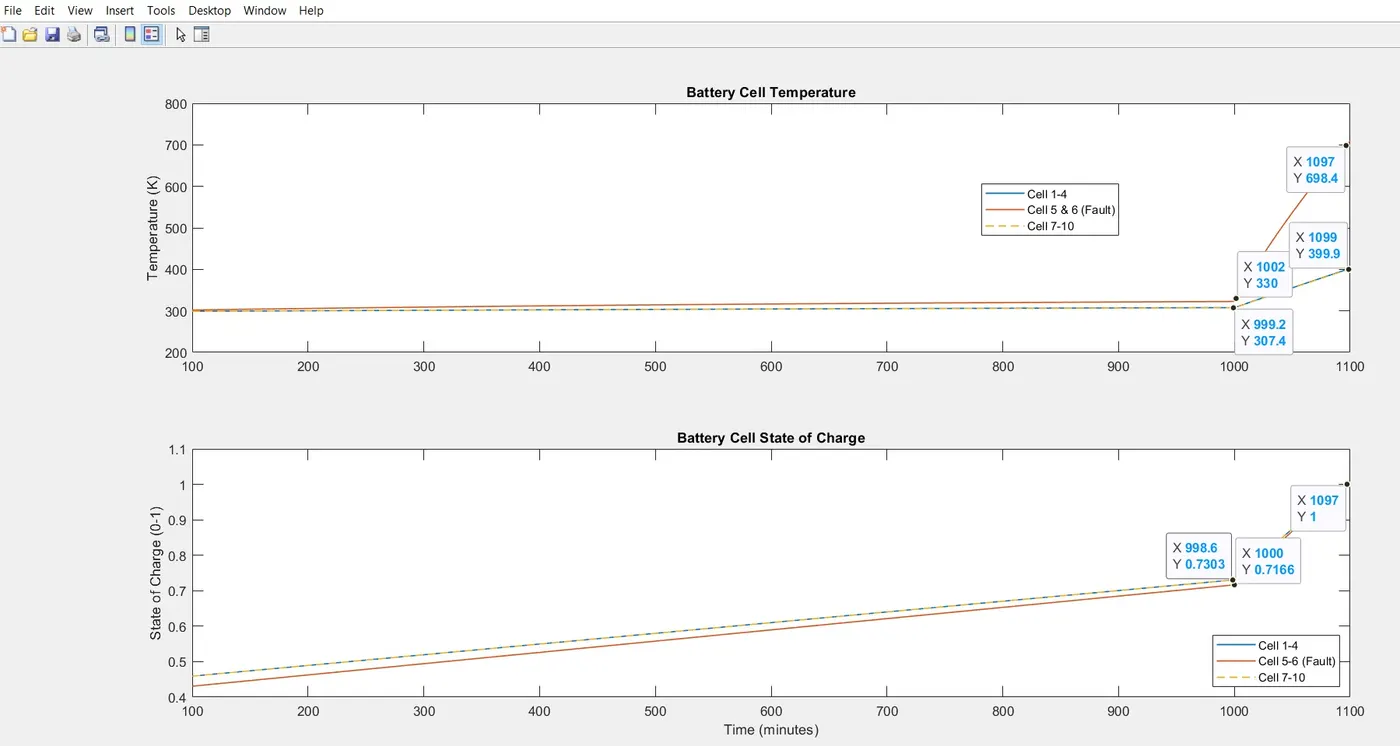
The module in the middle needs cooling techniques for efficient heat dissipation.
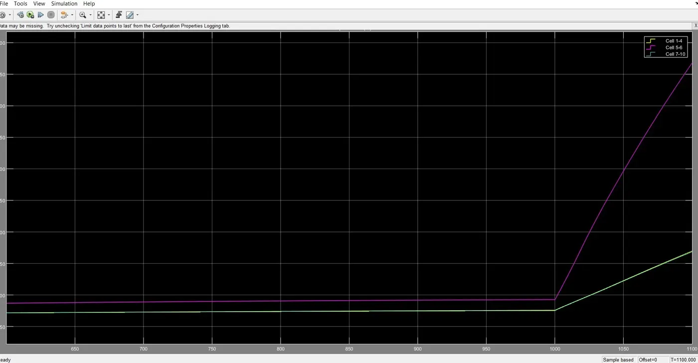
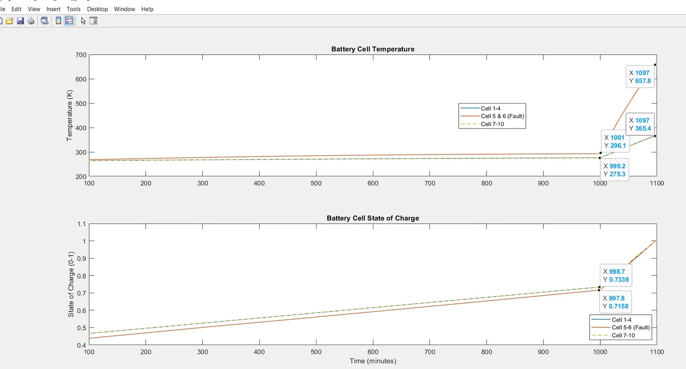
Case 2: Extreme Cold Conditions
Ambient Temperature: -10 degree Celsius = 263.15K
Case 3: Extreme Hot Condition
Ambient temperature is 50 degree Celsius = 323.15K
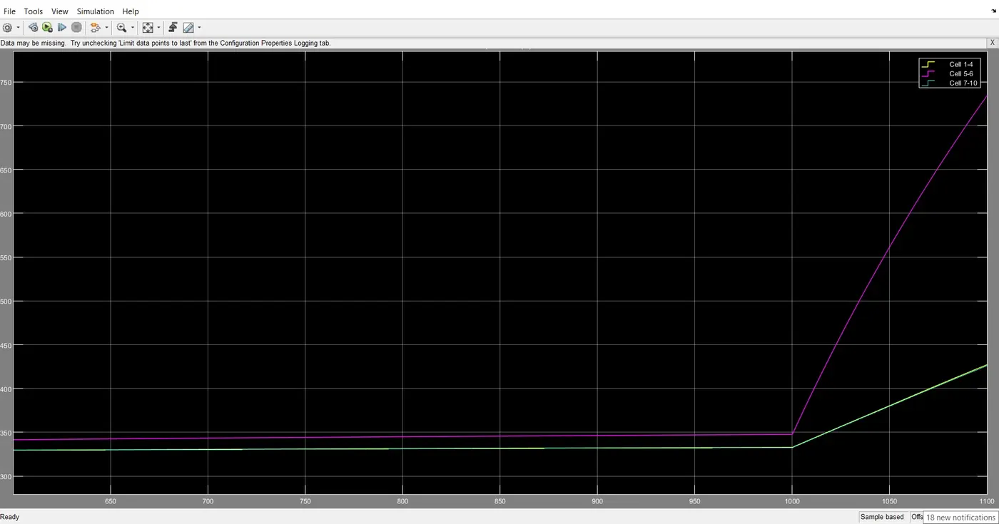
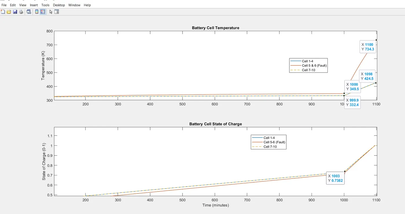
From these simulations, it is clear that the middle module requires efficient cooling techniques to main the temperature within limits. Otherwise, thermal runaway occurs which results in damage of the entire battery pack. Also, middle module being the weak cells, the overall performance of the battery is affected. Full capacity of the battery cannot be taken out. To avoid the adverse impacts of high-temperature conditions a Thermal Management System is required to monitor the temperature and to provide effective cooling. Hence, it is understood from these simulations, the effect of temperature on driving as well as charging for various climatic conditions.