Project 2 Thermal modeling of battery pack
Thermal Modeling of a Battery Pack
Aim:
* To model the thermal effects of a lithium ion Battery pack that will be used in a Real Time application such as an Electric vehicle or Hybrid Electric vehicle by making it to work on a Drive cycle load and study the effect of Temperature Rise in the performance of the battery pack.
* To Model a 10 cell configuration of a lithium ion cell connected in series in a battery pack and to simulate its Thermal effects
* To study on the Influence of the Thermal effects, in the battery pack's performance and estimate the State of Charge under various working conditions, like charging, discharging, etc.
Effect of High Temperature in Battery Pack:
* High temperatures promote growth of the solid electrolyte interface layer and increase the internal resistance, which would cause significant reduction in the power delivery.
* Under extreme conditions, the separator will melt, causing an internal short circuit which can potentially lead to thermal runaway of the cell.
* While higher temperatures can be tolerated temporarily, if the temperature is greater than 60 Degree C for a prolonged period with the battery fully charged, there is a risk that the batteries may rupture, explode or catch fire due to thermal runaway.
* Battery temperature and uniformity have a strong influence on the availability of the charging and discharging power, cell balancing and charge acceptance during regenerative braking.
* A large variation of temperature in a battery pack can lead to different cells charging and discharging at different rates and lead to electrically unbalanced cells and reduce the performance of the battery pack.
* Furthermore, the self-discharge rate will also be affected over a long period of time and can lead to a reduction in the effective operational state of charge.
Importance of Thermal Modeling of a Battery pack:
* It is very important to study on the effect of temperature in the a battery pack before using it on an application like Electric vehicle and Hybrid electrc vehicle.
* The lithium ion battery packs are widely used in electric vehicle application for many reasons and the battery pack are connected in series and in parallel as per the power requirements of the vehicle.
* When cells of the battery pack are connected in series or parallel connections based on the working conditions they Generate Heat and the cells at the middle of the battery pack will experience more temperature compared to the cells at the end.
* When a lithium cell becomes Hot beyond certain levels it will eat up the performance of the battery pack in areas like, Capacity, Life and safety.
* The Lithium ion cells when becoming very hot leads to safety issues like Thermal Runaway and even in some typical case it also has the risk of Explosion and this is certainly a thing that should never happen in an Electric vehicle.
* So, it is very important to do the Thermal modelling of a battery pack before actually installing it on any electric vehicle application.
* The Thermal modeling simulation will certainly prevent the adverse effects of the battery pack in an application, we can simulate the Effect of temperature in a battery pack and we can design the battery pack accordingly to scale up the performance of the battery pack.
Inbuild Thermal Modeling of a battery pack:
* For studying the temperature effects we are using the Inbuild simulink model, "Lithium Battery pack with Fault" model.
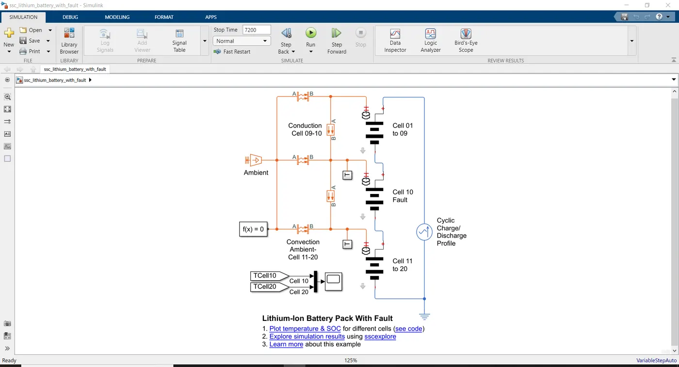
* This model shows how to simulate a battery pack consisting of multiple series-connected cells in an efficient manner.
* It also shows how a fault can be introduced into one of the cells to see the impact on battery performance and cell temperatures.
* For simulating the battery's performance and Temperature behaviour there is a load given so that we can simulate as if the battery is made to work under a particular usage condition.
* In this Model the load given is a cyclic Alternating current source which has a pak amplitude of 50 A and the Frequency (Charge and Discharge load in sinusoidal wave) is 1/600 Hertz.
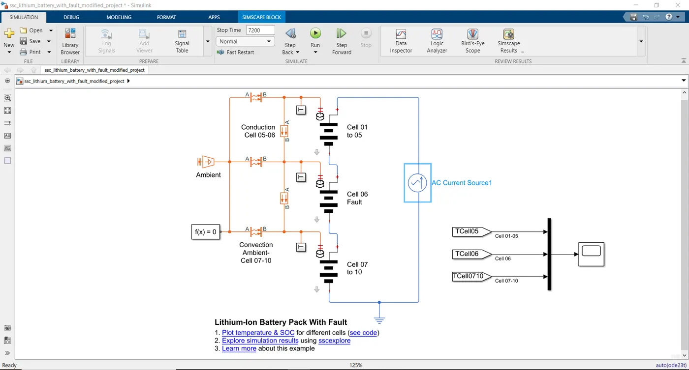
* This model is a inbuild simulink model which has Three Lithium battery packs connected in Series connection. The first battery pack has nine cells (from 1 to 9) in Total and the Third pack has Ten Cells in total (From 11 to 20), whereas the second battery pack has only one cell (10th Cell).
* The First and Third battery packs have the following cell parameters as default,
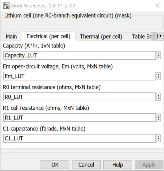
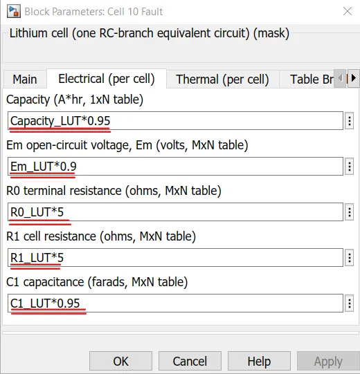
* The fault is represented by changing the parameters for the Cell 10 Fault subsystem, reducing both capacity and open-circuit voltage, and increasing the resistance values.
* By having diffent parameters With high internal resistance for the second battery pack which has only one cell, we can predict its undesirable temperature effects.
* The second battery's default parameters which has only one cell in Total,

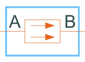
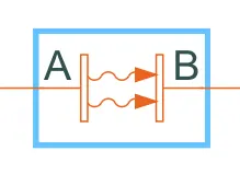
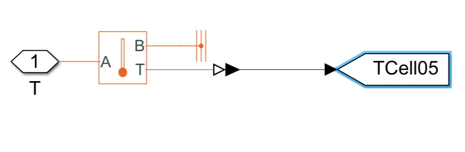
* The Temperature subsystem has a Temperature sensor and a reference block which senses the Temperature and sends the Values to the Goto block, the Goto block Send signals to From blocks that have the specified tag.
* Then these are Connected to a MUX Block ( Multiplex scalar or vector signals ). Then they are connected to the scope to visualize the Temperature Behaviour of the Battery pack based on the Load given to them to perform.
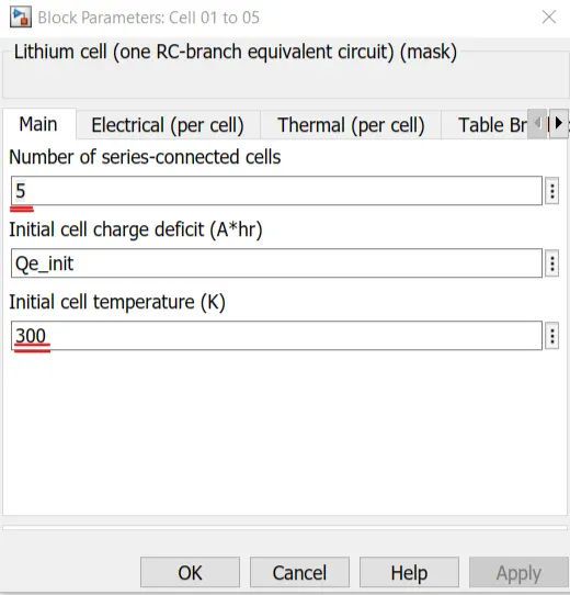
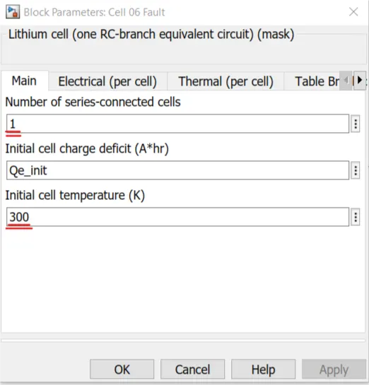
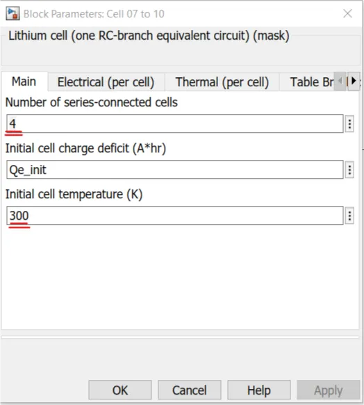
* These above Conditions can be simulated By slight Modifications to the Inbuild "Lithium Ion battery fault" Model available in Simulink.
1. Using a Drive Cycle Load Reference :
* The Model is First modified to have the battery supplying Power for a vehicle driving in FTP - Drive cycle and the
Thermal Behaviour is monitored and analysed.
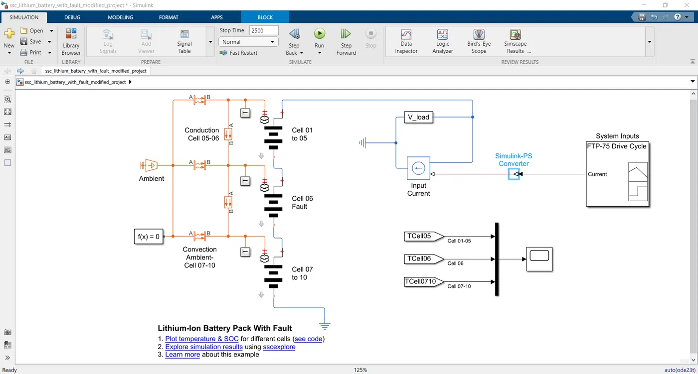
* Here we have added the FTP - Drive cycle load to the three battery packs as given in the above image.
FTP - 75 Drive cycle:
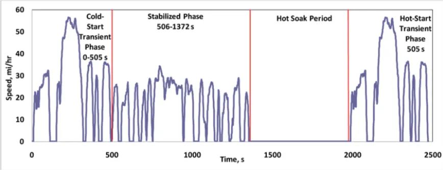
* The following are basic parameters of the cycle:
(i) Duration : 1874 seconds
(ii) Distance : 17.77 km
(iii) Average speed : 34.1 km/h
(iv) Maximum speed : 40.5 km/h
* The above Drive cycle has Time (seconds) vs Speed (Mph) as inputs and we cannot feed these data as the load reference for batteries.
* We can only send the current signals as inputs to the batteries and so we are doing this using a signal Builder Block.
* To know the effects of a electric vehicle battery's Temperature effects and state of charge we need to do the simulation through the steps given below,
1. Signal Builder block
↓
2. Simulink - PS Converter block
↓
3. Electrical Reference block
↓
4. Controlled current source block
↓
5. Voltage sensor block
Signal Builder block:
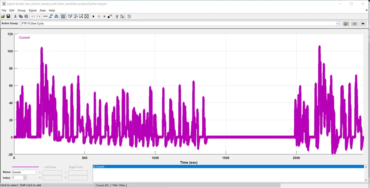
The signal builder block can only take the curent values as a input so the respective drive cycle data is changed to the current values and then fed as a input to the signal builder block.
* The above figure shows the value of the current with respect to time.
* Then we connect the signal builder which has the current signals with respect to time, to the Simulink to PS converter.
* The PS converter helps to establish connection between a simscape (Physical) model and a Simulink model and so the signals are converted.
* The current signals are now related to get the required voltage levels using voltage sensor block.
* Now we have the amount of potential difference that is required between the motor (Physical model) and the battery Terminals and this is the actual voltage load that the battery needs to fulfill based on the FTP - 75 Current signals.
* Now the Default simulation has been modified to have the battery packs supply the current based on the Drive cycle requirements and we can simulate the Temperature Effects and SOC of all three Battery packs.
Simulation and Results:
* The simulation is done with Three different Ambient Temperature Conditions and all the results and SOC results are Analysed and compared below.
Simulation 1 ( @ Normal Ambient Temperature) :
* The simulation is done for Analysing Temperature Effects on battery packs when connected to a FTP - 75 drive cycle Load.
The Total cycle time = 2500 seconds
All Battery packs Initial Temperature = 300 K = 26.8 Degree C
The Ambient Temperature = 300 k = 26.8 Degree C
Results:
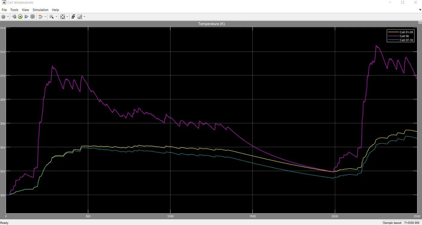
* In the Above plot there are three lines, the Yellow line indicates the Temperature of the First battery pack from cells (1 to 5) with respect to Time, Violet line indicates the Temperature of the second battery pack which has only one cell (6th cell) with respect to Time and the Green line indicates the Temperature of the Third battery pack from cells (7 to 10) with respect to Time.
* Based on the Drive cycle Requirements the current is supplied from the batteries and in the Drive cycle there are Two regions were the speed values go high slightly and inbetween these two High speed zones there is a Flat spot or Rest for some Time.
* Therefore the High speed region demands slightly higher power supply and so the Temperature of the battery packs rise and During the Rest region the Temperature actually drops.
* The first and Third Battery pack which has more number of cells and less internal resistance Heats up less compared to the second pack which has only one cell with slightly higher resistance which heats up More.
* In the first and Third battery packs During High speed regions of the drive cycle where more current Draw Happens, it goes to a maximum Temperature of 305 K which is nearly 32 Degree C, which we can say is quite bearable and it is not a unsafe Temperature zone.
* In those same condition of high current supply from the battery pack the second battery pack goes to maximum Temperature of 313 K which is equal to 40.2 Degree C, Which is quite a high temperature and is also not a safe temperature zone for operation of batteries as we may end up in a Thermal Runaway of the battery pack while on Use.
Simulation 2 ( @ Low Ambient Temperature) :
* The simulation is done for Analysing Temperature Effects on battery packs when connected to a FTP - 75 drive cycle Load.
The Total cycle time = 2500 seconds
All Battery packs Initial Temperature = 300 K = 26.8 Degree C
The Ambient Temperature = 288 k = 14.8 Degree C
Results:
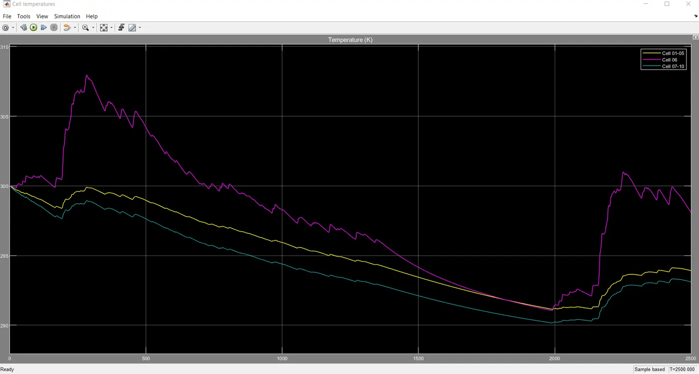
* In the Above plot there are three lines, the Yellow line indicates the Temperature of the First battery pack from cells (1 to 5) with respect to Time, Violet line indicates the Temperature of the second battery pack which has only one cell (6th cell) with respect to Time and the Green line indicates the Temperature of the Third battery pack from cells (7 to 10) with respect to Time.
* Based on the Drive cycle Requirements the current is supplied from the batteries and the simulation is done as same as before.
* The only change we have done is by lowering the Ambient Temperature further and monitor the Battery's Temperature behaviour over the usage.
* The High speed region demands slightly higher power supply and so the Temperature of the battery packs rise and During the Rest region the Temperature actually drops.
* The first and Third Battery pack which has more number of cells and less internal resistance Heats up less compared to the second pack which has only one cell with slightly higher resistance which heats up More.
* In the first and Third battery packs During High speed regions of the drive cycle where more current Draw Happens, it goes to a maximum Temperature of 300 K which is nearly 26.8 Degree C which is equal to the Intial Temperature of the three batteries.
* The temperature is observed to drops below the initial cell temperature after the usage and this is because of the Effect of Low Ambient temperature.
* As we have battery packs 1 and 3 at the outer surface of the battery pack case, the conductive and convective heat transfer takes place at the edges of the battery pack and so it is cool compared to the one on the centre of the battery pack which is battery pack 2.
* The second battery pack goes to maximum Temperature of 308 K which is equal to 34.8 Degree C, Which is a warm condition and also a safe temperature zone for operation of batteries while on Use. As the second battery pack is at the centre of the battery case there is less chance for it to get the ambient temperature that much as packs 1 and 3.
* Low ambient temperature plays a important role in the Temperature behaviour of battery packs.
Simulation 3 ( @ High Ambient Temperature) :
* The simulation is done for Analysing Temperature Effects on battery packs when connected to a FTP - 75 drive cycle Load.
The Total cycle time = 2500 seconds
All Battery packs Initial Temperature = 300 K = 26.8 Degree C
The Ambient Temperature = 315 k = 41.8 Degree C
Results:
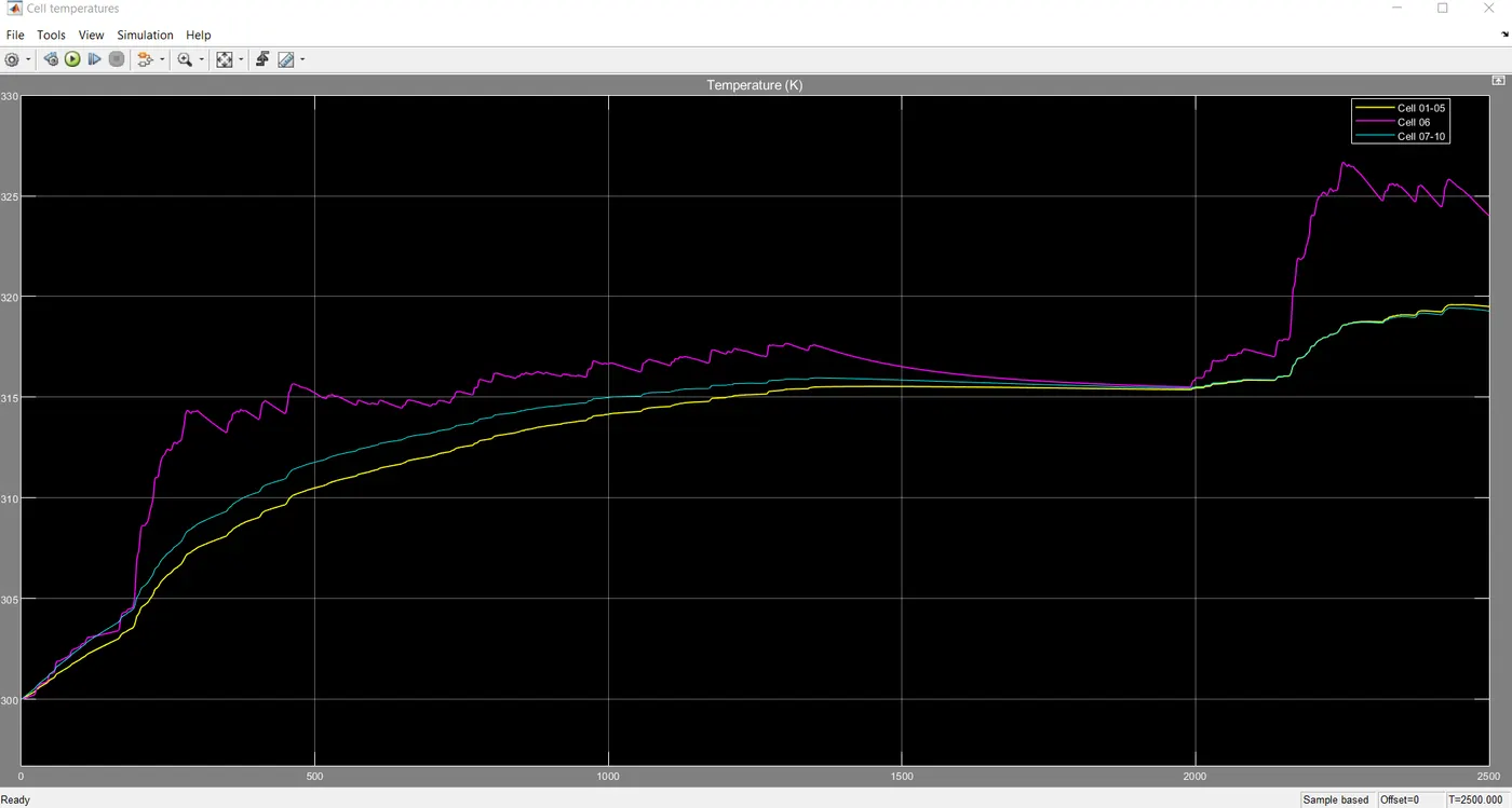
* In the Above plot there are three lines, the Yellow line indicates the Temperature of the First battery pack from cells (1 to 5) with respect to Time, Violet line indicates the Temperature of the second battery pack which has only one cell (6th cell) with respect to Time and the Green line indicates the Temperature of the Third battery pack from cells (7 to 10) with respect to Time.
* Based on the Drive cycle Requirements the current is supplied from the batteries and the simulation is done as same as before.
* The change we have done is by Incraesing the Ambient Temperature further and Study the Battery's Temperature behaviour over the usage.
* Based on the Drive cycle, in the High speed region demands slightly higher power supply and so the Temperature of the battery packs rise and During the Rest region the Temperature actually drops.
* The first and Third Battery pack which is palced in the edges of the battery case and also has more number of cells and less internal resistance Heats up less, compared to the second pack which is positioned at the centre of the battery case and also has only one cell with slightly higher resistance, heating up More.
* In the first and Third battery packs During High speed regions of the drive cycle where more current Draw Happens, it goes to a maximum Temperature of 320 K which is nearly 46.8 Degree C which is very high compared to the Intial Temperature of the cell.
* The temperature is observed to be very high because of the Effect of High Ambient temperature. As we have battery packs 1 and 3 at the outer surface of the battery pack case, the conductive and convective heat transfer takes place at the edges of the battery pack and so it is very Hot while on use.
* The second battery pack goes to maximum Temperature of 327 K which is equal to 53.8 Degree C, Which is a very Hot and also not at all a safe temperature zone for operation of batteries.
* As the second battery pack is at the centre of the battery case and also has only one cell with high internal resistance it becomes really very hot reaching an unsafe temperature region.
* Definitely while designing batteries to work under high ambient temperatures we need to design some effecting cooling system to keep the batteries Temperature in control and also to ensure safe operation of batteries.
* High ambient temperature also plays a important role in the Temperature behaviour of battery packs.
State of Charge of the Batteries:
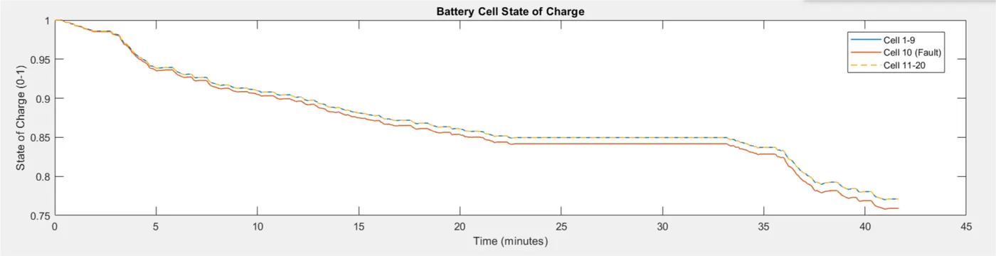
* For the above simulation we observe the state of charge for all the three battery packs through the above plot.
* We can see that the unstable battery pack 2 which suffers a lot of thermal problems results in draining of the battery in a much faster rate compared to the more thermally stable battery packs.
* From 100% of SOC the second battery pack After 42 Minutes of Usage seems to have less charge @ 75.5% compared to the other two battery packs which after the same usage of 42 minutes is slightly higher @ 78%.
* Therefore the Thermal stability plays a very important role in determining the usable capacity of the battery packs.
2. Cyclic Alternating Charge / Discharge:
* Now we are observing the battery's thermal behaviours over cyclic charging and discharging.
* This is also a Hard Test done for pushing the usable limits of the battery to a great extent so that we can Ensure the safe operation of the battery pack throughout its life span.

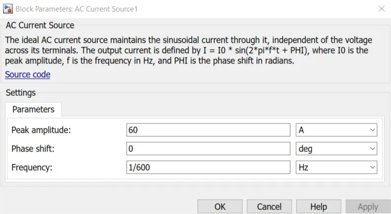
* An Alternating Current source is attached as the load to the battery and it charges the battery packs for some time and then Discharges the battery for some time and the process continious for a particular time at some frequency and Amplitude.
* We have changed the Amplitude of the current to 60 A and the frequency (i.e) the Number of positive and Negative cycle in a time period is given as 1/600 Hertz, which is so minimal.
* The In-Build model is modified as given below,
Simulation and Results:
* The simulation is done for Analysing Temperature Effects on battery packs when connected to a Alternating cyclic Charge / Discharge Load with the following parameters,
The Total cycle time = 7200 seconds
All Battery packs Initial Temperature = 300 K = 26.8 Degree C
The Ambient Temperature = 300 k = 26.8 Degree C
Results:
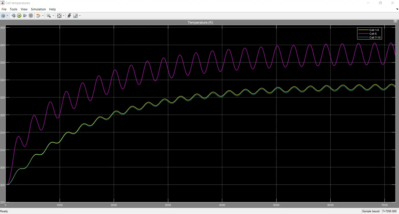
* In the Above plot there are three lines, the Yellow line indicates the Temperature of the First battery pack from cells (1 to 5) with respect to Time, Violet line indicates the Temperature of the second battery pack which has only one cell (6th cell) with respect to Time and the Green line indicates the Temperature of the Third battery pack from cells (7 to 10) with respect to Time.
* In this simulation we do a hard ensurance test on the battery packs by adding a AC Current source we are doing a Cyclic charging / Discharging over 2 Hours.
* The Temperature usually rises with every charging and discharging process and when it is repeatedly done the the Overall Temperature of the battery packs kept on increasing.
* The first and Third Battery pack which is palced in the edges of the battery case and also has more number of cells and less internal resistance Heats up less, compared to the second pack which is positioned at the centre of the battery case and also has only one cell with slightly higher resistance, heating up More.
* In the first and Third battery packs During cyclic charging / Discharging, it goes to a maximum Temperature of 329 K which is nearly 55.8 Degree C which is very high compared to the Intial Temperature of the cell which is 26.8 Degree C.
* The temperature is observed to be very high because of the Effect of constant charging and discharging.
* The second battery pack goes to maximum Temperature of 341 K which is equal to 67.85 Degree C, Which is Terribly Hot and also not at all a safe temperature zone for operation of batteries.
* As the second battery pack is at the centre of the battery case and also has only one cell with high internal resistance it becomes really very hot reaching an unsafe temperature region.
* Definitely while designing batteries considering this rare Phinomenon of cyclic charging and discharging over a long period of time, we need to design some effecting cooling system to keep the batteries Temperature in control and also to ensure safe operation of batteries.
* Thus Throught this Thermal modeling of battery pack by a Alternating current load Test, we have spotted the effects of High battery Temperature which could lead to a thermal runaway of the system and hence we need to rectify the problem.
State of Charge of the Batteries:
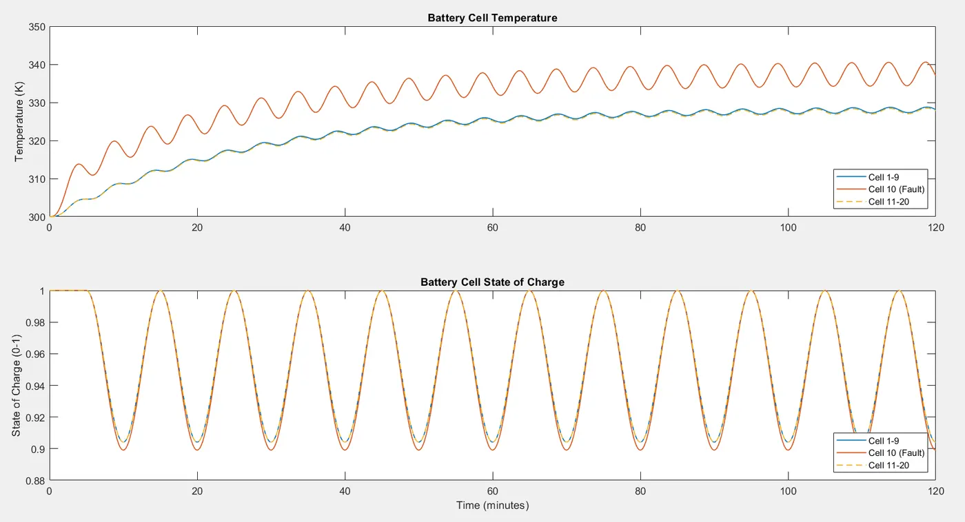
* Based on the cyclic load of charging / Discharging the SOC levels of all the battery packs responds.
* The SOC of all the battery packs from 100% fall to 90% and then they rise back to full charge levels and this is due the load of charge / discharge.
* The SOC observed at a particular time, for the first and third battery packs falls similar and compared to these two packs the second battery pack falls slightly more.
* This is all because of the high resistance and less open circuit voltage and capacity of the second battery pack.
Conclusion:
* Thus we can say the Thermal Modelling of a battery pack helps us a lot to ensure the safe operation of a battery packs in any system or Eectric vehicle application.
* In this simulation we have tested the battery pack's Temperature and SOC, with two types of load conditions like, Alternating current source which is a continious charge / discharge over a period of Time, and for an Electric vehicle application by modifying the available model to supply the current needs for a vehicle to run over a Drive cycle.
* This simulation helps us to avoid the risk of battery pack's high temperature effects and made us to observe the Temperature behaviour of batteries at different Extreme usage conditions. Also made us to observe the peak Temperature points which when not addressed with any alternate solution leads to a Thermal Runaway of the battery pack.
* The alternate way is by employing proper cooling system to the battery packs while using it on any kind of application to prevent the High battery temperature effects.
* Thus the Thermal Modelling of battery pack, evidently shows its Significance, that while developing any battery packs this process of simulation ensures the Safe operation and avoids Thermal Runaway to a great extent.