Project 2 Thermal modeling of battery pack
Thermal modelling of battery pack.
Objective:
For a 10-cell series lithium-ion battery model, simulate the thermal effects and compare life cycle performance at various temperatures, charge and discharge rates using MATLAB.
Introduction
The performance and life-cycle costs of electric vehicle (EV) and hybrid electric vehicle (HEV) depend inherently on energy storage system such ad batteries. Battery pack performance directly affects the all-electric range, power for acceleration, fuel economy, and charge acceptance during energy recovery from regeneration braking. Because the battery pack cost, durability, and life also affect the cost and reliability of the vehicle, any parameter that affects the battery pack must be optimized.
Temperature and temperature uniformity have a strong influence on battery pack performance and consequently, that of HEVs and EVs. All the modules in the pack should be operated within the optimum temperature range suitable for the particular electrochemical couple used. In addition, uneven temperature distribution in a pack leads to different charge/ discharge behaviour that results in unbalanced module and reduction pack performance. Because HEV batteries have high specific power and undergo aggressive HEV charging/ discharging profiles, thermal issuers in an HEV pack are of more concern than in EV packs.
In this project will simulate the thermal effect of a 10S1p lithium-ion battery pack, which consist of 10 ANR26650M1-B high-performance nanophosphate lithium iron phosphate (LIFePO4) battery technology delivers high power and energy density combined with excellent safety performance and extensive life cycling in a lighter weight, more compact package. To make its interesting, a fault has been introduced in one of the cells to demonstrate the effect of the faulty cell on the entire pack.
ANR26650M1-B nanophosphate lithium iron phosphate (LiFePO4) datasheet.
What is Faulty cell?
A faulty cell demonstrates performances that is different than the other cell usually most cell will be displaying the same SOC, temperature voltage level etc. but a faulty cell will show sign of overheating, faster discharge (due to reduced capacity or reduced OCV) will be unbalanced cell. This will be impacting the performance of the entries pack as the faulty cell will limit the pack from utilizing its maximum potential.
In this project the fault cell is representing by adding an extra external resistor. This makes the cell react differently than the other cells.
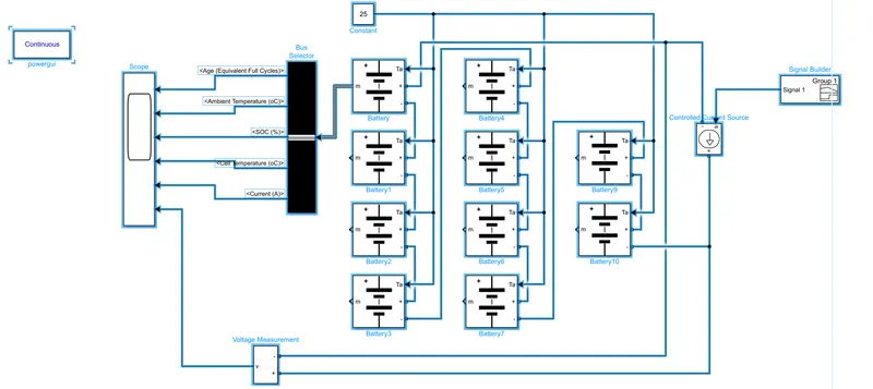
Simulink Model:
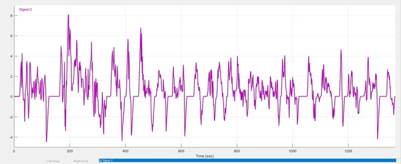
In this model 1st we give UDDS current profile to battery pack with help of signal builder block.
UDDS cycle (current vs time) has been used to charge discharge the batteries for given periode og time 1370 sec.
There is three modules has been connected together in series to make a 10 cell battery pack model.
In cell No. 6 artesistor can be added to vary the rate of discharge.
All cell are configure same as ANR26650M1-B cell. It means put same value which in datasheet.
All cell are initially at 25 degree c.a.temp.source is used to test the cell performance at 3 different atm. Temperature, like at 25 degree C, at 45 degree C, at -10 degree C.
Convective and conductive block has been added for heat transfer between blocks.
Vehicle current model:
In vehicle current requirement subsystem block, the signal builder block used to apply UDDS current profile and Simulink-PS converter block used to convert the Simulink signal to physical signal connecting port block used to output the signal.
Controlled current source
The controlled current source block converts the Simulink input signal into an equivalent current source. The generated current is driven by the input signal of the block. The positive current direction is as shown by the arrow in the block icon. We can initialize the controlled current source block with a specific AC or DC current. If you want to start the simulation in steady state, the block input must be connected to a signal starting as a sinusoidal or DC waveform corresponding to the initial values. For this model I used the default value.
Generic battery:
The battery block implements a generic dynamic model that represents most popular types of rechargeable batteries. For this model enable the temperature effects and aging effects options. So cell nominal voltage is 7.2 V, capacity 5.4Ah, initial SOC 100% , in aging section aging model sample time is 20 sec, aging characteristic at cell ambient temperature of cell 25 degree C and nomial charge and discharge current value take as variable, which is similar to the input current signl. And asll other parameters are default values. So now our battery pack voltage is 72 V and capacity is 5.4 Ah.
So all these blocks are connected as per shown in the above model figure. And this model runs for 100 sec.