Project 2 - Speed Control of a Direct Current (DC) motor
In this project we are using a separately excited DC motor whose speed is to be controlled by using a PID controller. First we understand how a DC motor speed control can be achieved, Dc motor speed control can be achieved by controlling the armature voltage and the field flux. But in our project we are not going to change the field flux so, only by varying the armature voltage we will try to achieve our goal. In our example we first determined the motor parameter.
-
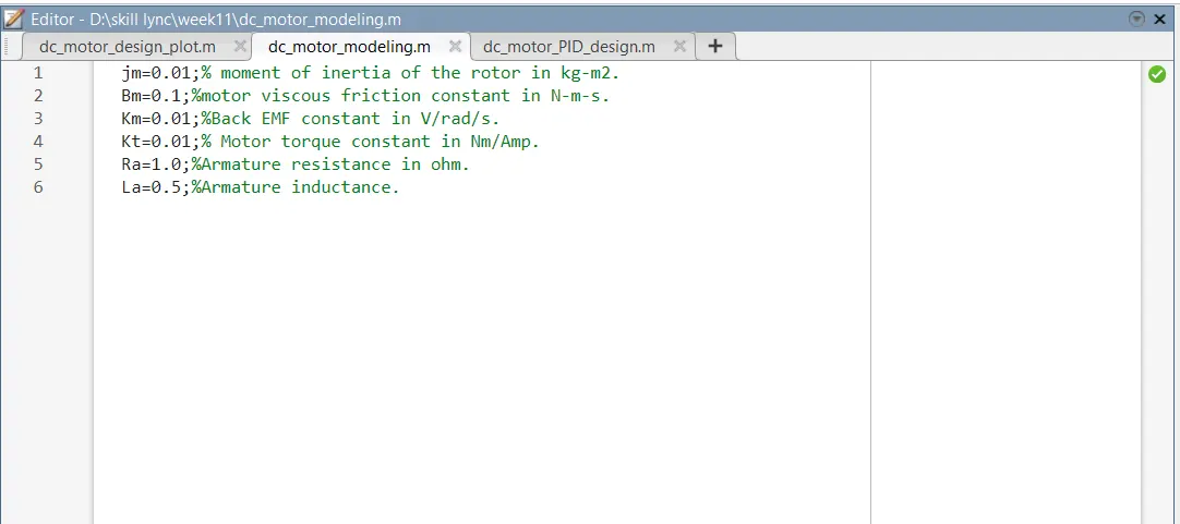
Moment of inertia of the rotor (jm) =0.01( kg.m^2.);
-
Motor viscous friction constant(Bm) =0.1(N.m.s);
-
Back EMF constant(Km) =0.01(V/rad/sec);
-
Motor torque constant(Kt)=0.01(N.m/amp);
-
Armature resistance(Ra)=1 ohm.
-
Armature inductance(La)=0.5 H.
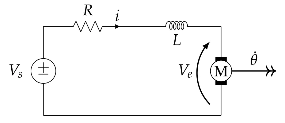
As we previously said, we keep field excitation constant so that part can be eliminated from the model. So, firstly we will find the armature current as per the reference voltage. As, per Kirchhoff’s closed loop law -
L(dI/dt)+RI=V-Kb(d Theta/dt)
Converting above equation to’s’ domain(Laplace transform)
Ls I(s)+ RI(s) = V(s) - Kb s theta(s);
I(s)=V(s)-Kb s theta (s)/L s + R;
Using this equation we will find the armature current then if we multiply the armature current with ‘motor torque constant’ we will get the motor torque the equation is-
T=Kt*I;
Now, for finding the motor speed we have to multiply the motor torque with motor mechanical property, as per newton’s law-
J(d theta^2/dt^2)+B(d theta/dt) = Kt * I;
Converting it to ‘s’ domain(Laplace transform)
J s^2 theta(s) + B s theta(s) = Kt * I(s);
w(s)= s theta(s) = Kt *I(s)/ J s + B ;
so, the motor model is made in the simulink-
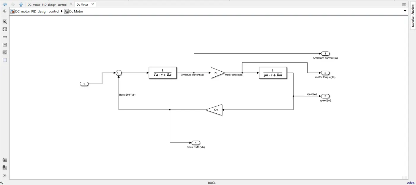
from this model we get the output of -armature current, motor torque, speed of the motor, and back EMF.
DC motor modeling parameter set in matlab programming:
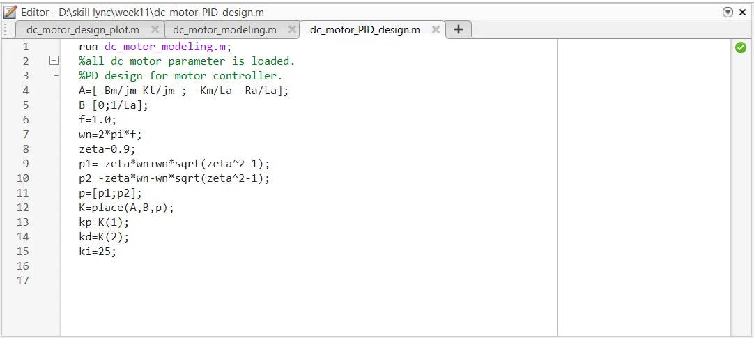
Now, we will design a PID controller to control the speed of the motor. so, for that first we have to find the design parameter like A,B matrics and then we have to find the poles of the system. so, for finding the poles of the system first we have to put the the 'Zeta' value and the natural frequency of the system 'fn' . then from the natural frequency
p1=-zeta*wn+wn*sqrt(zeta^2-1);
p2=-zeta*wn-wn*sqrt(zeta^2-1);
then, we put the p1 and p2 value in 'p' matrix- p=[p1;p2];
then using 'place' commend in matlab we get the value of 'K'.
from their we get to know about the 'proportional constant' and the 'derivative constant' kp and kd.
PID controller programming in MATLAB is given below-
then we go to the PID controller model in simulink, simulink model is given below with a DC motor model.
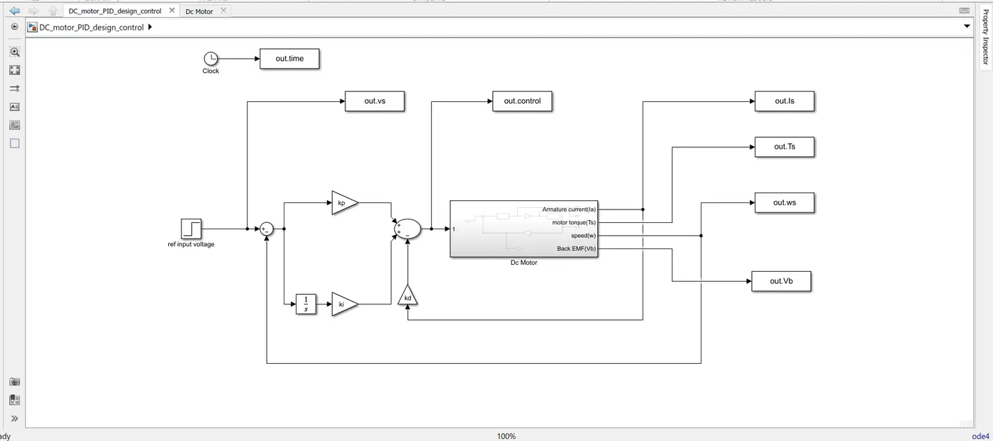
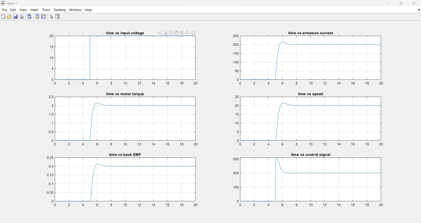
so, all the modeling part is completed so, now we will observe the output of the system. first we will observe the out put from reference input voltage 0v to 20v then we will increase the speed of the motor by varying the voltage 20v to 50v. wave from is shown below-
from 0v to 20v:
now, we increase the voltage from 20v to 50v:
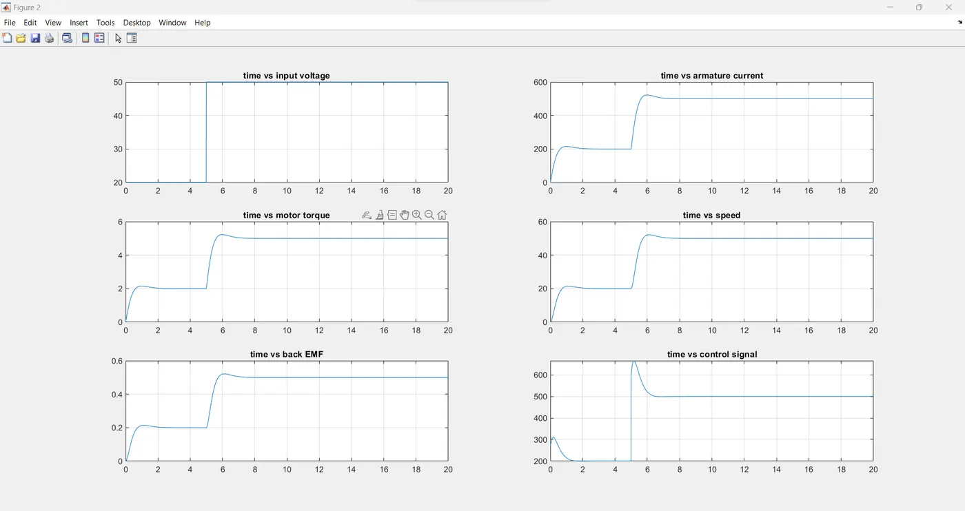
so, from the wave from we can observe that with PID controller we are getting a very control out put setteling time is around 2s and overshoot is less than 5% and steady state error is almost zero.
this is how we model a DC motor with said parameter and a PID controller to get control output.