Project - 2 - Meshing on the suspension Assembly
Aim:- Meshing on the suspension Assembly
Objective:-
- Check for the geometrical errors.
- Mesh with the given element Quality Criteria. After meshing assign the component thickness to mid surface.
- Use tetra elements to model non unifrom thickness.
- Use appropriate connections to connect the component.
- Perform symmetry command to reflect the half finshed model to the other side.
Quality Criteria for Surface Meshing of Tyre and Rim (Element type: Tria) :
|
S.No |
Quality Criteria |
Value |
|
1 |
Target/Average length |
6.5 |
|
2 |
Minimum Length |
5 |
|
3 |
Maximum Length |
10 |
|
4 |
Skewness |
45 |
Quality criteria for Surface Meshing of Non Uniform thickness components other than Tyre and Rim (Element type: Tria) :
|
S.No |
Quality Criteria |
Value |
|
1 |
Target/Average length |
4 |
|
2 |
Minimum Length |
2 |
|
3 |
Maximum Length |
6 |
|
4 |
Skewness |
45 |
Quality Criteria for Volume meshing of all Non Uniform thickness components (Element type: Tetra Elements):
|
S.No |
Quality Criteria |
Value |
|
1 |
Tet-collapse |
0.2 |
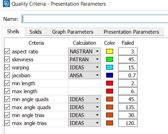
Quality criteria for Mid surfacing of Uniform thickness part which has thickness less than 5 mm (Element type: Mixed elements) :
|
S.No |
Quality Criteria |
Value |
|
1 |
Target/Average length |
4 |
|
2 |
Minimum Length |
2 |
|
3 |
Maximum Length |
6 |
|
4 |
Aspect |
3 |
|
5 |
Warpage |
15 |
|
6 |
Skewness |
45 |
|
7 |
Jacobian |
0.7 |
|
8 |
Minimum Quad Angle |
45 |
|
9 |
Maximum Quad Angle |
135 |
|
10 |
Minimum Tria Angle |
30 |
|
11 |
Maximum Tria Angle |
120 |
PROCEDURE:-
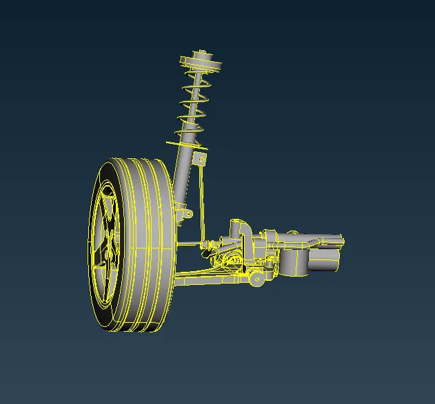
Step-1:- First import the CAD model into ANSA.
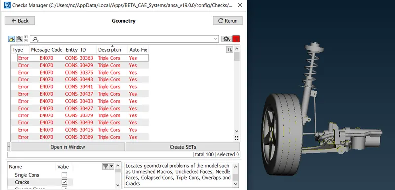
Step-2:- Check Geometrical Errors
- Once the topo action is done, the model is checked for geometrical errors, any error shown in the model need to be fixed.
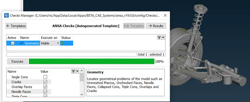
- Model after fixing all the geometrical issues.
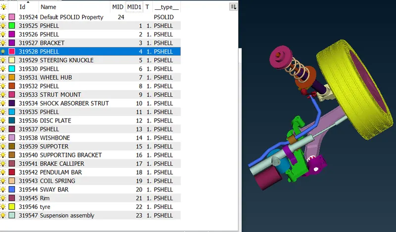
- Now assign the PID for each component so it will be easy to perform the midsurafcing and meshing. Assign the PIDs go to topo>faces>set PID.
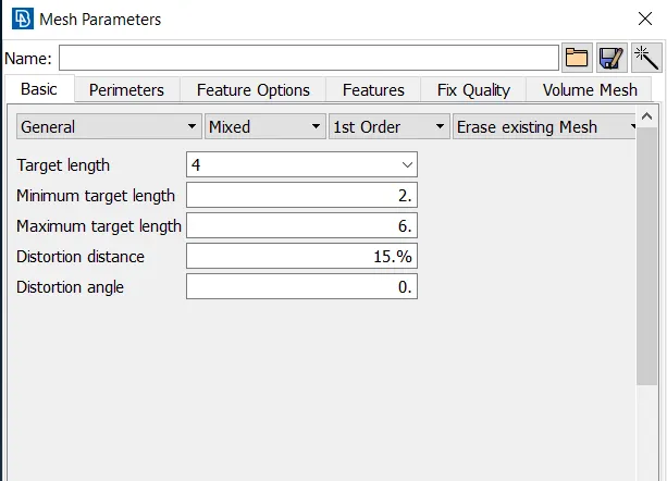
- First assign the quality criteria and mesh parameter.
SHELL MESHING:-
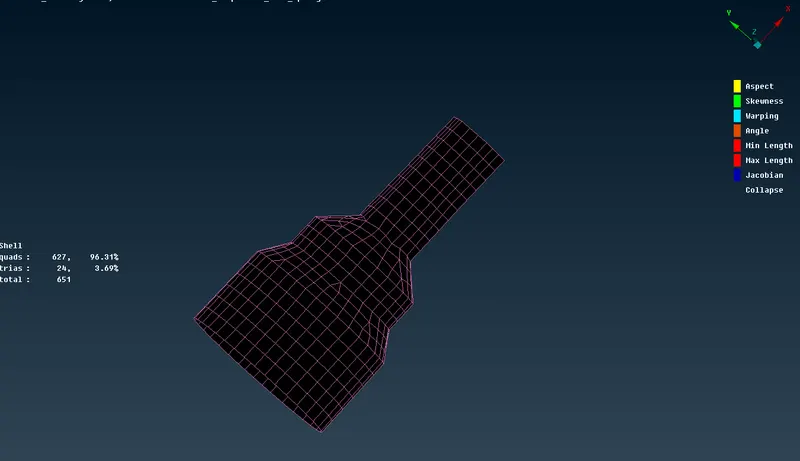
- We have set the perimeter length and macro length. Mesh module>perimeter length>macro length>enter value.
- For the following component i used casting method as the components are not complex. Topo module>Faces>Midsurface>Casting.
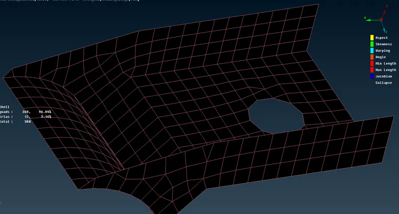
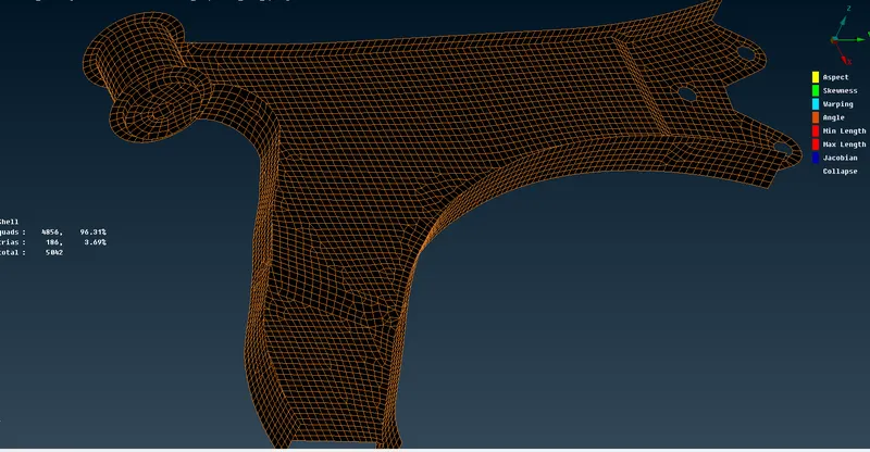
- All the components are done with the same method.
VOLUME MESH:-
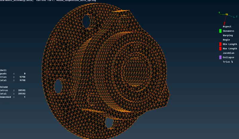
- Before performing volume mesh we have to do shell mesh on the surface of the componenets.
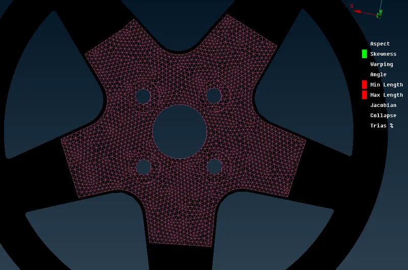
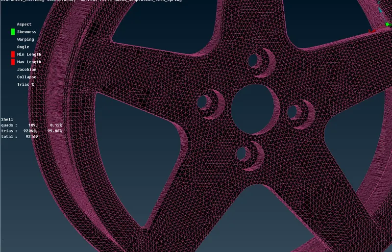
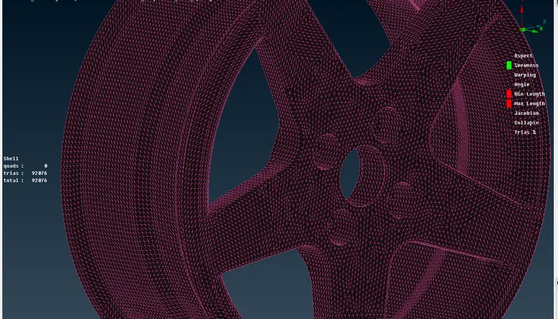
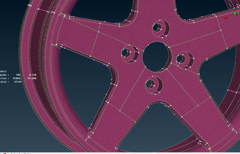
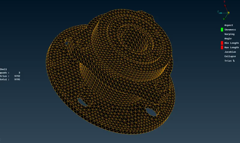
- We are using two types of trias ortho tria and normal trais.
- Ortho trais are used on the curved surface and normal trias are used on the flate surface.
- Ortho trias will capture the fillets and holes without any kind of kinks and raised edges.
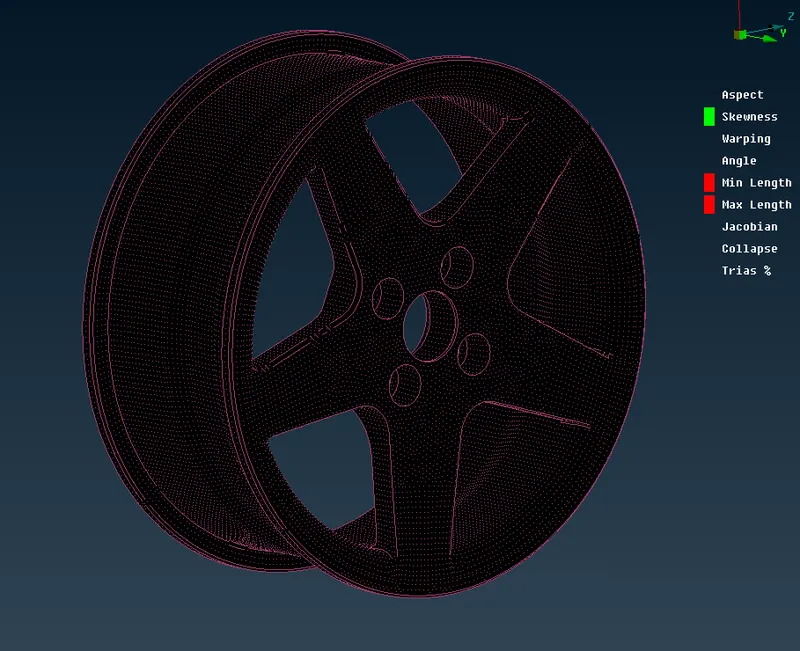
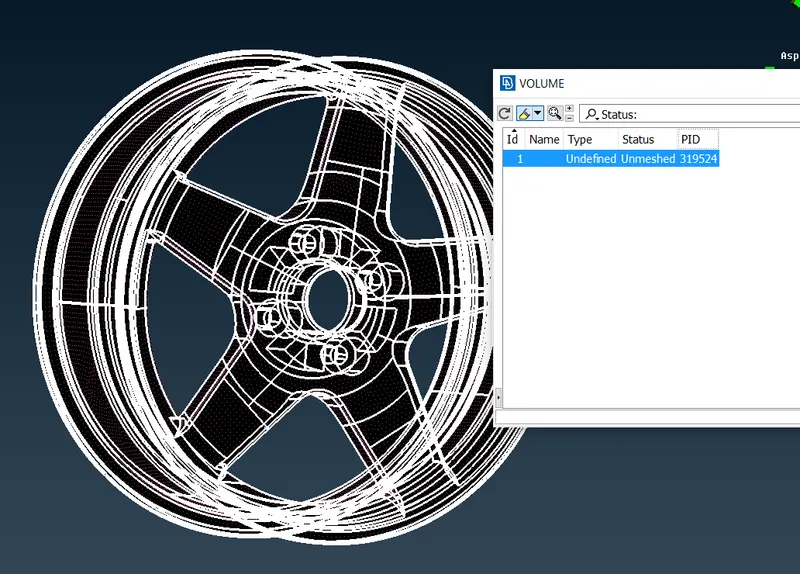
- To perform the volume mesh we have to define it add it to the list.
- After that we can move to the list right click then it will ask the mesh to Tetra Rapid or Tetra FEM.
- After meshing we have to check the quality if any element is failing for the tet collapse.
- Then we have to manually clear the tet collapse.
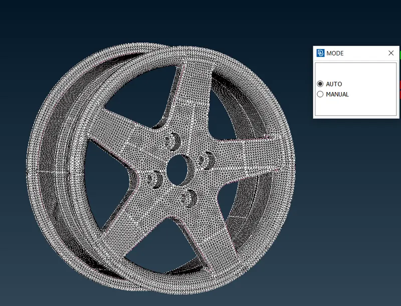
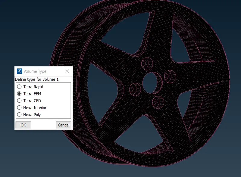
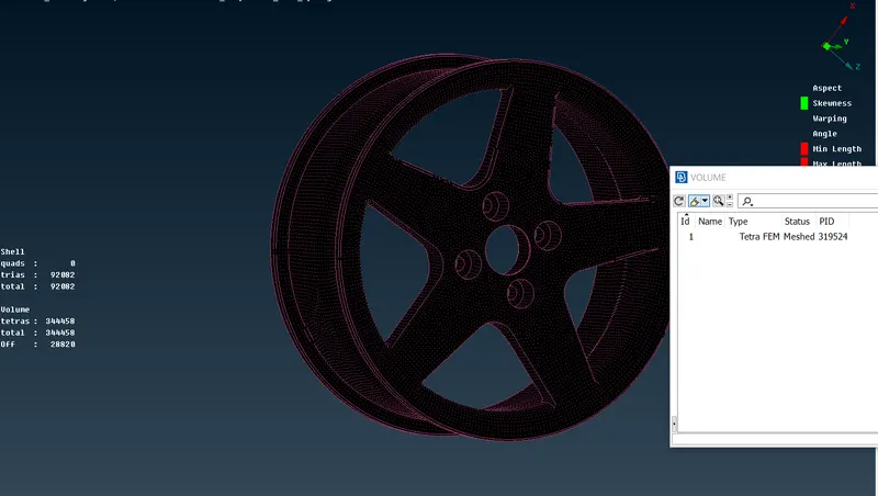
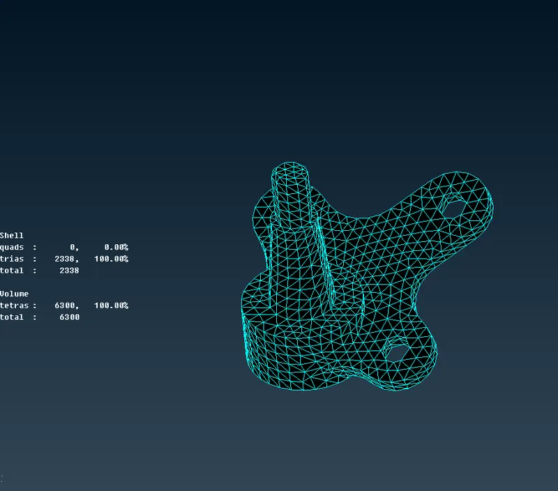
- Finally, Volume Mesh is generated.
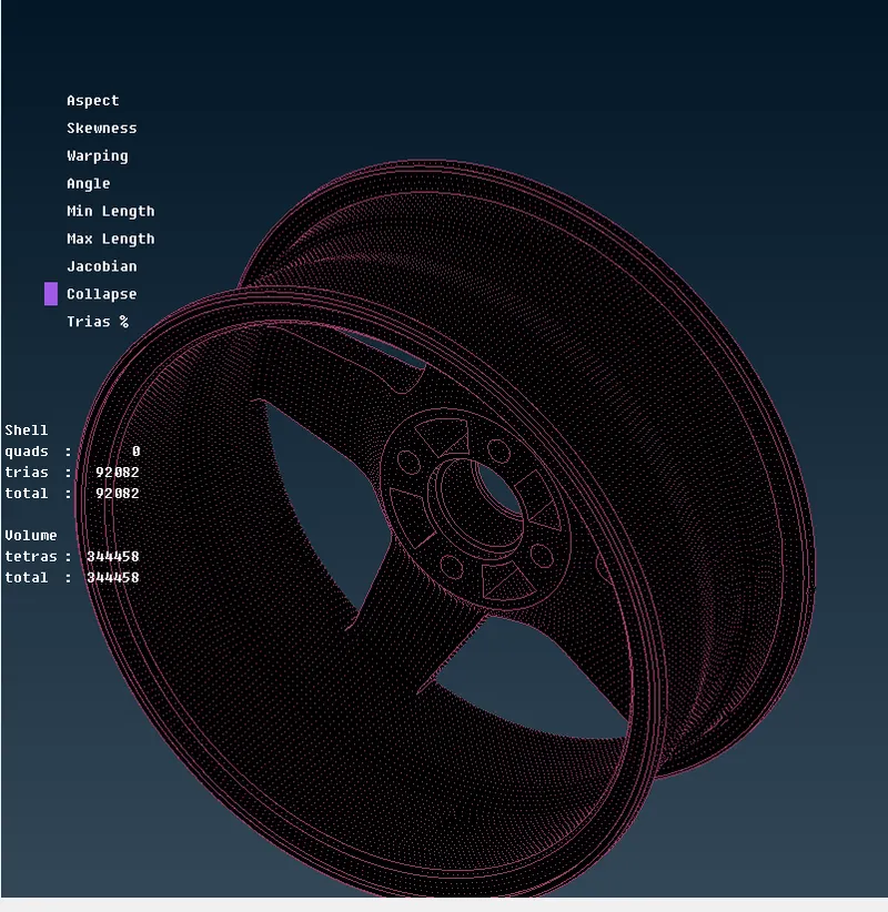
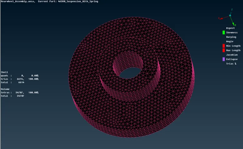
- FOLLOW SAME PROCESS FOR TYRE.
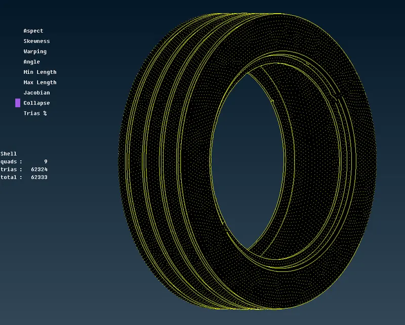
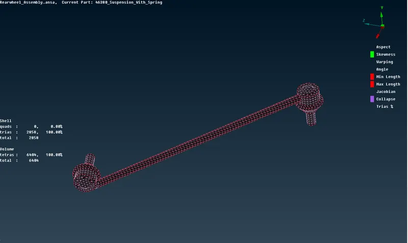
- Now the volume mesh is done we will go for the non uniform thickness surface meshing for that we will use spot mesh and after the surface meshing is done we will perform volume meshing on those components.
RBE2 CONNECTION:-
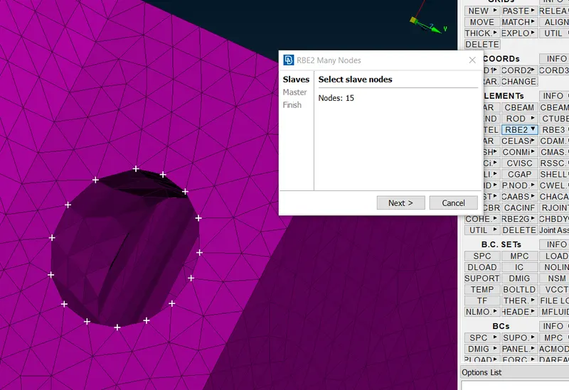
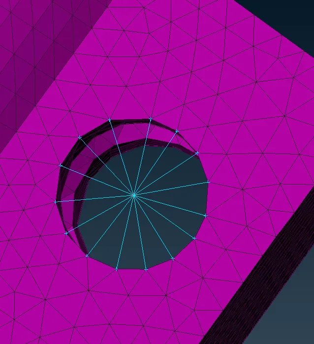
- Now next is connection part, for connection we will be doing rigid connection for that we have go to Nastran Module for performing the connection operation.
- First we will perfom the RBE2 multi nodes connection for that go to ELEMENTS>RBE2>MULTI and select the nodes as shown below image-
SYMMETRY OPERATION :-
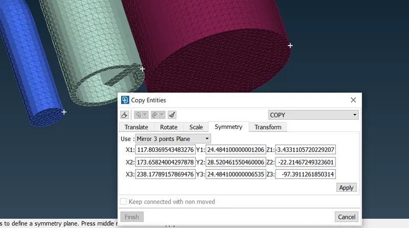
- For that go to Transform>Copy>Entities from utilities module and then select the entire component as shown below image-
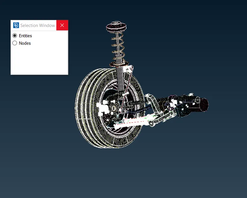
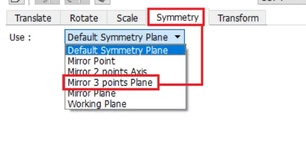
- After that go to Symmetry Operation and select the Mirror 3 Points Plane and than select the points as shown in below image.
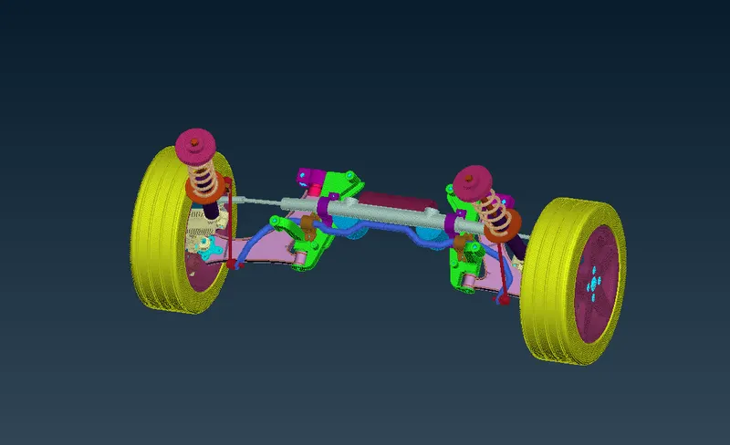
- This is how the actual component will looks like.
LEARNING OUTCOME:-
- Assign proper PIDs for each component.
- Able to generate midsurface and volume mesh.
- Perform the RBE2 connection properly.
- Learn how to perform symmetry operation.
CONCLUSION:-
The component of rear suspension system are captured with solid elements (tetra) and shell elements.The volume mesh is generated properly where required. All the area captured with the tria element.