Project - 2 - Meshing on the suspension Assembly
AIM: Meshing and implementing connections to the car rear suspension model.
ABSTRACT: In this project, I have taken a half section of a car rear suspension system where I will perform meshing on different components with 3D, 2D & 1D elements. Also, I will implement the connections to the areas required. The components with a uniform thickness of less than 5 mm are captured by the mid-surface technique (2D-elements), spring with 1D elements, and rest are captured using 3D elements(Tetra elements).
METHODOLOGY: To capture the geometry we need to follow these steps.
- Import geometry & Topological cleanup
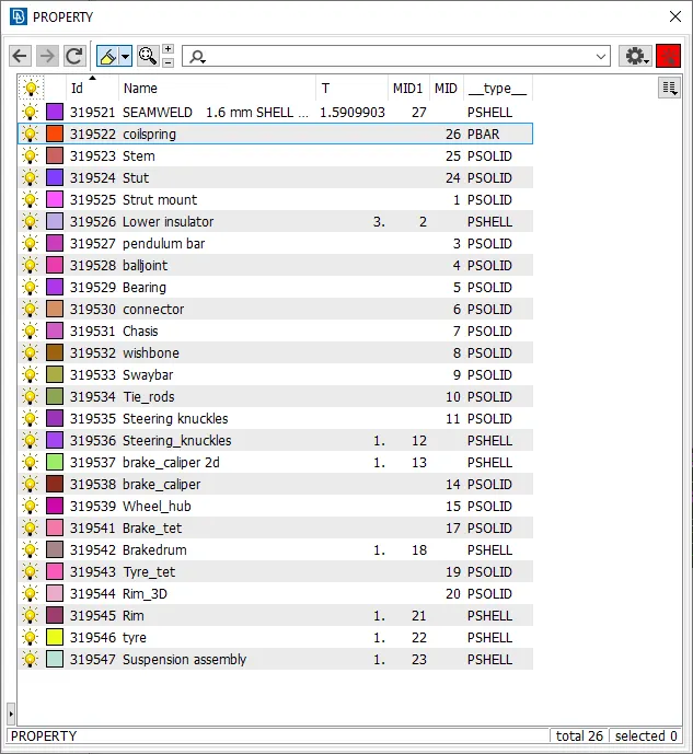
- Parts segregation under different property ID
- Quality parameter and Mesh parameter setup as per the requirements given
- Construction line adjustment and defeaturing
- Mid-surface extraction if the components with a uniform thickness of less than 5 mm
- Shell meshing and mesh correction.
- Volume definition and 3D mesh generation for other than mid-surfaced components.
- Implementation of connections at required areas.
QUALITY PARAMETERS:
These are the following quality criterion required to be followed in this project:
Quality Criteria for Surface Meshing of Tyre and Rim (Element type: Tria) :
|
S.No |
Quality Criteria |
Value |
|
1 |
Target/Average length |
6.5 |
|
2 |
Minimum Length |
5 |
|
3 |
Maximum Length |
10 |
|
4 |
Skewness |
45 |
Quality criteria for Surface Meshing of Non-Uniform thickness components other than Tyre and Rim (Element type: Tria) :
|
S.No |
Quality Criteria |
Value |
|
1 |
Target/Average length |
4 |
|
2 |
Minimum Length |
2 |
|
3 |
Maximum Length |
6 |
|
4 |
Skewness |
45 |
Quality Criteria for Volume meshing of all Non-Uniform thickness components (Element type: Tetra Elements):
|
S.No |
Quality Criteria |
Value |
|
1 |
Tet-collapse |
0.2 |
Quality criteria for Mid surfacing of Uniform thickness part which has thickness less than 5 mm (Element type: Mixed elements) :
|
S.No |
Quality Criteria |
Value |
|
1 |
Target/Average length |
4 |
|
2 |
Minimum Length |
2 |
|
3 |
Maximum Length |
6 |
|
4 |
Aspect |
3 |
|
5 |
Warpage |
15 |
|
6 |
Skewness |
45 |
|
7 |
Jacobian |
0.7 |
|
8 |
Minimum Quad Angle |
45 |
|
9 |
Maximum Quad Angle |
135 |
|
10 |
Minimum Tria Angle |
30 |
|
11 |
Maximum Tria Angle |
120 |
PROCEDURE:
Import geometry & Topological cleanup
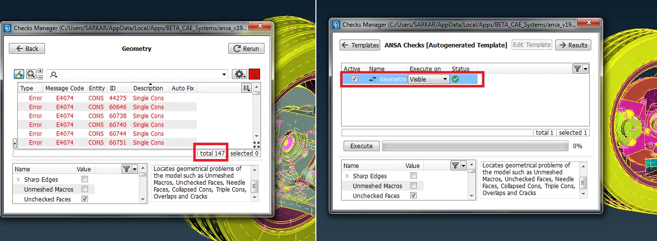
First of all, we need to import the CAD model into the ANSA interface. Once we are done loading the file do a TOPO over the full geometry. Then go for a geometry check and fix all the topological errors to proceed to the next step.
Parts segregation under different property ID
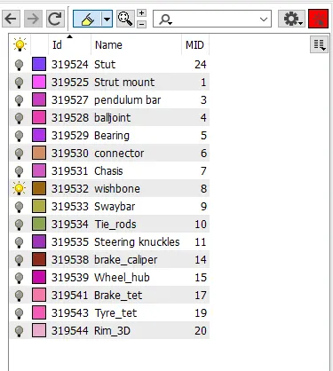
Once we have fixed all errors we can segregate different parts under property ID so as to proceed part by part which helps to expedite the process of pre-processing
Quality parameter and Mesh parameter setup as per the requirements given
Shell meshing and mesh correction.
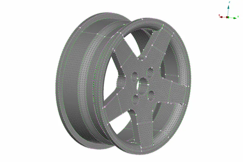
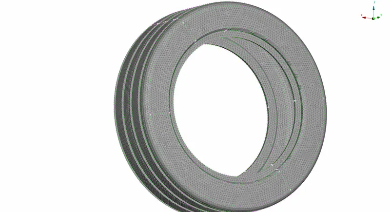
1) Tire and Rim
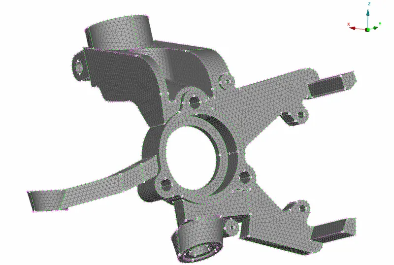
2) steering knuckle
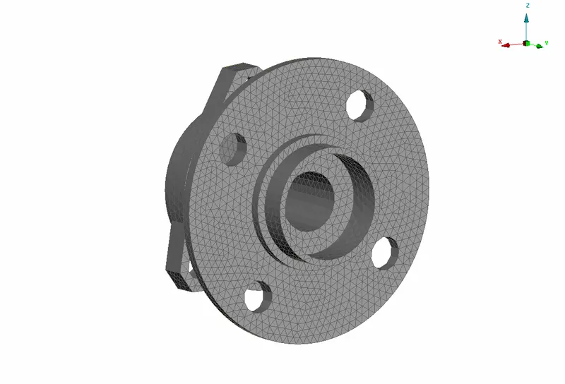
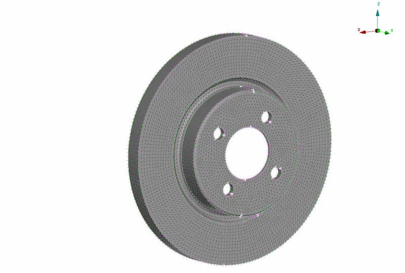
3) Wheel Hub and Brake Disc
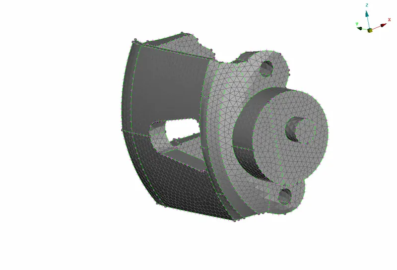
4) Brake caliper
5) shock absorber and pendulum bar
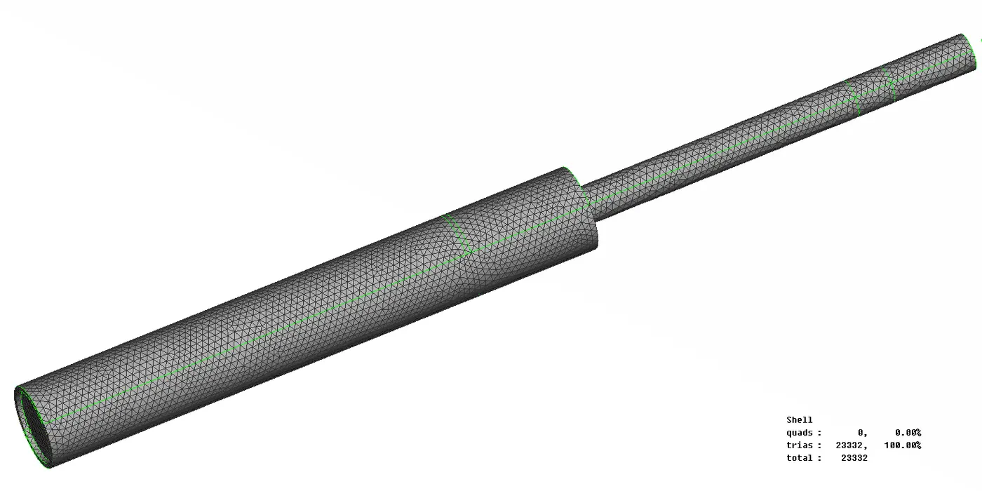
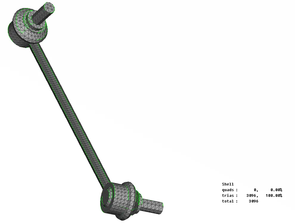
6) wishbone and Car frame
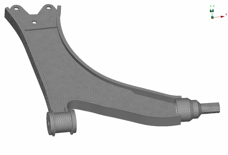
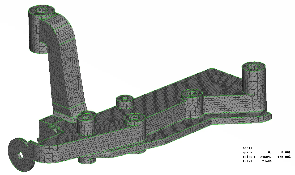
Volume definition and 3D mesh generation for other than mid-surfaced components.
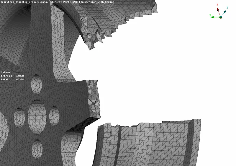
The next step we need to do is define their volume and generated Tetra elements through the volume but before defining them on the list we need to make sure the part is properly meshed and closed. Also, the part should not contain any overlapping surface. Define them one by one and set different PID type Solid as shown below figure. I have used Rapid Tetra mesh algorithm to auto-generate the Tetra element inside the volume.
There are some section view illustrating Tetra solid element inside the volume
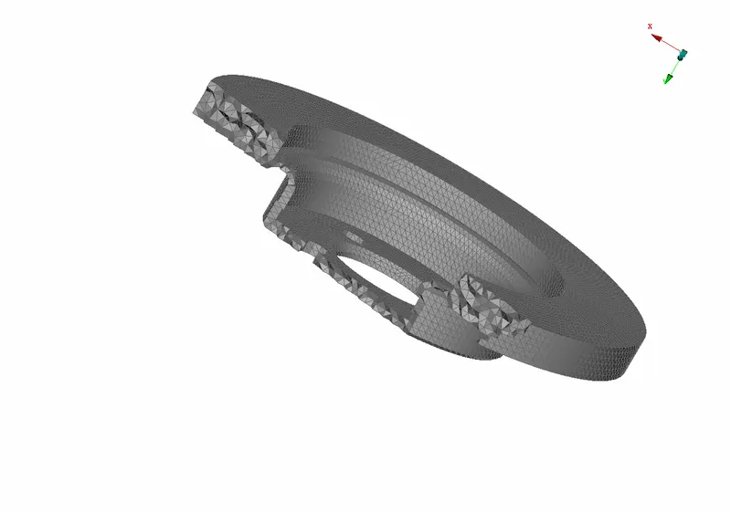
Shell Mesh
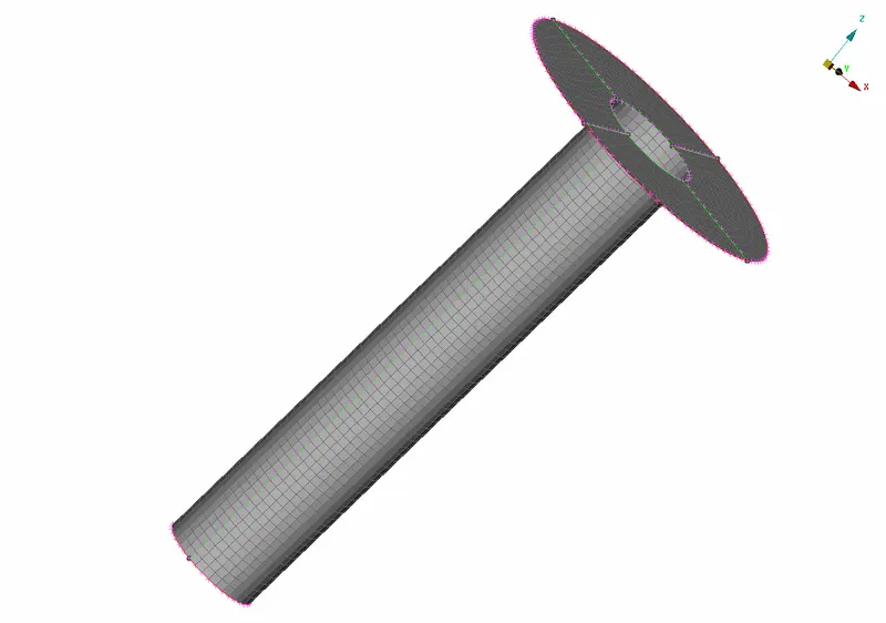
CONNECTIONS
BOLT-RBE2
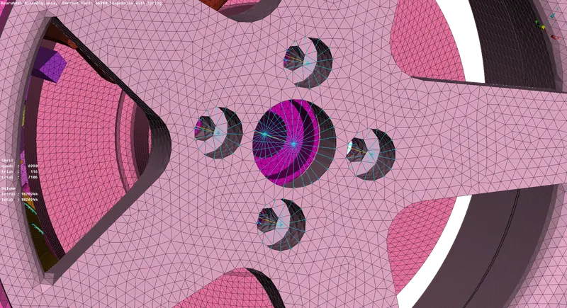
Seamweld
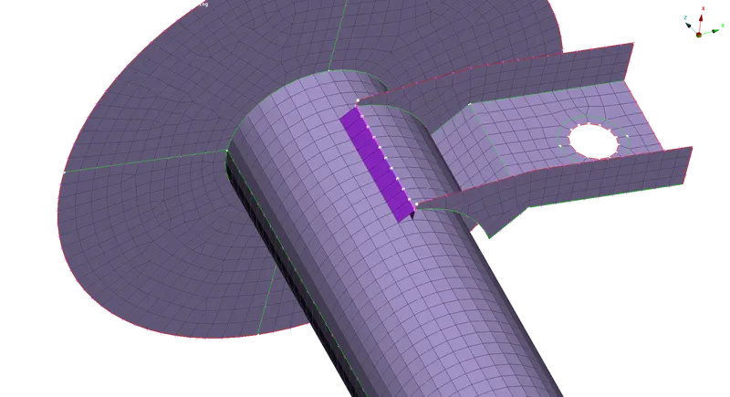
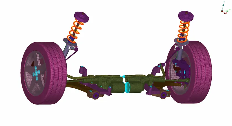
FINAL RESULT
so finally we have completed the meshing process, connection and get the final model as shown below
Learning outcomes:
- Fixed the geometrical errors in Ansa manually.
- Learned to extract the mid surface for the component.
- Got the idea to assign the property and material specification to the component.
- Studied to do meshing according to the quality criteria.
- Learned to use Volume mesh and understood the facts behind Tetra FEM and Tetra Rapid
- Studied structural and un-structural mesh.
- Learned to remove the tetra collapse from the volume mesh and studied to move kinks or raised dips from the volume mesh
- Studied different types of connections and respective steps to do it in connection manager options (automatic connection) and also to deploy connections manually
- Two Node RBE2 - Used to represent the stem of a bolt
- Many Node RBE2 - Represents the Rigid connections/cluster representation
- Used the transform option to do meshing effectively and saved much time.