Project - 2 - Meshing on the suspension Assembly
Project 2
AIM:-
For the given model, Need to Take the mid surface when the thickness is uniform and less than 5 mm & all other components need to perform volume mesh after checking the geometrical errors and mesh the mid surface with the given element Quality criteria.
Steps that are to be followed before meshing: -
• Initially we need to check the geometry and whether it is properly the surfaces are stitched/attached or not.
• Check the geometry errors for the component as mentioned property card.
• Clear the geometry errors that are found during checking for an individual property.
• After checking the geometry check-up, we need to check the thickness for property individually for every part that has been given.
• Subsequently we need to provide/assign mesh properties i.e., maximum length & minimum length.
• The next step that needs to perfume is giving the quality criteria that have been provided as per requirement.
• After checking quality, we need to assign perimeter length/macro length in property mode in classic mode.
• Now finally mesh procedure comes into the picture & certain steps to be taken into consideration i.e. eliminating opp trias,trias touching to feature line need to eliminate …etc.
• For the entire we need to assign different quality criteria as mentioned in the model.
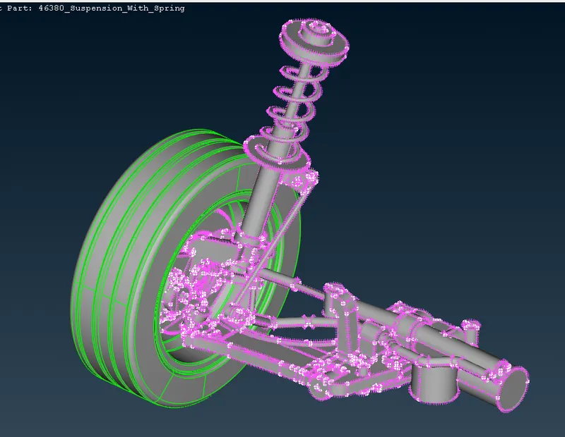
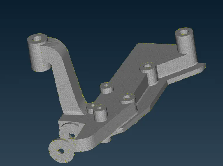
The total component assigned is shown in the below capture.
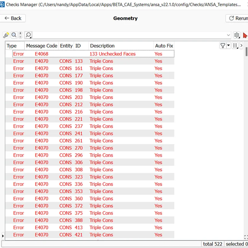
Quality errors that have rectified for the given model.
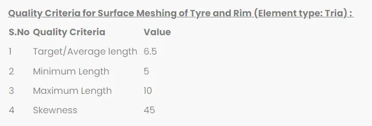
Quality criteria are given for the model into 3 categories shown below.
1.
2.
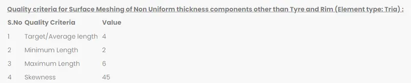

3.
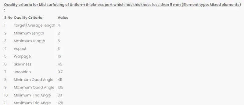
following tips to be implemented for the given model.

- Whole components are divided into 11 parts for better meshing with different PIDs
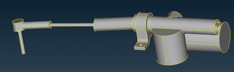
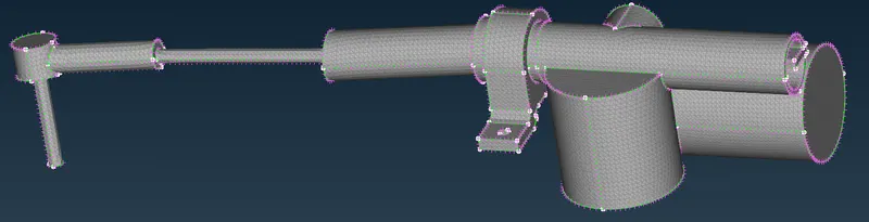
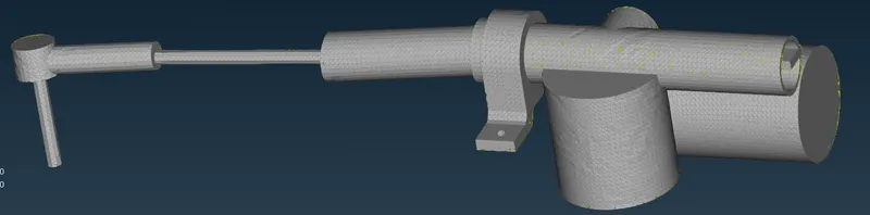
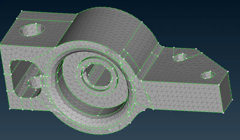
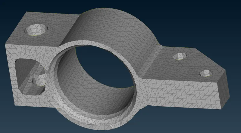
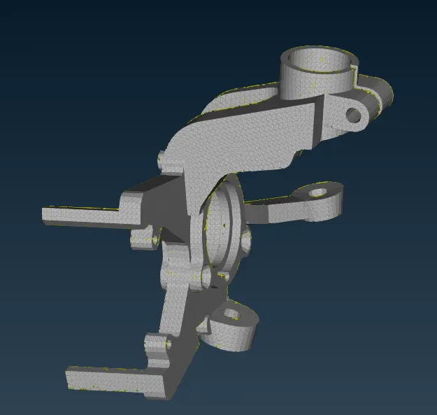
The below captures represent PID, shell mesh & Volume mesh for every individual parts.
Part 1:-
PID
2D mesh
Volume mesh
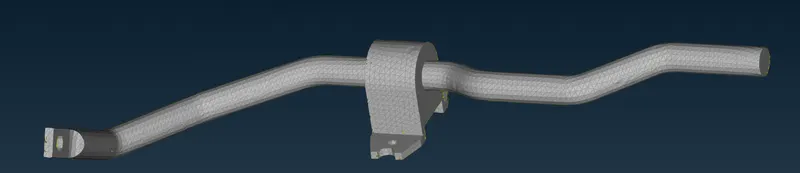
Part 2:-
PID

2D mesh
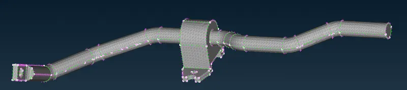
volume mesh
Part 3:-
PID
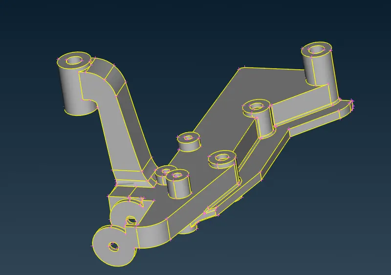
2D mesh
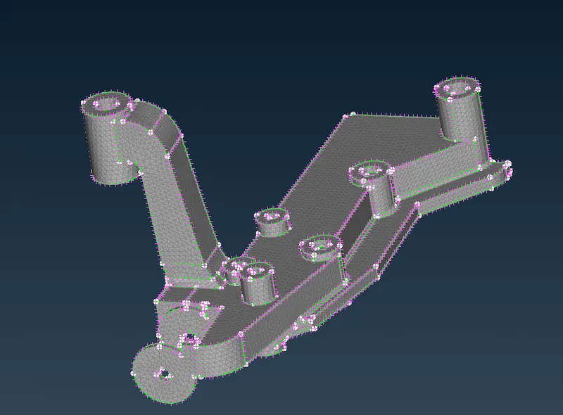
volume Mesh:-
Part 4:-
PID
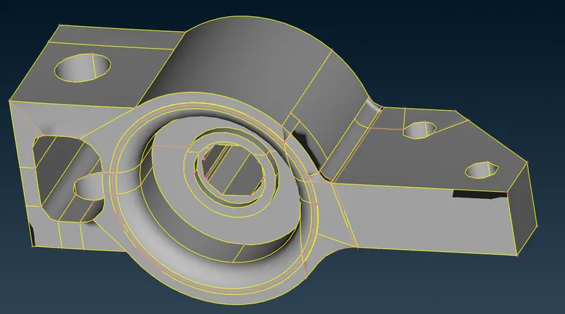
2D mesh
volume mesh
Part 5:-
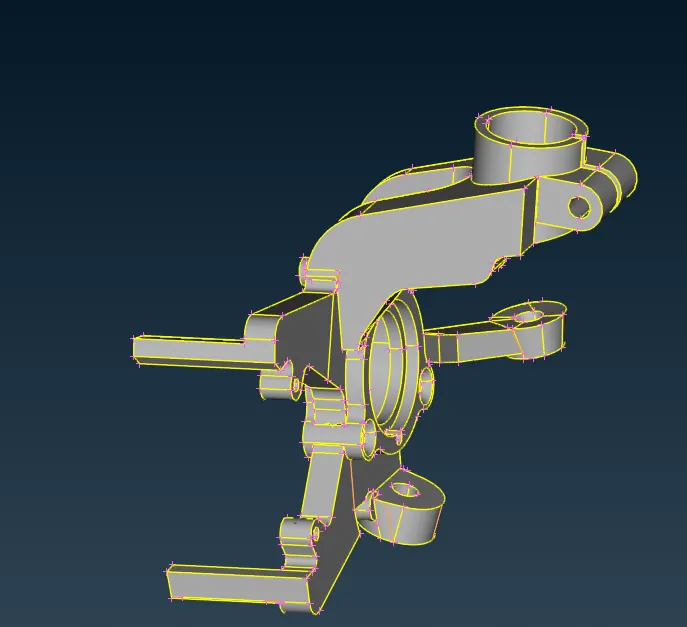
2D mesh
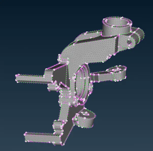
volume mesh
Part 6:-
PID
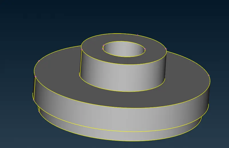
2d mesh
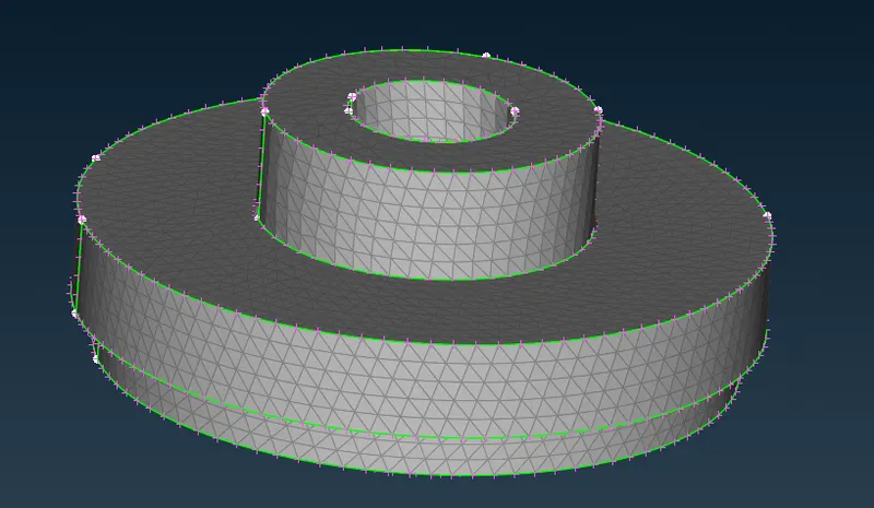
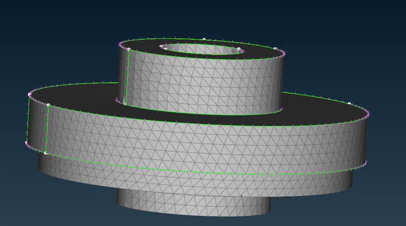
Part 7:-
PID
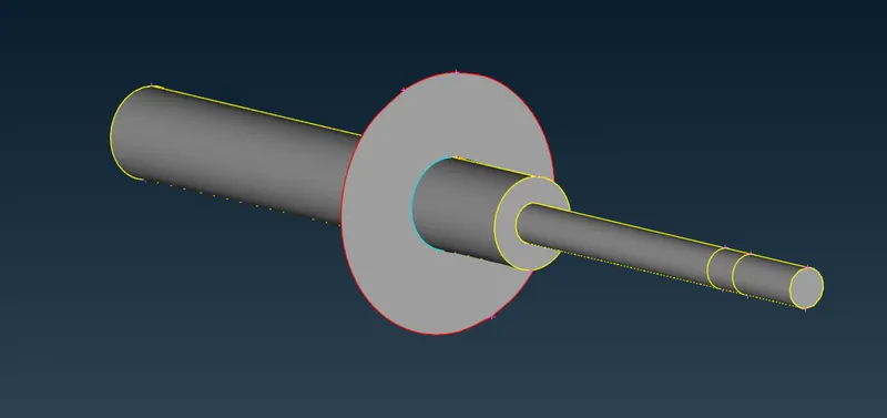
2D mesh
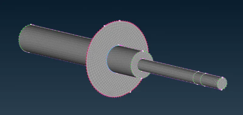
volume mesh
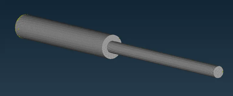
Part 8:-
PID
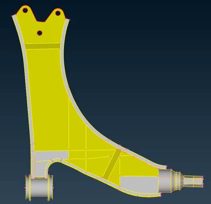
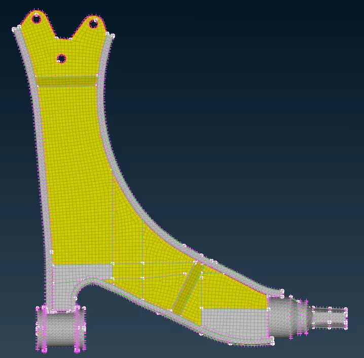
2D mesh
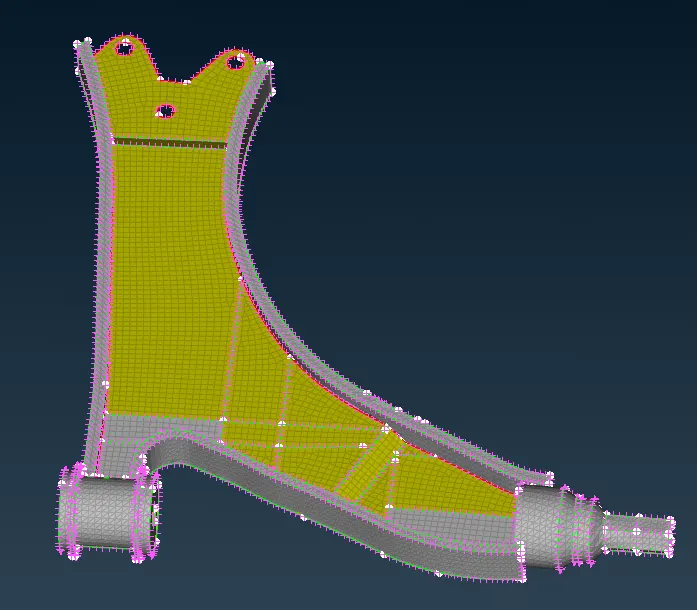
Volume meshing
Part 9:-
PID
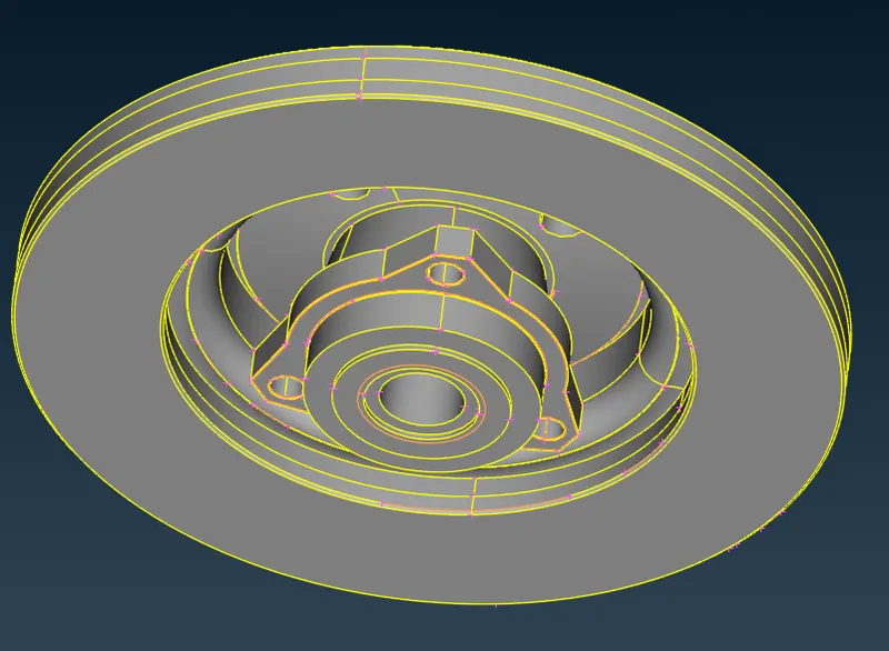
2D mesh
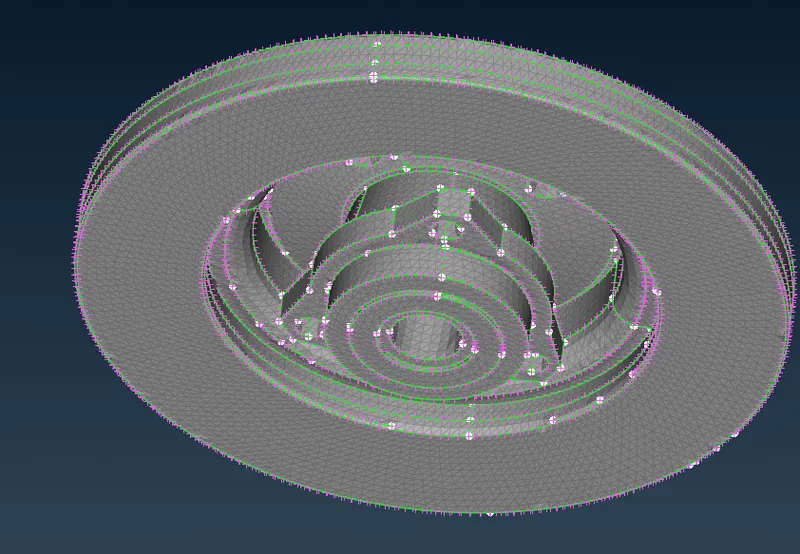
volume mesh
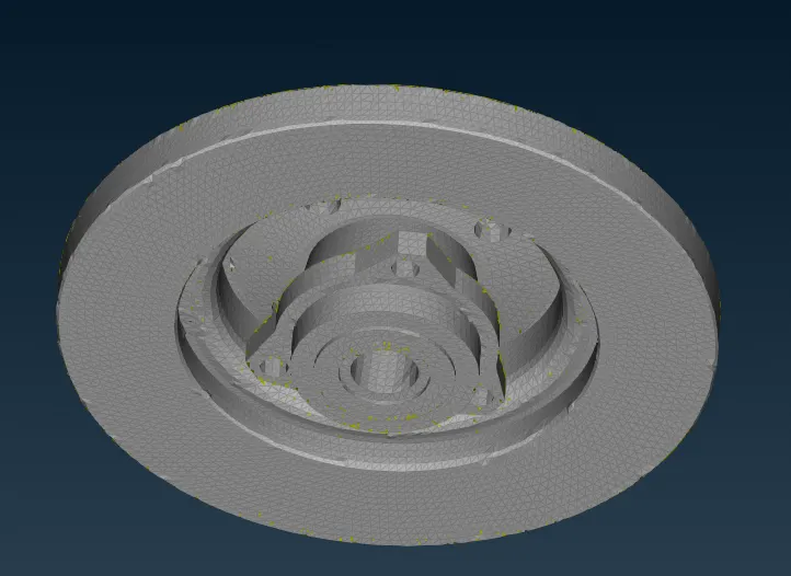
Part 10:-
PID
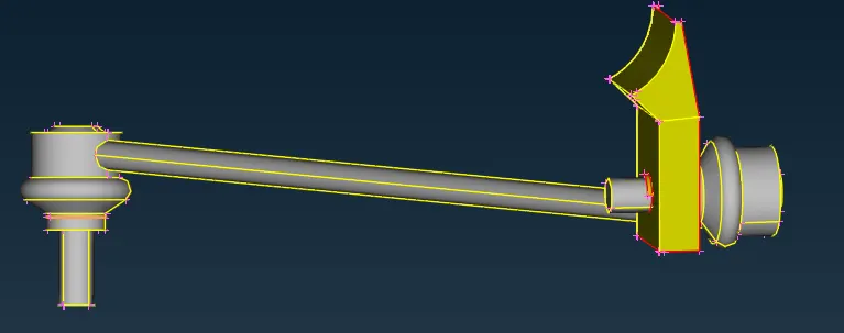
2D meshing
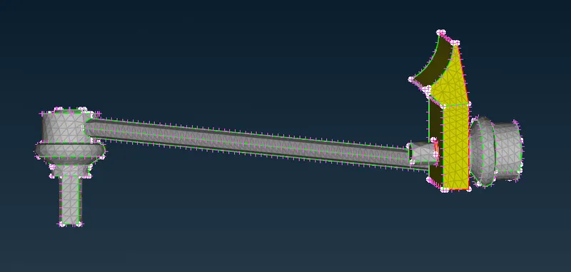
volume mesh
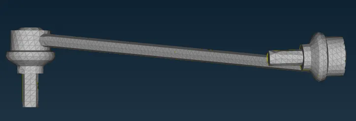
Part 11
PID
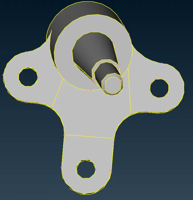
2D mesh
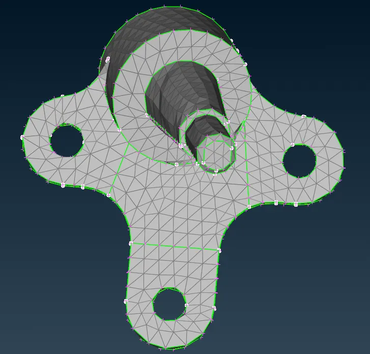
volume mesh
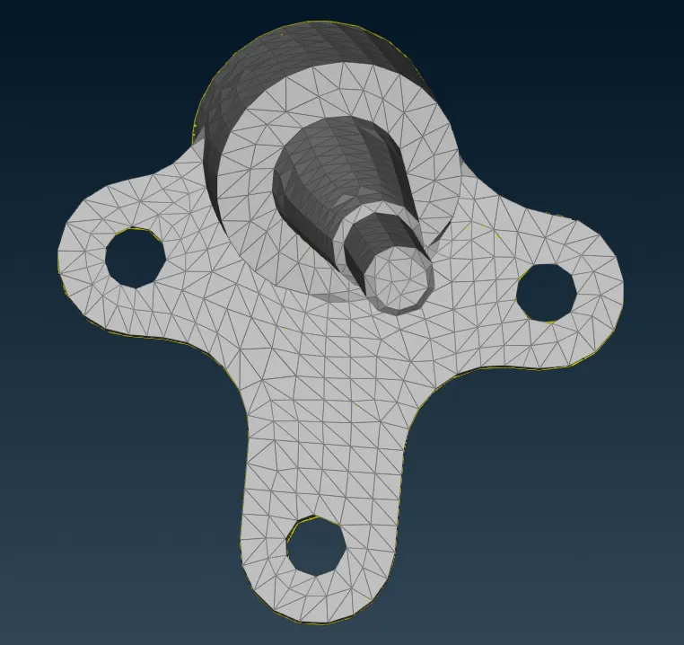
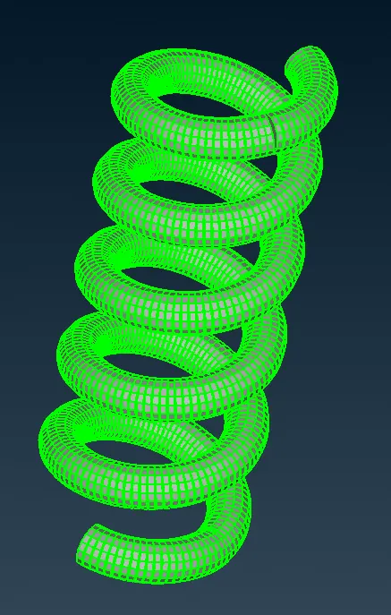
Spring concept
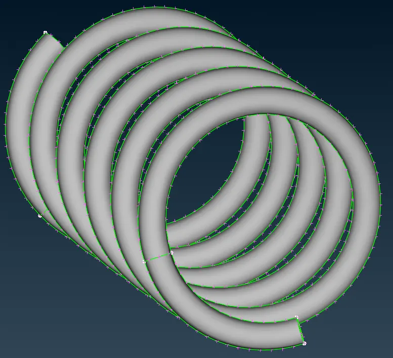
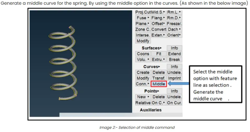
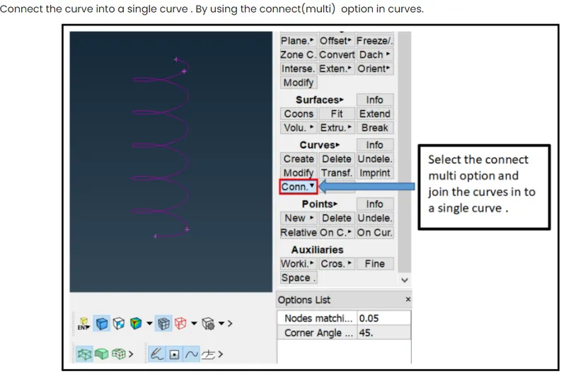
Select middle & create curve entire cross section of the curve & connect the curve into single by using connect multi in curves session
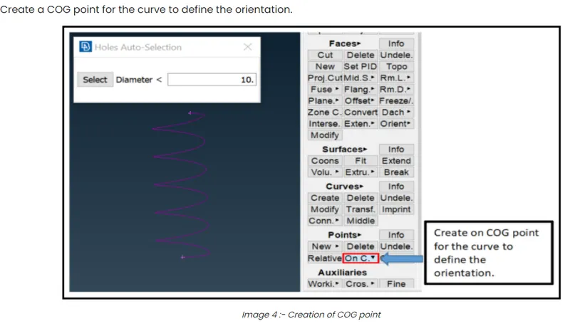
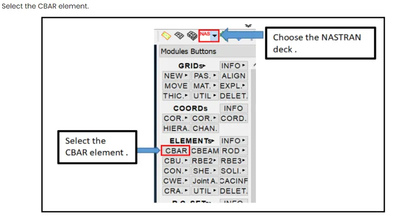
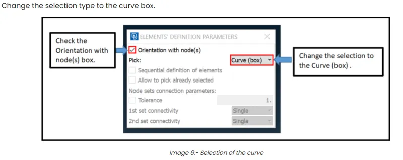
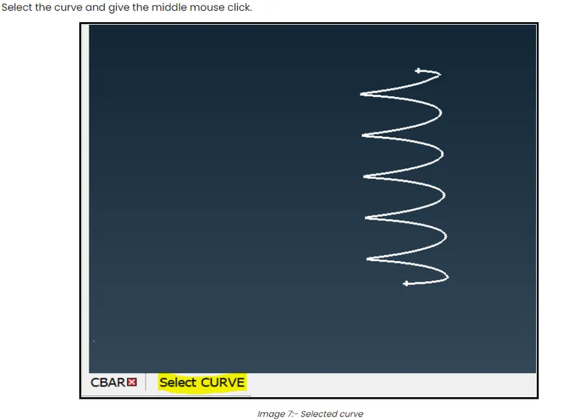
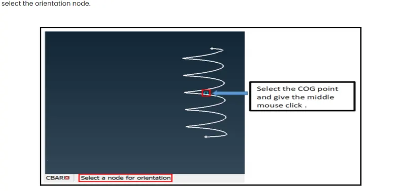
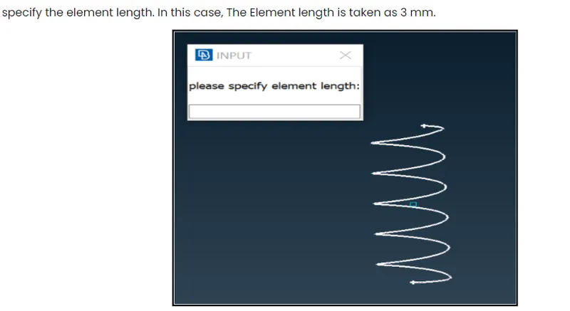

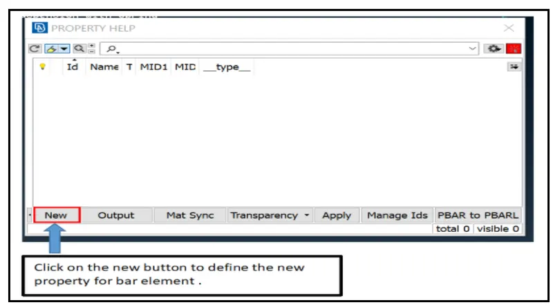
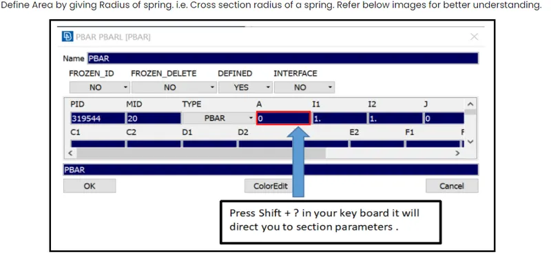
Specify the radius =10
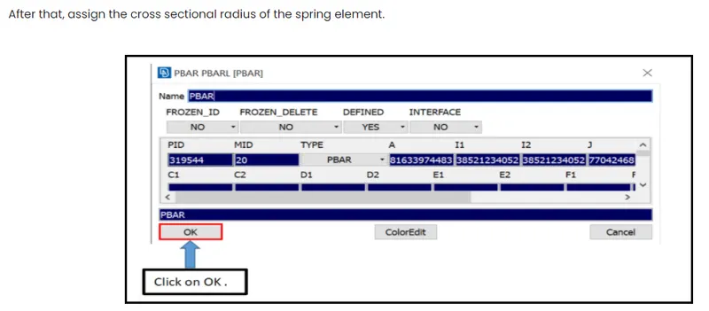
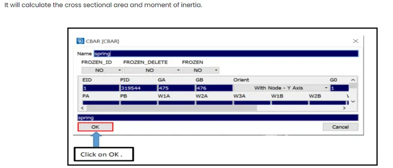
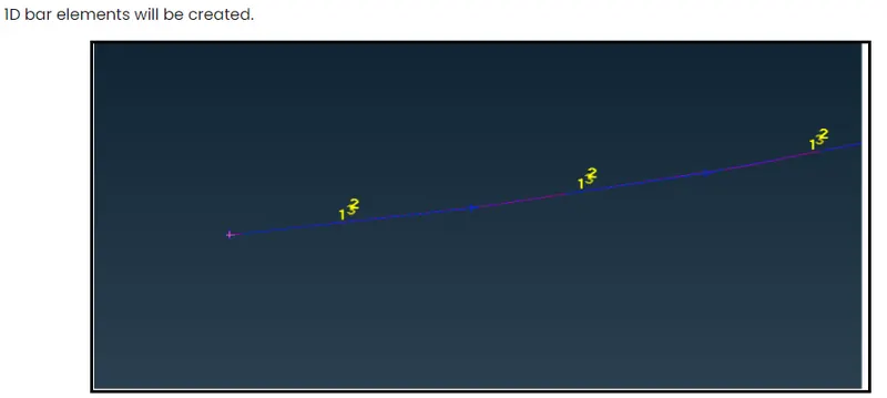
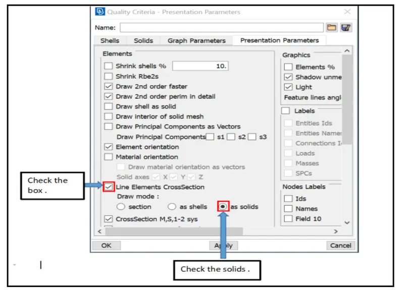

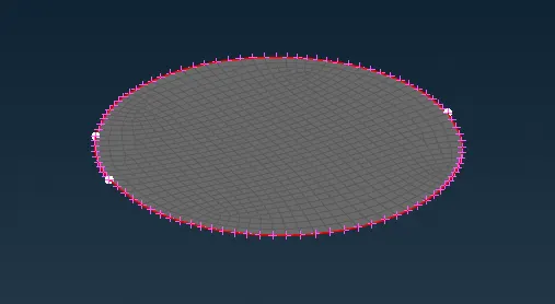
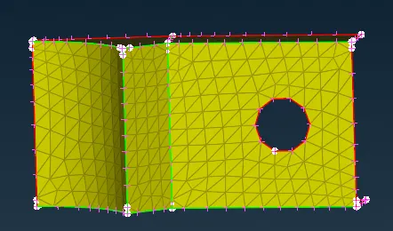
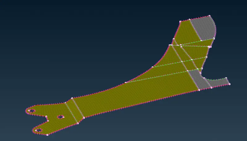
mid surface extracted for 3 components which are shown in below captures
Finally all meshing half portion with volume shown in below image
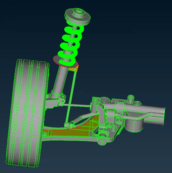
By using transforme
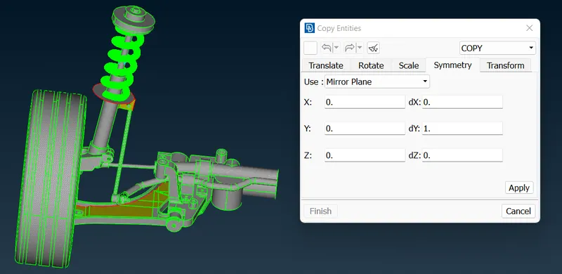
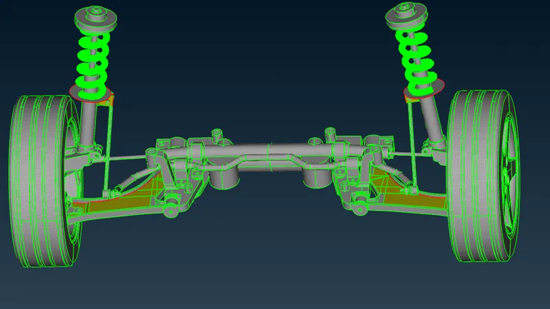
Conclusion:-
Hence conclude that the given model is modelled as per the above-mentioned quality criteria by utilising mid-surface meshing & volume meshing.
--
Thanks & regards,
Praveen Kumar Reddy.