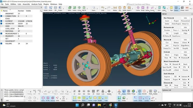
Project - 2 - Meshing on the suspension Assembly
MESHING AND DEPLOYING CONNECTIONS FOR A SUSPENSION ASSEMBLY USING ANSA PREPROCESSOR
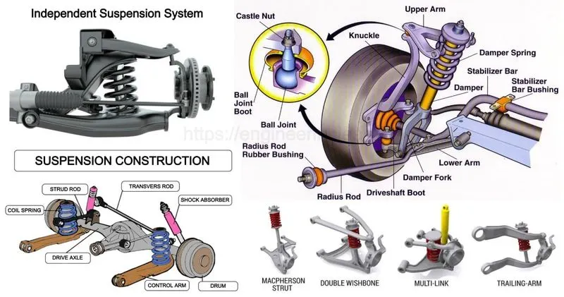
The chassis of vehicle is connected to the front and rear wheels through the medium of springs, shock absorbers and axles. All parts perform the function of protecting parts from shocks are known as suspension system.
The automobile chassis is indirectly connected with axles by springs. It is done to prevent the vehicle body from road shocks due to bounce, pitch, roll or sway. These road shocks provide an uncomfortable ride and also additional stress to the automobile frame and body.Suspension system has a spring and damper. The energy of road shock produced by the spring oscillates. These oscillations are arrested by the damper known as shock absorber.
AIM:
For the given suspension assembly component check for the geometrical errors and mesh (shell or solid meshing) with the given element Quality criteria. Assign proper thickness to the mid surface and deploy proper connections between various components in the suspension assembly.
PROCEDURE:
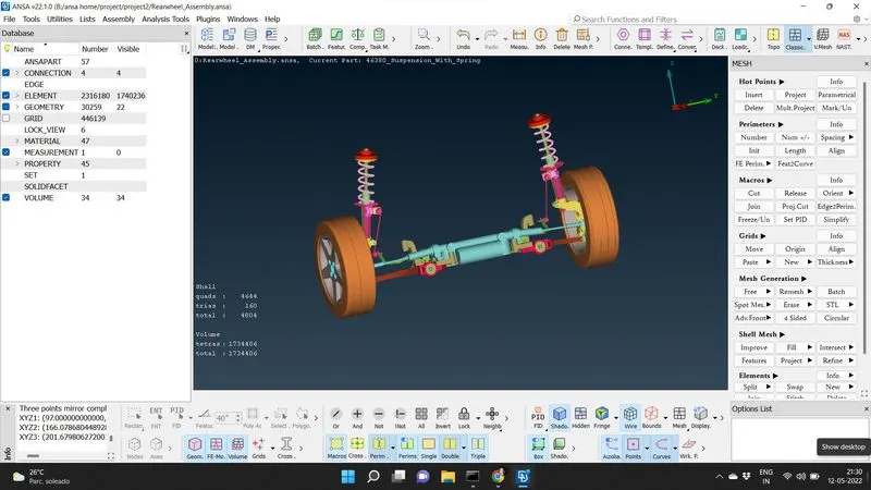
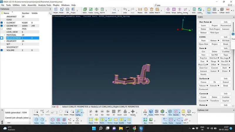
The ansa file of the suspension assembly is given and due to the part symmetry half of this is taken for meshing and deploying connection. we isolate each component of the system with seperate property identities.
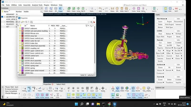
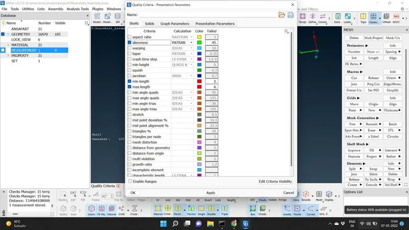
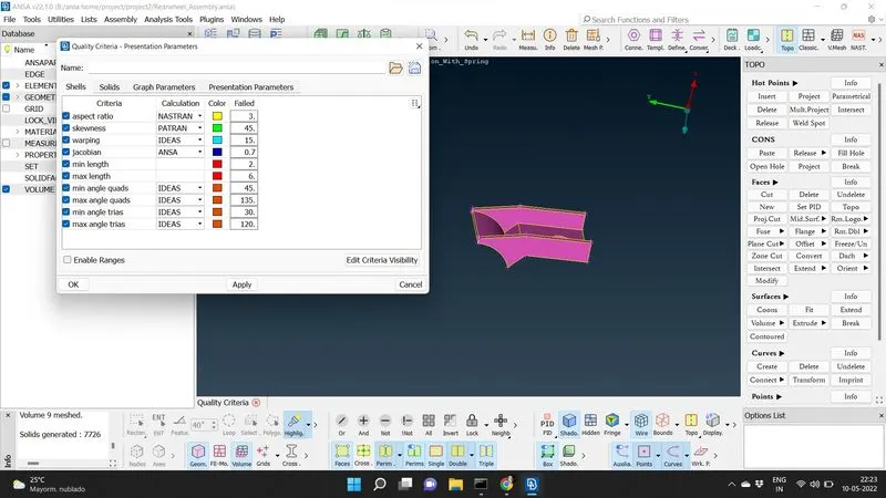
The geometry is checked for each components and appropriate quality and mesh parameters are given to each component.
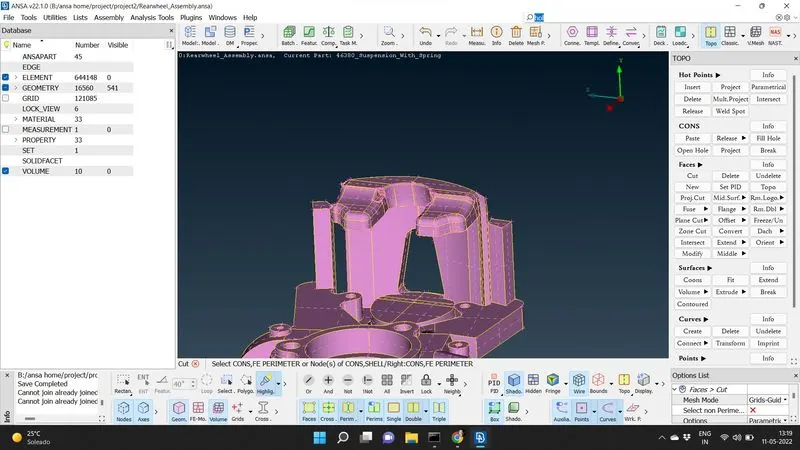
SOLID MESHING OF THOSE COMPONENTS WITH THICKNESS MORE THAN 5 mm:
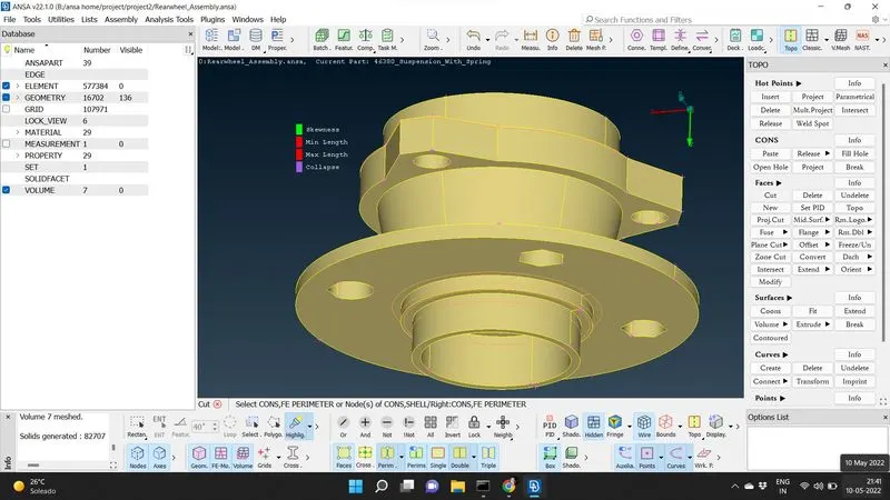
After clearing geometry of each solid componets for minimum length failure in the TOPO deck we proceed to mesh deck.Those components with thickness greater than 5 mm is taken for solid meshing, while others are treated as 2D meshing components. The spring is treated as a C-BAR element in Nastran deck while deploying connections as it is having uniform crossection throughout .We do spot meshing to generate tria mesh, we clear the off elements by reconstruction and smoothing the tria mesh generated ,satisfying the quality and mesh parameters. The average tria mesh length for Tyre and Rim is taken as 6.5mm, with minimum and maximum length of mesh as 5 and 10mm, while the average tria mesh length for other solids are 4mm, with minimum and maximum length of mesh as 2 and 6 mm. The skewness is taken as 45 for the tria mesh.
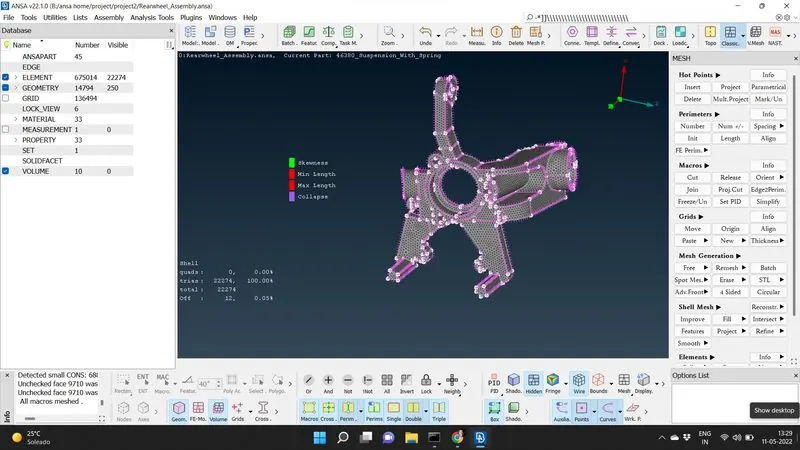
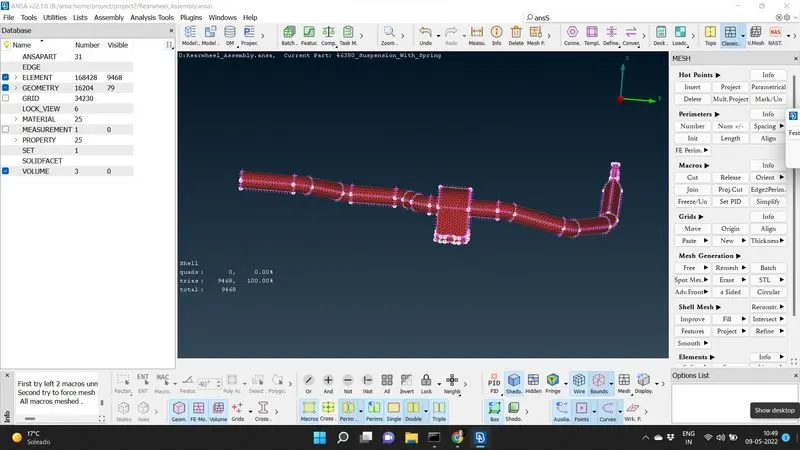
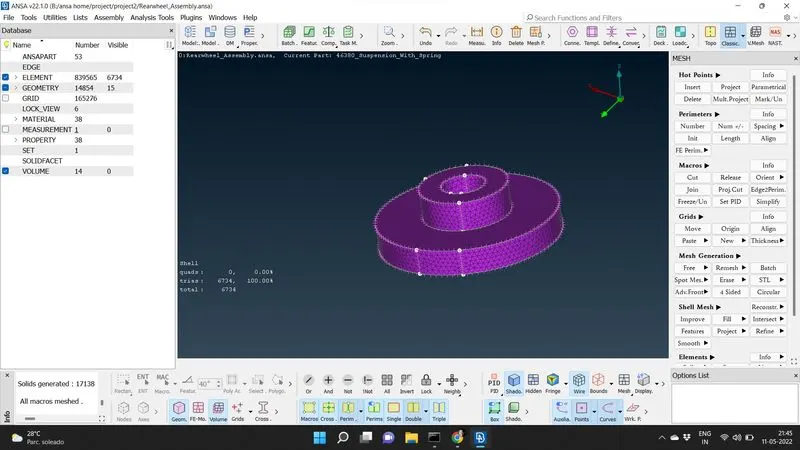
The tria mesh is converted in to tetra mesh elements in the volume mesh deck. We define the volume manually by selecting define- manual in the volume module in the volume mesh deck.The entire tria mesh part is selected using box selection. The volume defined is visible in the list of the volume moidule and we select remesh, so the ansa perform remesh automatically in tetra rapid to obtain the volume mesh. Though there are 2 tera mesh available in ansa ie. is Tetra rapid and Tetra FEM. anso generally perform Tetra Rapid with remesh. The tet- collapse of 0.2 is the only criteria for tetra meshing.
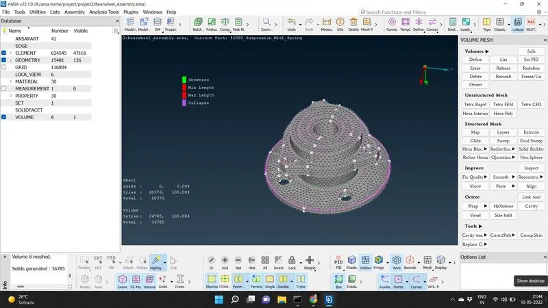
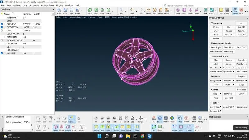
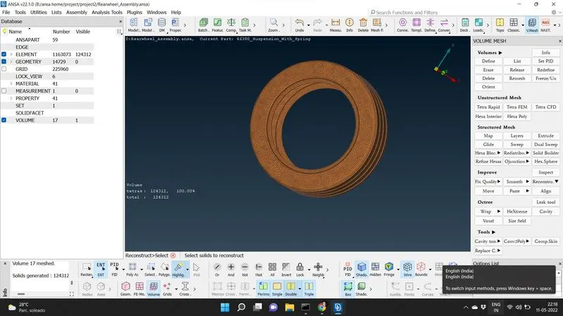
SHELL MESHING OF THOSE COMPONENTS WITH THICKNESS LESS THAN 5mm:
After clearing the geometry for minimum length failure by supressing some feature lines in the Topo deck, we extract the midsurface using faces middle in the topo deck. The meshing of the mid surface is done in the mesh deck using spot meshing in the mesh generation module satisfying mesh and quality parameters. The shell mesh generated is reconstructed to remove off elements.
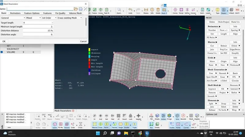
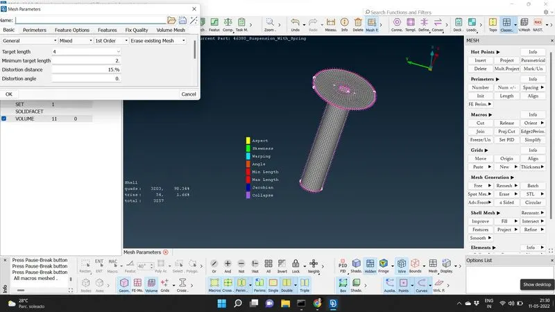
REPRESENTING SPRING AS A 1-D ELEMENT AND DEPLOYING CONNECTIONS AS A CBAR ELEMENT:
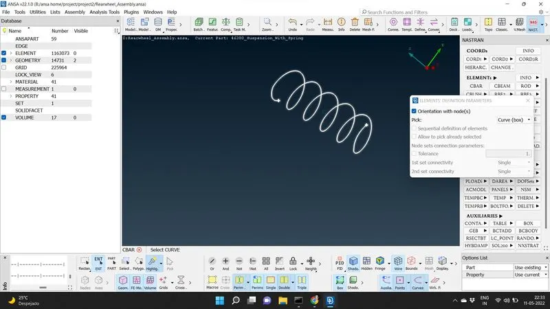
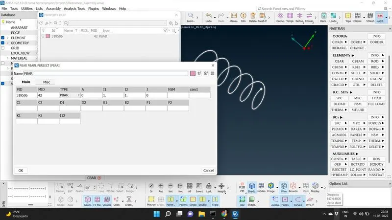
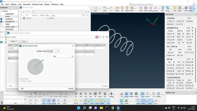
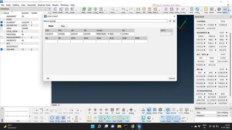
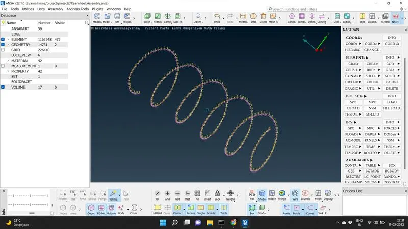
As the spring is having uniform thickness over its cross section, we can use curve middle from TOPO deck to generate a curve in the middle. The curves generated are connected to form a single curve using curves, connect, multi. We generate a COG. point selecting curve and points, on COG. We select CBAR, Elements from Nastran deck. we select the curve and give orientation by selcting the COG. point created earlier. we can input the radius of the curve as 5mm and the length as 3mm. The 1-D element of the spring created can be viewed as a solid component by selecting draw mode as solid of line elements cross section in the quality parameters.
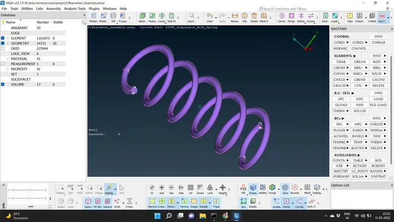
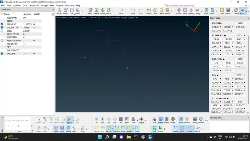
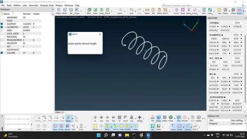
DEPLOYING CONNECTIONS:
1) RBE2 CONNECTIONS
2) SEAM WELD
3) MANY NODE CLUSTER RBE2 CONNECTIONS
RBE2 CONNECTIONS:
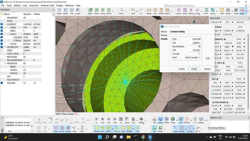
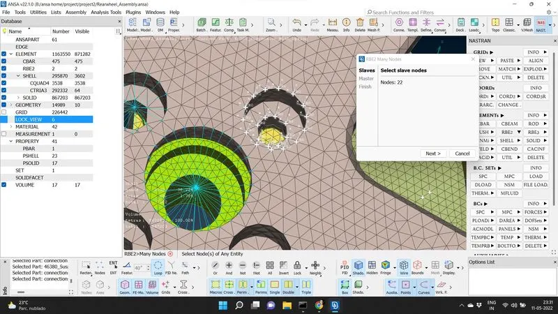
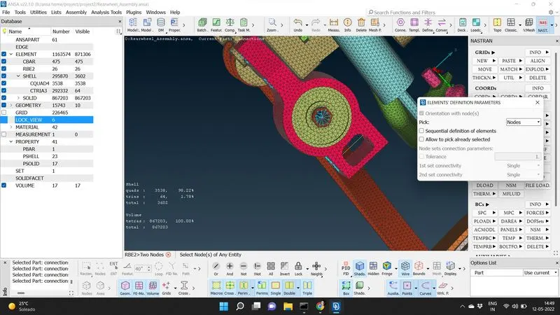
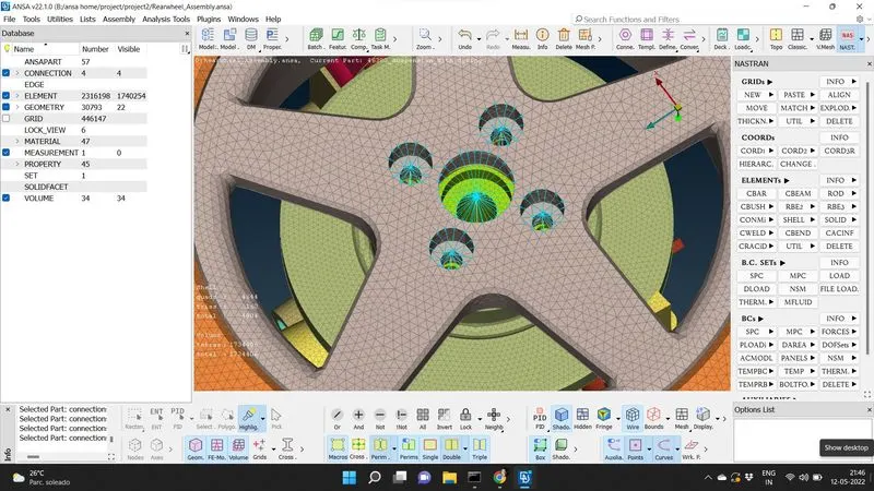
We can denote the connections between some parts as rigid body elements, where in the elements movement can be restricted in 6 directions (3 translational and 3 rotational). To reperesent this connection, we need to select many nodes of RBE2, elemnets module from Nastran deck. We select the circumference of the mating hole using loop or feature at 40 degree selection to select slave nodes. Master node is created at center of gravity point by ansa. The degree of freedom is given as 123456 ( restricting movement of node in all 6 directions). In the case of a bolt connection inside a hole, a stem is created in between two master noide by selecting 2 node, RBE2 in the elements module from Nastran deck. The stem is identitified as a connection in yellow line connecting 2 master node in a RBE2 connection.
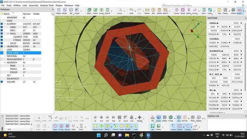
It can also be represented as a bolt connections alternatively by creating a COG. point of the holes using ON COG. of points module in TOPO deck. The COG. point is converted in to bolt connection by selecting bolt of the 3 d points using convert in the assembly tab. The bolt connection is realized using the connection manager and selecting the bolts created. Select the 2 parts where the bolt connection is present and FE. representation type as bolt after giving the search distance as 10. The bolt connection is then applied and realized.
SEAM WELD:
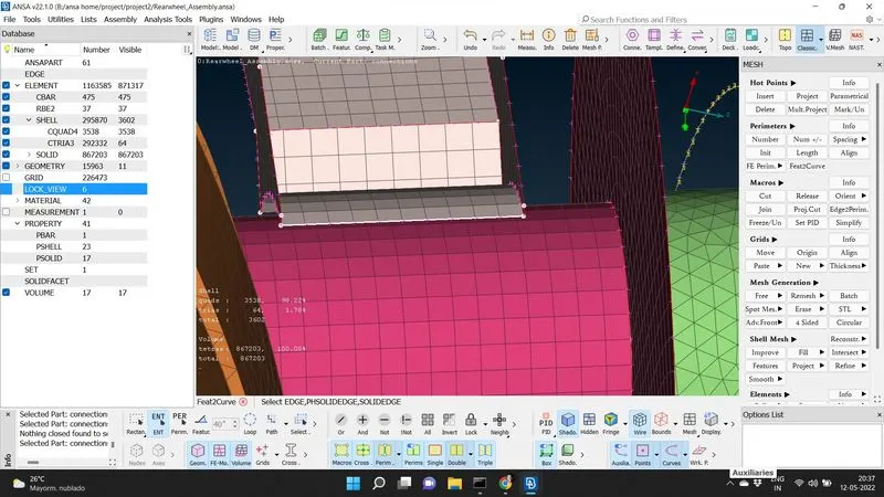
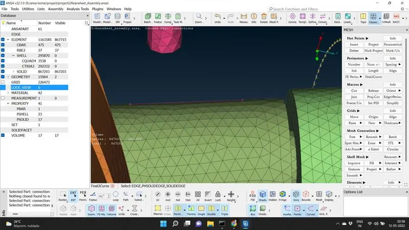
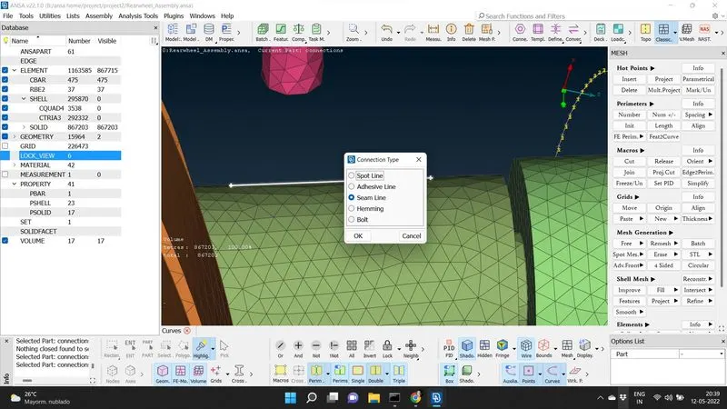
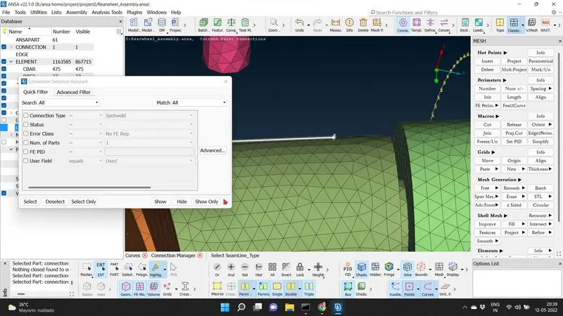
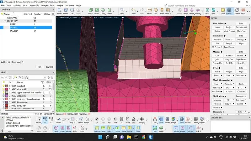
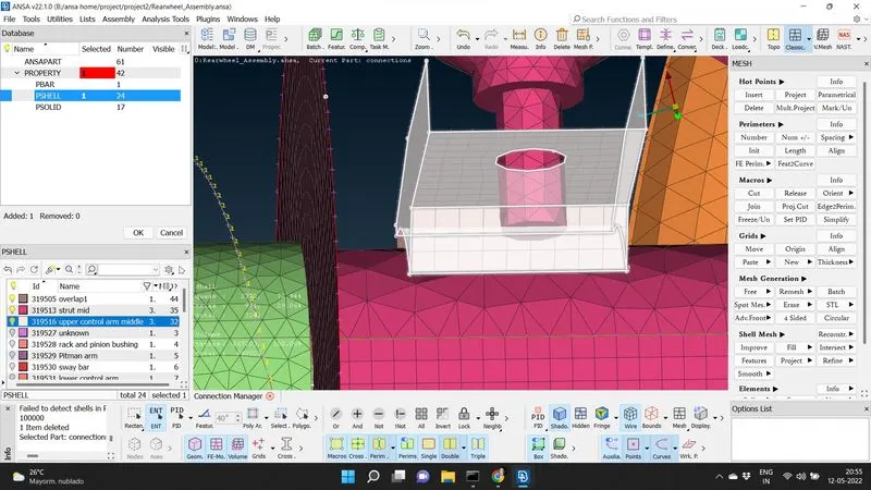
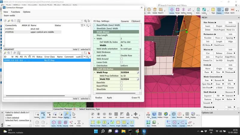
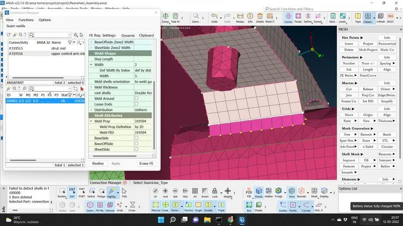
For seam weld we need to generate a curve on the shell elements, we select feature 2 curve on perimeter module of mesh deck. The curve created is converted to seam line using convert in the assembly tab. The seam weld is realized using connections manager and selecting the seam line created. Select the 2 parts where seam weld should be done and FE. representation type as overlap shell. we should give the search distance as 10 mm and width of the weld as 3mm, root shell as double row and define weld identity as new shell property identity and then apply and realize the connection.
MANY NODE CLUSTER RBE2:
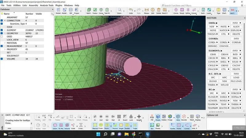
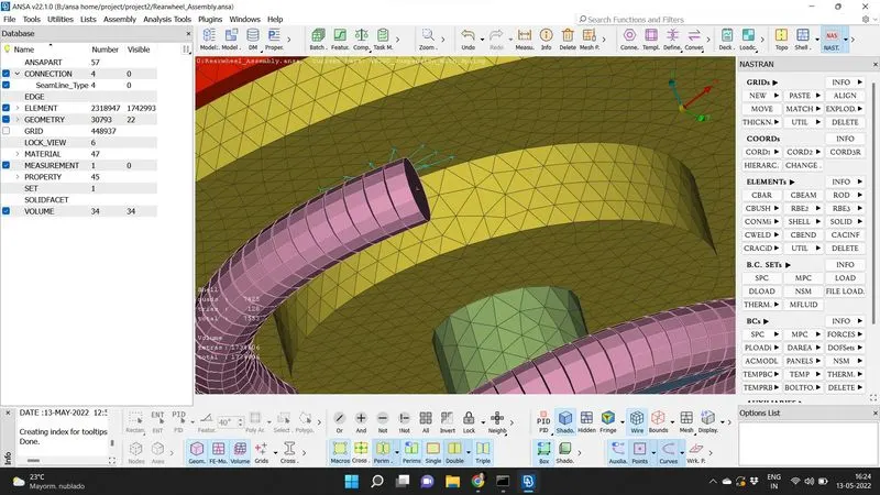
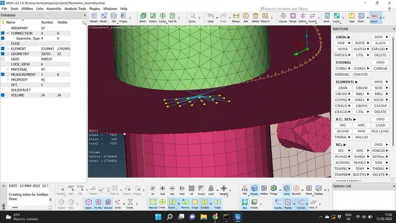
The major difference with this connection and the bolt or RBE2 connection is that there is no stem connecting 2 master nodes and is a rigid connection without nut or bolt. We use this connection for representing the rigid connection between the spring element and the 2D shell component. We should select the nodes many nodes from RBE2 , elements module of Nastran deck. we should select the nodes using nodal entity as selection and on confirming the selection a RBE2 cluster with a common master node is formed.
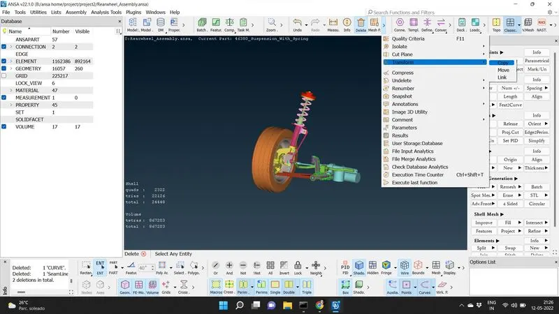
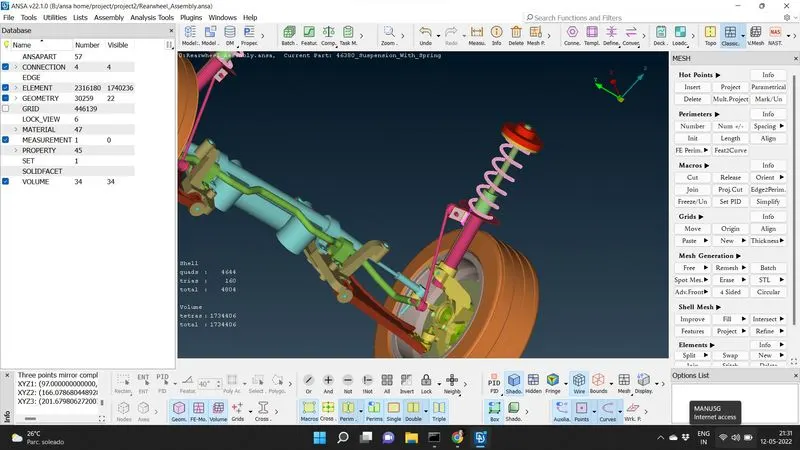
After giving appropriate connection we do the symmetry operation to obtain the complete suspension assembly. For this we select entities- copy, transform in the uitility tab. We select the meshed model using box selection and on confirming we select mirror 3 point plane in the symmetry tab. we select 3 random points having different coordinates and select apply to get the complete meshed model with suitable connection.
LEARNING OUTCOMES:
Through this project i was able to identify the difference between shell meshing and solid meshing while gathering an insight on converting tria mesh elements in to tera mesh elements. To clear the off elements in volume meshing was also performed. A practise on spring element meshing and connection by treating it as a CBAR elements and the difference between RBE2 and many nodes RBE2 cluster is also understood. After meshing, through symmetry we were able to reflect the meshed surface with necessary connections to have a complete suspension assembly.
CONCLUSION:
A meshed suspension assembly with suitable connections is obtained satisfying the given quality and mesh parameters are obtained.