Project - 2 - Meshing on the suspension Assembly
Objective:-
- For the given assembly,check for the geometrical errors and mesh with the given element Quality criteria.
- After meshing the component the thickness has to be assigned for mid surface .
- Use tetra element to model non uniform thickness components.
- Deploy connection between components.
Quality criteria :-
- In this model, we have been provided with three different criteria for different parts.
Quality Criteria for Surface Meshing of Tyre and Rim (Element type: Tria) :
|
S.No |
Quality Criteria |
Value |
|
1 |
Target/Average length |
6.5 |
|
2 |
Minimum Length |
5 |
|
3 |
Maximum Length |
10 |
|
4 |
Skewness |
45 |
Quality criteria for Surface Meshing of Non-Uniform thickness components other than Tyre and Rim (Element type: Tria) :
|
S.No |
Quality Criteria |
Value |
|
1 |
Target/Average length |
4 |
|
2 |
Minimum Length |
2 |
|
3 |
Maximum Length |
6 |
|
4 |
Skewness |
45 |
Quality Criteria for Volume meshing of all Non-Uniform thickness components (Element type: Tetra Elements):
|
S.No |
Quality Criteria |
Value |
|
1 |
Tet-collapse |
0.2 |
Quality criteria for Mid surfacing of Uniform thickness part which has a thickness less than 5 mm (Element type: Mixed elements) :
|
S.No |
Quality Criteria |
Value |
|
1 |
Target/Average length |
4 |
|
2 |
Minimum Length |
2 |
|
3 |
Maximum Length |
6 |
|
4 |
Aspect |
3 |
|
5 |
Warpage |
15 |
|
6 |
Skewness |
45 |
|
7 |
Jacobian |
0.7 |
|
8 |
Minimum Quad Angle |
45 |
|
9 |
Maximum Quad Angle |
135 |
|
10 |
Minimum Tria Angle |
30 |
|
11 |
Maximum Tria Angle |
120 |
Quality Criteria for Surface Meshing of Tyre and Rim (Element type: Tria) :
|
S.No |
Quality Criteria |
Value |
|
1 |
Target/Average length |
6.5 |
|
2 |
Minimum Length |
5 |
|
3 |
Maximum Length |
10 |
|
4 |
Skewness |
45 |
Quality criteria for Surface Meshing of Non-Uniform thickness components other than Tyre and Rim (Element type: Tria) :
|
S.No |
Quality Criteria |
Value |
|
1 |
Target/Average length |
4 |
|
2 |
Minimum Length |
2 |
|
3 |
Maximum Length |
6 |
|
4 |
Skewness |
45 |
Quality Criteria for Volume meshing of all Non Uniform thickness components (Element type: Tetra Elements):
|
S.No |
Quality Criteria |
Value |
|
1 |
Tet-collapse |
0.2 |
Quality criteria for Mid surfacing of Uniform thickness part which has a thickness less than 5 mm (Element type: Mixed elements) :
|
S.No |
Quality Criteria |
Value |
|
1 |
Target/Average length |
4 |
|
2 |
Minimum Length |
2 |
|
3 |
Maximum Length |
6 |
|
4 |
Aspect |
3 |
|
5 |
Warpage |
15 |
|
6 |
Skewness |
45 |
|
7 |
Jacobian |
0.7 |
|
8 |
Minimum Quad Angle |
45 |
|
9 |
Maximum Quad Angle |
135 |
|
10 |
Minimum Tria Angle |
30 |
|
11 |
Maximum Tria Angle |
120 |
Geometry cleanup:-
- import the model into ANSA page as show below figure.
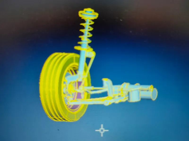
- As we done with the first step i,e we import cad model into ANSA pase as shown in the above figures.
After that we check for the geometry as shown below figure. 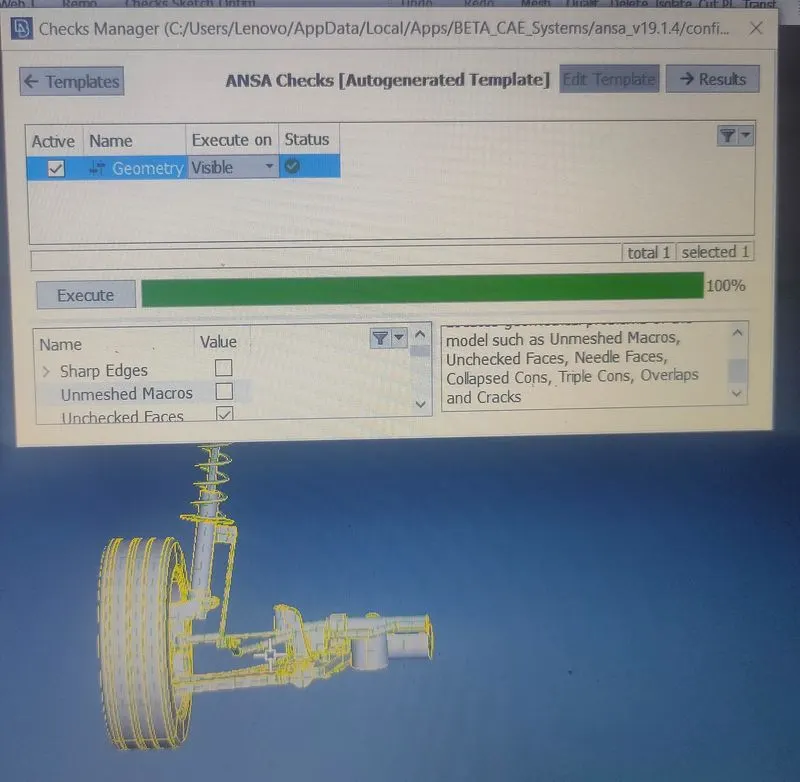
Meshing Tyre and Rim:-
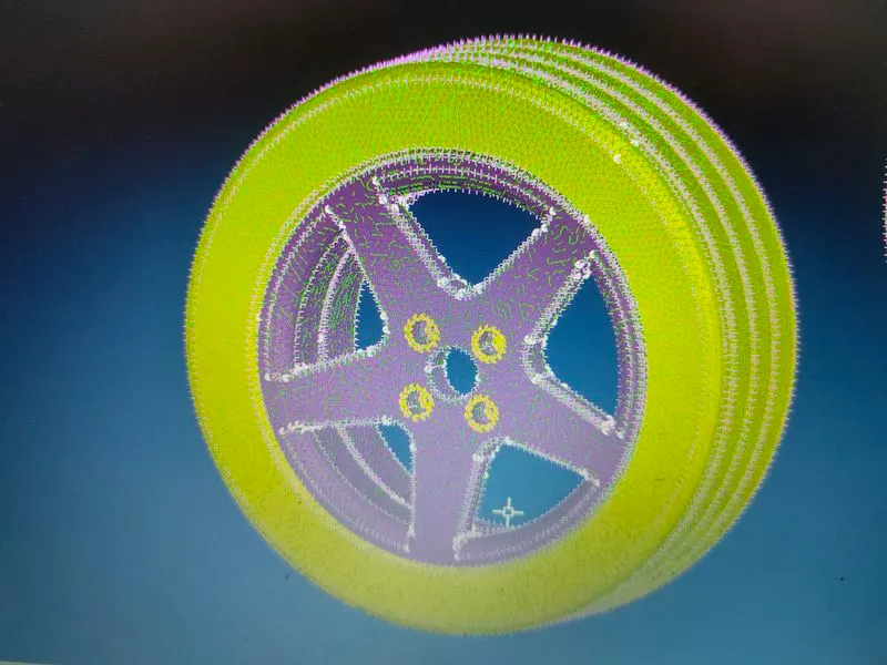
- Since the tyre and the rim have different quality criteria we meshed it separately.
In order to create the tetra, we first have to do 2D mesh.
In order to do that we fed the given criteria to the ANSA.
In order to mesh these parts, we used mesh Generation>Spot mesh, below image shows the same. - For meshing the plane surface we used tria elements how ever, for curved features we used Ortho tria.
The off element were corrected using Reconstruction.
Rim and Tyre meshed using Shell mesh:-
Features with varying thickness:-
- For such regions we have been provided with separate quality criteria,thus we have to re-enter quality and mesh parameters.The same has been shown above.
For these features we will use similar technique as used for rim and tyre.The below image shows these features with shell mesh. 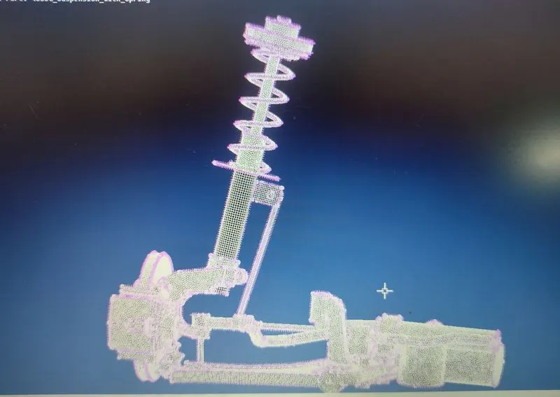
Now in order to create 3D mesh we have to first define the volumes.in order to do so we have to go Volume Mesh Deck>Volumes>Define>Manual.
However,for few feature we need to divide it into few parts and define each part separately,otherwise it may give errors while generating volume mesh.
All the defined volumes in given model are shown below.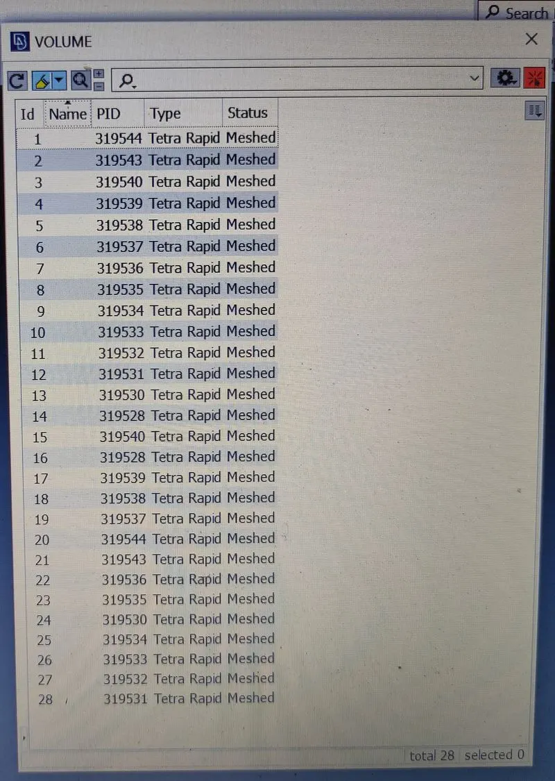
Once volume is defined we can generate volume mesh either using TETRA FEM orTETRA RAPID.
Tetra FEM is generally used for structural analysis and it is important to define the volume for this ,however,Tetra Rapid mesh is used for automatic generate of Tetrahedral mesh and defining volume separately is not required.
Features with uniform thickness:-- As per the requirement of the project we have to generate mid surface for the features with uniform thickness of 3mm.
In order to create a mesh for these features, we used Face>offset.
The below image shows mid surface generation using this method. 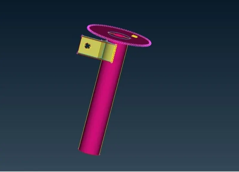
we above-given Quality criteria to ANSA and generated mesh using mesh Generation>spot mesh.
For this we used Mixed elements. off elements received were fixed using reconstruction tool.
below image shows the mesh created.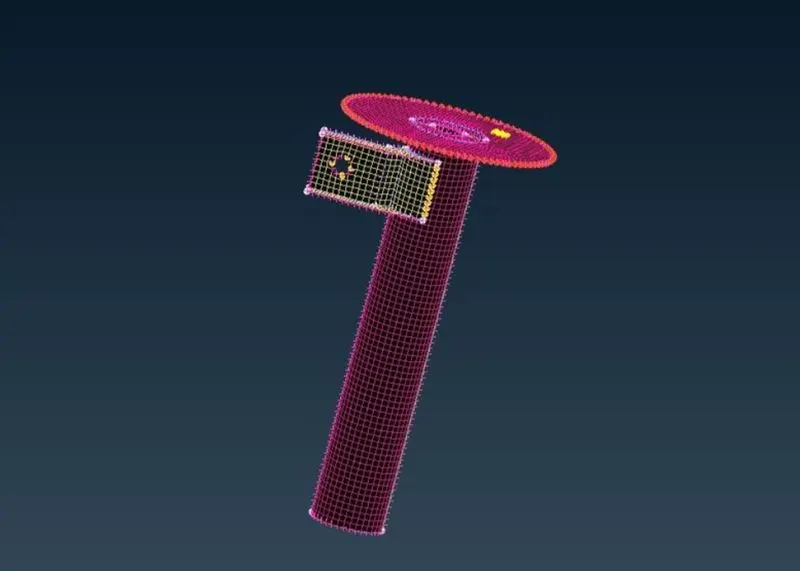
Representing Spring as 1D Bar Element:-- In order to show the spring as 1D element ,we have to first create a curve,which was done using Curves>Middle.
We will join the all curves connect element convert using connect>Multi.
Once done we will create a COG Point on curve.
Once create we need to open NASTRAN Deck>Element>CBar>Curve Box.
After selecting the curve we have to enter the element size radius of the element.procedure to do so generate is show below. 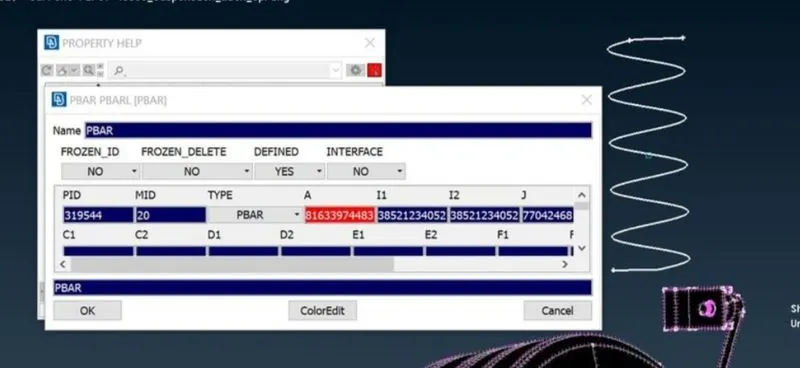
Once the 1D element is created to view the repersentation as solid we have to change line Element Cross section as solid in Presentation parameters.
below image shows Spring as the 1D Bar element.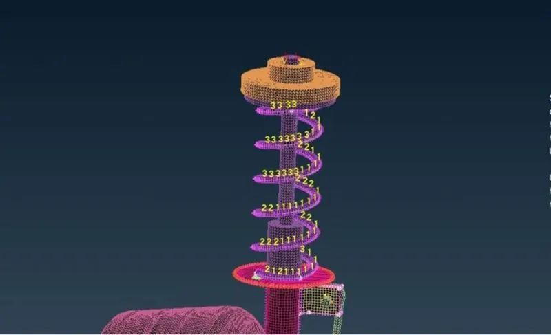
connections:-- We have applied Seam weld on strut bracker.
In order to create seam weld,we first used CONS2Curve Tool.
Then using convert we converted it into seam line.
Now using Connection Manager,we realised the connection for FE REP we used OVER LAP SHEEL.below image shows the seam weld connection after realising. 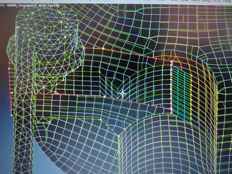
Bolts:-- For representing Bolts connection we have used RB2 Cluster on each side and connected them using RB2 Two node.
As shown below figures. 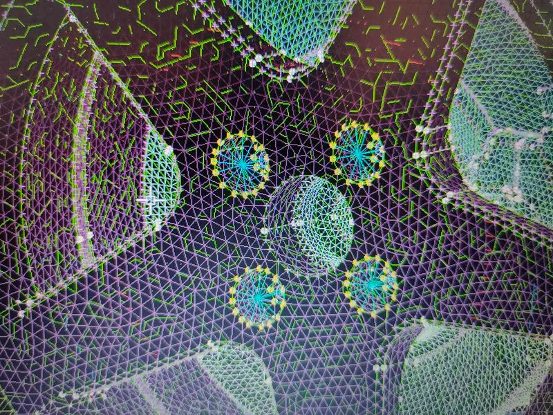
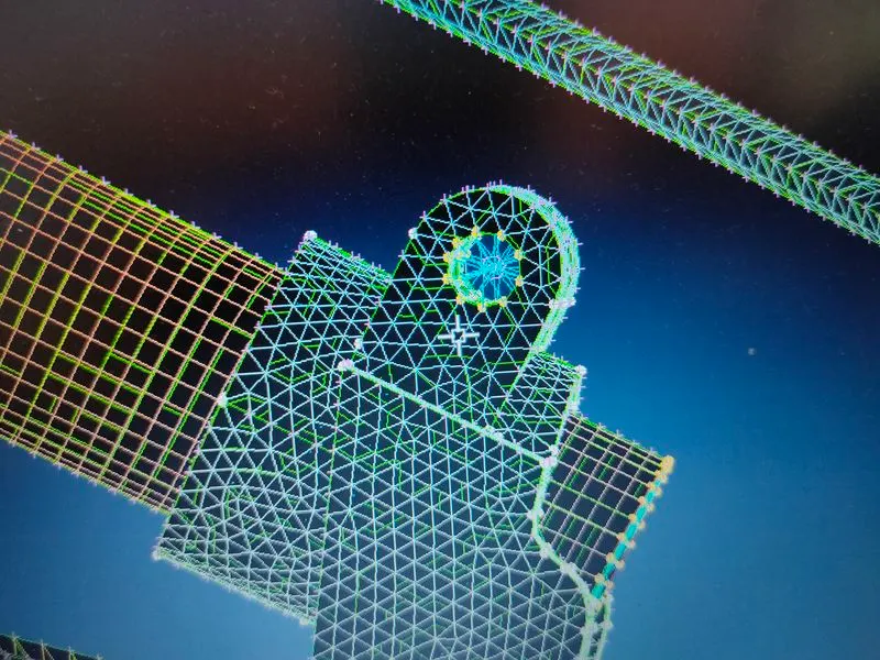
Also, for features having their spilnes or joints connected with hub of other component we represented them as locked using many node RB2.
Also as spring connection show as below figures.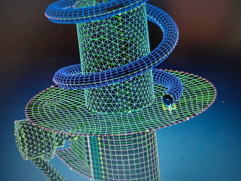
Once all required connections are made our model is ready ,below is image of complete FE model of the assembly.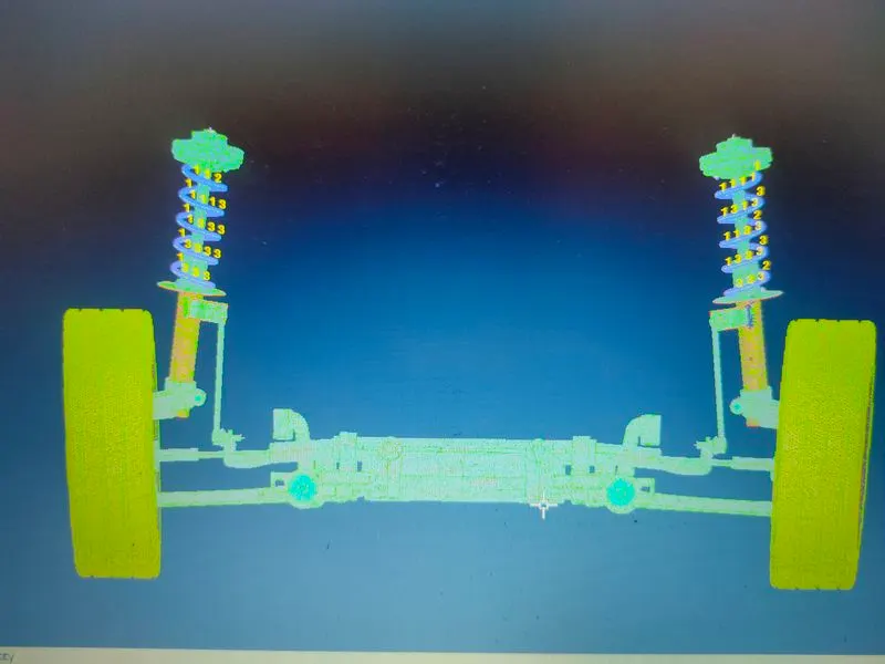
Conclusion:-- The model has been completed as per requirement.
The mesh for different component has been generated with given quality criteria.
Mid surface is generated for features with uniform thickness and meshed with shell element,Volume mesh has been done on other components.
All required connections have been made.