Project 2-Highway Assistant-Lane Changing Assistant
Procedure and Steps:
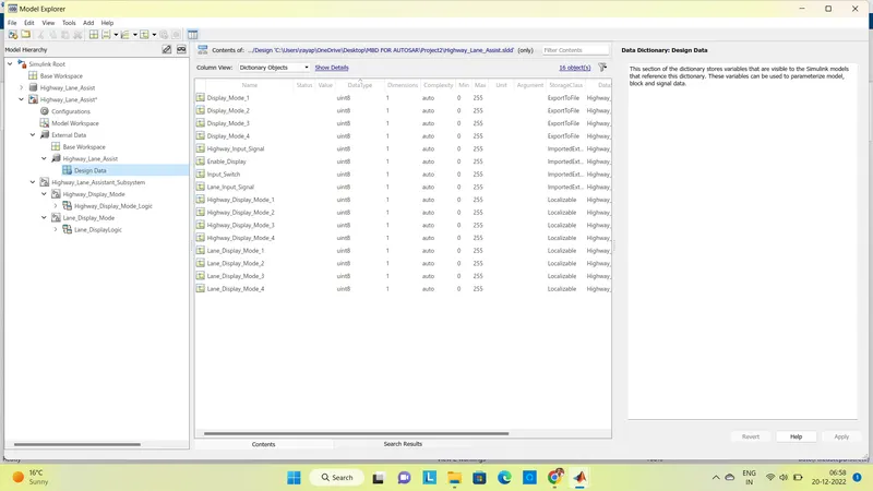
The first step is the creation of the Simulink Data Dictionary File from the given calibration and signal data list. Then data dictionary should be linked to the specified simulink model.
As per the first requirement, the first subsystem will have three inputs. They are Highway_Input_Signal, Enable_Display, and Input_Switch.
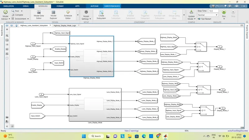
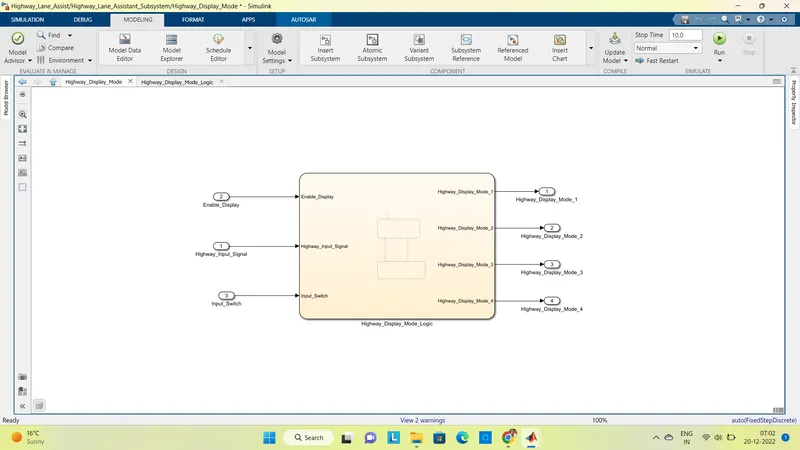
The input further goes to the chart. The chart will have the output as Highway_Display_Mode_1, Highway_Display_Mode_2, Highway_Display_Mode_3, and Highway_Display_Mode_4.
inside the chart, we will implement Highway_Input_Signal, Enable_Display, and Input_Switch using AND blocks. The output is given in the State.
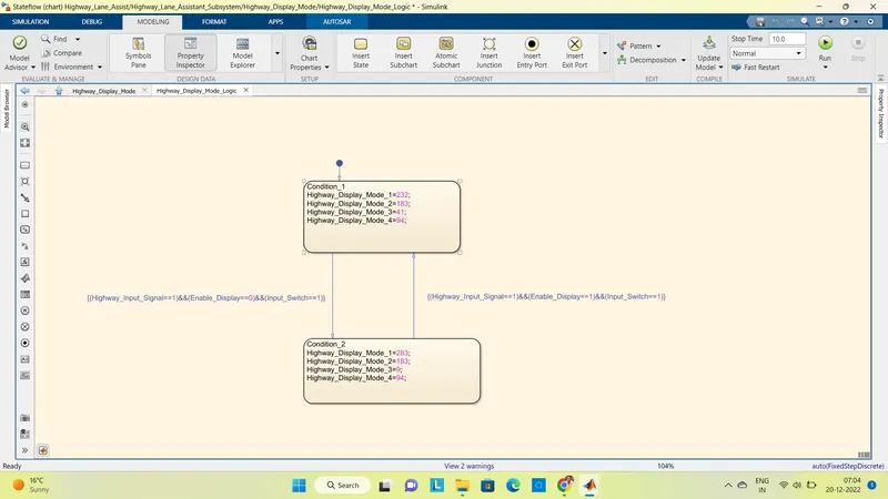
Once the Stateflow logic is written, we will resolve the port for input and output.
As per requirement 2, we will enable the subsystem using Lane_Input_Signal for a value of 6. Input for the block will be Input_Switch and Enable_display. Here, from and to blocks are used to make connections easy and readable.
EN_D= Enable_Display, IPS= Input_Switch, HIS= Highway_Input_Signal, HD1= Highway_Display_1,...., HD4= Highway_Display_4, LD1= Lane_Display_1,...., LD4= Lane_Display_4.
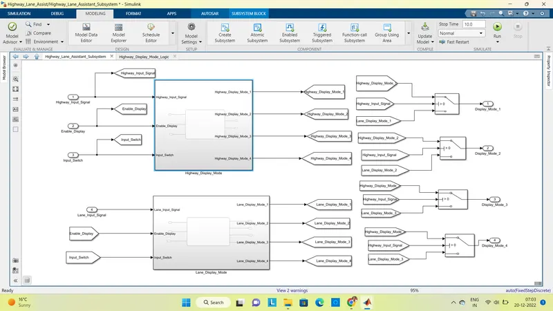
These inputs will further go to Chart, where the Stateflow logic will be written. The output of the chart are Lane_Display_Mode_1, Lane_Display_Mode_2, Lane_Display_Mode_3, Lane_Display_Model_4.
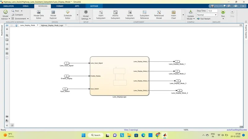
nside the chart, the Enable_Display and Input_Switch are used to make logic for Lane Display output.
The main output is written inside the State for Lane_Display_Mode
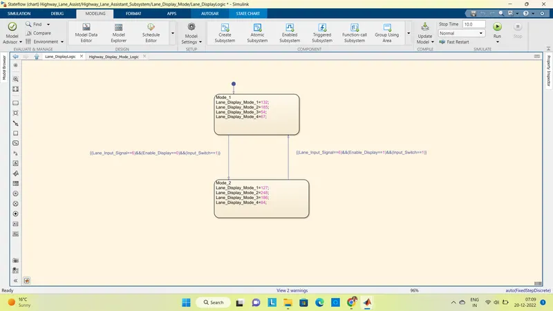
The input and output signals are then resolved.
The output of the Highway_Display_Mode and Lane_Display_Mode are provided to the Switch block. That is in total 4 switch blocks are used. The conditional input signal is taken as Highway_Input_Signal for all the blocks.
The final model from the inside can be seen like this:
To give a better look we will put all this in a single subsystem. For better visualization, we will mask the subsystem with the appropriate image.
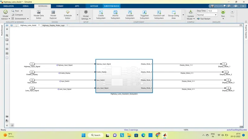
Then we will make the model in compliance with the AUTOSAR. So, all the input & output signals will be mapped into the Autosar Editor.
But prior to that, we will set the System target file as autosar.tlc
We will make sure that in Solver we will set the solver to Fixed-Step.
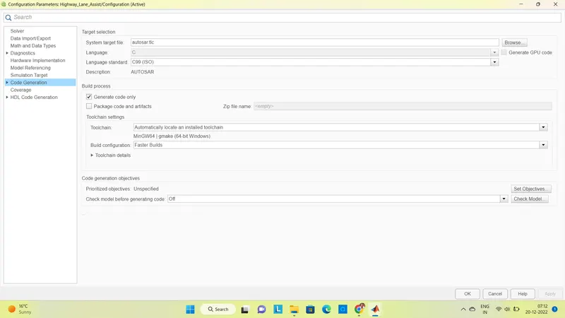
Then under App, we will select the AUTOSAR component.
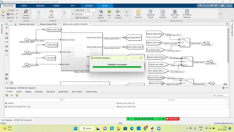
This will open Code Mapping - AUTOSAR SW Component.
For the Reciever port of the model, that is input, we will rename the port with the prefix Rp_.
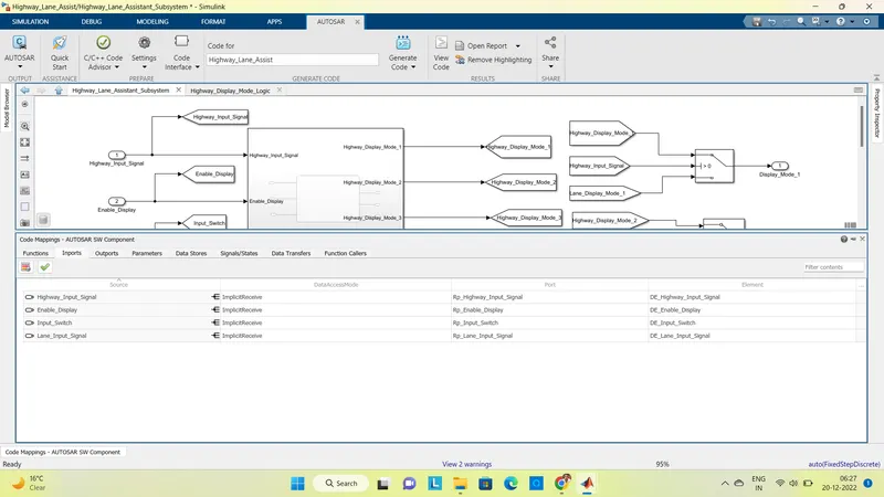
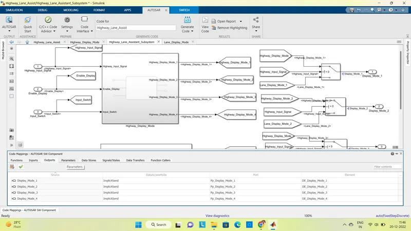
For the Sender port of the model, that is output, we will rename the port with the prefix Pp_.
For the S-R Interfaces of the model, we will rename the port with the prefix SRIf_.
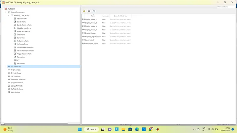
For the Data Elements of the model, we will rename the port with the prefix DE_.
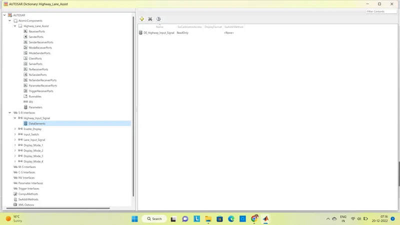
Then the model was validated with AUTOSAR Compliance.
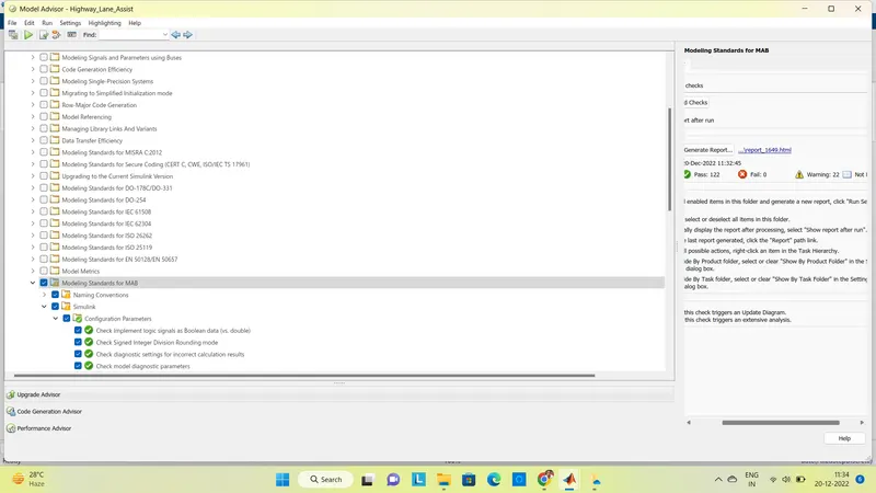
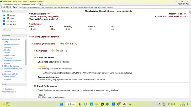
The following is the Model Advisor Report:
code generation:
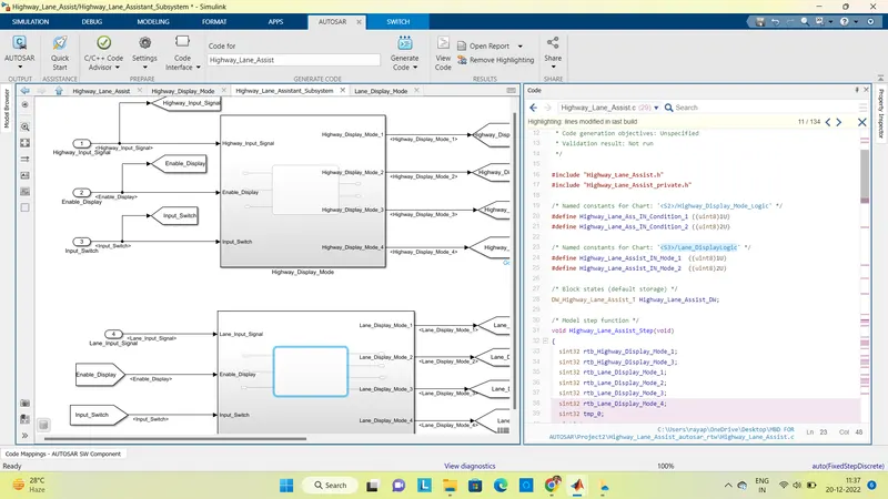
The generated report along with the SLDD, Model, Code generation and screenshots, all are given in the zip file.