Project 2-Highway Assistant-Lane Changing Assistant
Problem Articulation:
To foster one explicit necessity of Roadway Collaborator - Path Changing Colleague calculation. If it's not too much trouble, note that the entire Interstate Colleague - Path Changing Collaborator is an exceptionally immense calculation and just a single little piece of the rationale is carried out here. The thought is to acclimate with ideas of Autosar Programming Part Advancement in MATLAB Climate by observing the Model-Based Improvement rules. The Venture should be finished remembering the accompanying cycles and steps.
This model should be created in MATLAB Simulink per MBD rules. Code Age Profile should be Autosar Coder.
Simulink Information Word reference should be made for the model and should be connected to the model. All the info and result signals should be planned in the Autosar Manager.
Model Consultant Report is required and this will be trailed by Code Age.
Highway Associate - Path Changing Colleague introduction to the Element:
The Roadway Aide upholds the driver and assumes control over the longitudinal and horizontal direction of the vehicle in
repetitive driving circumstances on roadways. To some degree, mechanized capability can consequently begin, speed up, brake, and partially steer the vehicle. The driver needs to regulate the framework forever and be prepared to assume control over the unlimited authority of the car whenever.
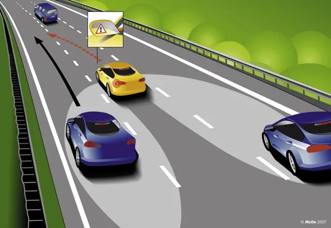
Drivers are educated to evaluate encompassing traffic prior to moving to another lane by checking their rearview and side mirrors and investigating each shoulder. Nonetheless, in any event, for the people who follow this succession of checks, the vehicle's vulnerable side - the region close by and simply behind the vehicle - is a steady wellspring of risk and frequently the reason for serious mishaps. Indeed, even vehicles drawing closer rapidly from behind can represent a gamble. To make moving to another lane more secure, this component has been created
Basic Working Guideline:
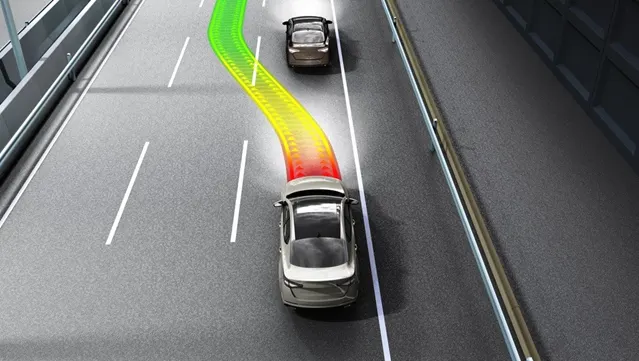
Thruway Colleague is a to some degree mechanized driving capability for a speed scope of up to 180 km/h (112 mph) on roadways. It joins the radar-based longitudinal direction of Versatile Journey Control (ACC) with the video-based sidelong direction of path-keeping support in one framework. Roadway Partner can be enhanced by a programmed path change started and observed by the driver in a speed scope of 60 - 130 km/h (35 - 80 mph).
The path Change Partner works by utilizing two mid-range radar sensors that are covered in the back guard - one on the left, and one on the right. These two sensors screen the region close by and behind the vehicle. Strong control programming groups the sensor data to make a total image of all traffic nearby behind the vehicle. Whenever another vehicle approaches at speed from behind or is as of now present on the vulnerable side, a sign, for example, an advance notice light in the side mirror makes the driver aware of the peril. Should the driver actually enact the blinker determined to switch to another lane, the framework gives an extra acoustic as well as haptic advance notice.
Model Development and Requirments:
Main Model: Highway Lane Assist
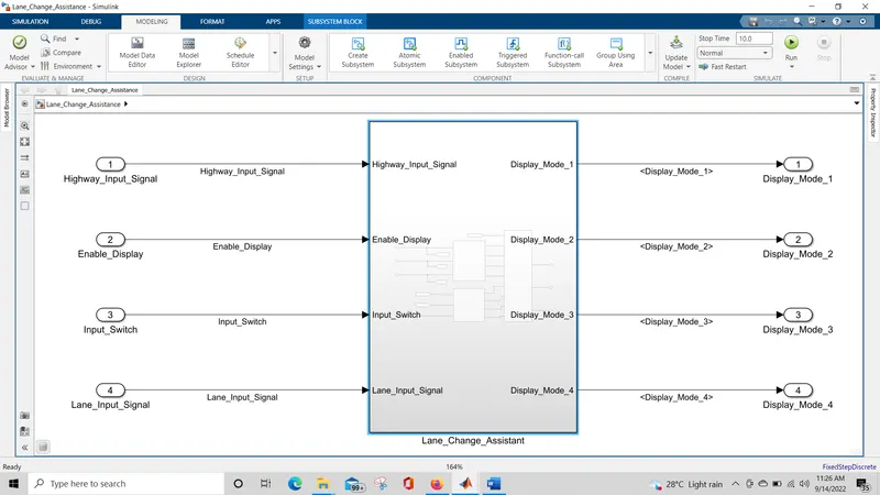
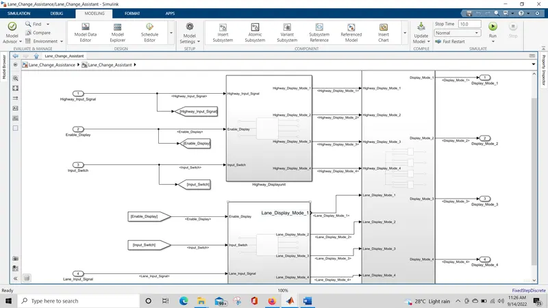
This Subsystem contain three inner subsystem which is requirement 1(Highway_DisplayUnit), 2(Lane_DisplayUnit) and 3(Display_ModelUnit).
R equ irement No 1 [Highway_DisplayUnit]:
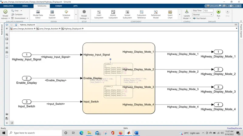
Inputs to this particular subsystem are “Highway_Input_Signal”, “Enable_Display”, “Input_Switch”. These three input signals, when assigned to a particular value will give output signals of specific value. The output signals
are “Highway_Display_Mode_1”, “Highway_Display_Mode_2”, “Highway_Display_Mode_3”, “Highway_Display_Mode_4”. The requirement must be implemented in the form of a Stateflow logic.
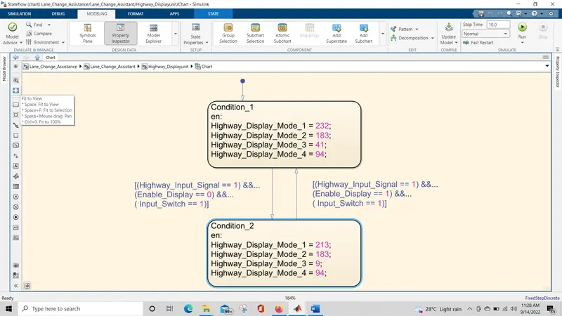
Condition Action
Highway_Display_Mode_1 = 232
Highway_Input_Signal = 1 Enable_Display = off Input_Switch = on
Highway_Input_Signal = 1 Enable_Display = on Input_Switch = on
Highway_Display_Mode_2 = 183
Highway_Display_Mode_3 = 41
Highway_Display_Mode_4 = 94
Highway_Display_Mode_1 = 213
Highway_Display_Mode_2 = 183
Highway_Display_Mode_3 = 9
Highway_Display_Mode_4 = 94
Implementation of requirment 1(Highway_DispalyUnit)
R equ irement No 2 [Lane_DisplayUnit]:
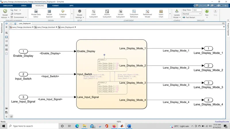
Inputs to this particular subsystem are “Enable_Display”, “Input_Switch”, and “Lane_Input_Signal”. These three input signals, when assigned to a particular value will give output signals of a specific value. The output signals
are “Lane_Display_Mode_1”, “Lane_Display_Mode_2”, “Lane_Display_Mode_3”, “Lane_Display_Mode_4”. The requirement must be implemented in the form of Stateflow logic.
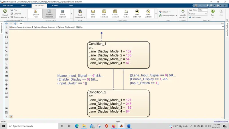
condition Action
Lane_Input_Signal= 6 Enable_Display = off Input_Switch = on
Lane_Display_Mode_1 = 132
Lane_Display_Mode_2 = 185
Lane_Display_Mode_3 = 54
Lane_Display_Mode_4 = 67
Lane_Input_Signal= 6 Enable_Display = on Input_Switch = on
Lane_Display_Mode_1 = 127
Lane_Display_Mode_2 = 248
Lane_Display_Mode_3 = 186
Lane_Display_Mode_4 = 84
Implementation of requirment 2(Lane_DispalyUnit)
 .
.
Requirement No 3:
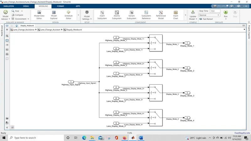
Signals coming from both subsystems “Highway_Display_Mode_1” & “Lane_Display_Mode_1” are given as inputs to a switch block which will have input signal “Highway_Input_Signal” given as 2nd input to the switch block. Corresponding output from this particular switch block is the output signal “Display_Mode_1”.
Signals coming from both subsystems “Highway_Display_Mode_2” & “Lane_Display_Mode_2” are given as inputs to a switch block which will have input signal “Highway_Input_Signal” given as 2nd input to the switch block. Corresponding output from this particular switch block is the output signal “Display_Mode_2”.
Signals coming from both subsystems “Highway_Display_Mode_3” & “Lane_Display_Mode_3” are given as inputs to a switch block which will have input signal “Highway_Input_Signal” given as 2nd input to the switch block. Corresponding output from this particular switch block is the output signal “Display_Mode_3”.
Signals coming from both subsystems “Highway_Display_Mode_4” & “Lane_Display_Mode_4” are given as inputs to a switch block which will have input signal “Highway_Input_Signal” given as 2nd input to the switch block. Corresponding output from this particular switch block is the output signal “Display_Mode_4”.
Implementation of requirment 3
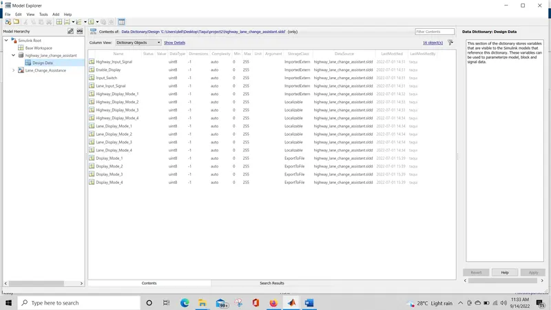
Simulink Data Dictionary] SLDD:
For connecting model signals and parameters we need to create an SLDD file so here we created an SLDD file with Simulink Model File.
Which have all the calibration and data used in the model.
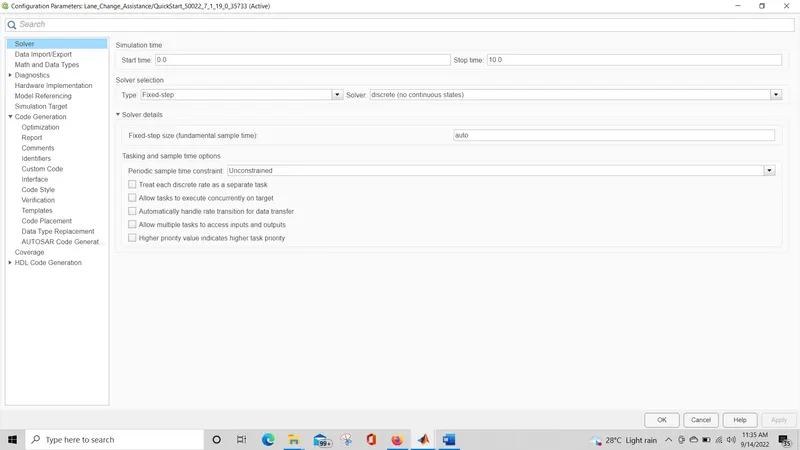
Now, for AUTOSAR Code generation we need to change the solver settings and Code generation settings. instead of variable step we need to put Fixed step and in Solver we need to put Discrete Solver.
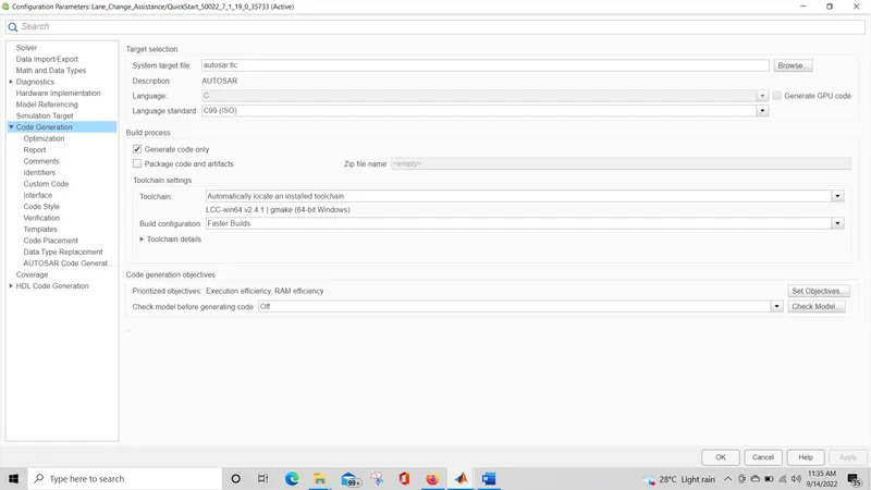
In the Code generation profile, we need to set it as "autosar.tlc" under the system target file.
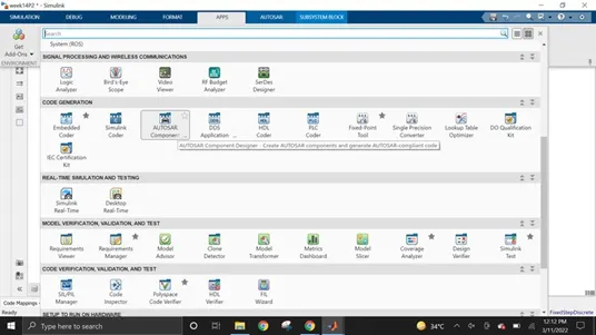
To configure AUTOSAR components in the AUTOSAR dictionary and generate AUTOSAR compliant Code, in The Under App Section, AUTOSAR component Designer is Selected.
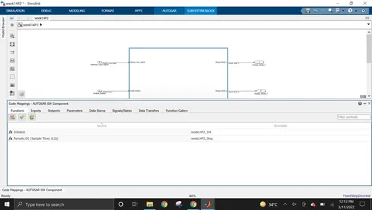
AUTOSAR dictionary can be accessed under code mappings - AUTOSAR SW Component section.
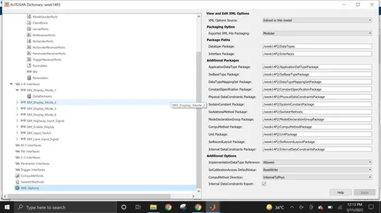
so, In AUTOSAR Dictionary first, I chose XML options and Specified the package paths.
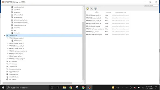
Sender receiver interfaces(SRIf) are configured next.
A total of eight sender-receiver interfaces will be created as there are four inputs and four outputs for the main subsystem 'Lane_Change_Assistance'
each sender-receiver interface is prefixed with SRIf_
The corresponding Data Element(DE_) of each SRIf is also renamed with DE_
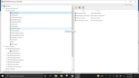
prefix Rp_(Receiver Port) is used before Receiver Ports signal names.
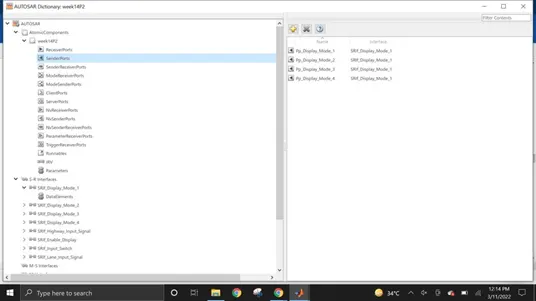
prefix Pp_(Provider Port) is used before Sender Ports signal names.
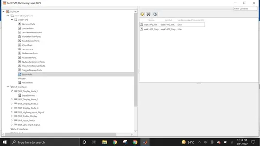
After Configuring XML options, SRIf, sender and receiver ports the runnable are configured next. two runnable are created one for the intialization event and another for the timing event.
After configuring all required data in the AUTOSAR dictionary, the Imports and Outports of the developed model are mapped to their corresponding receiver/sender ports and data elements.
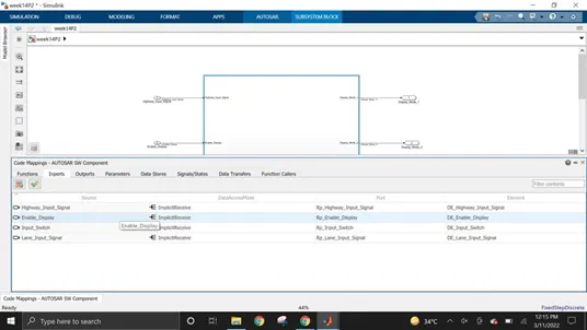
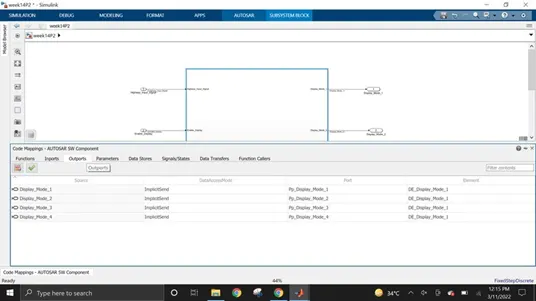
So, here we can see that code mapping are updated and validated as the final step to make sure all ports are mapped correctly.
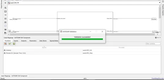
So, after generating the AUTOSAR dictionary we need to check the Model advisor report.
here we are checking the model advisor for the Modeling Standards For MAB(Mathworks Advisory Board)
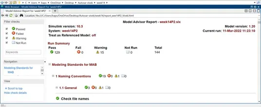
so we can see that we passed all the checks without any failure and I also tried to reduce no. of warnings.
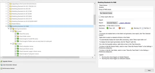
Model Advisor Report for MAB Guidelines:
Autosar Compliant Code generation:
For generating AUTOSAR Code we need to go into the AUTOSAR tab
where we find the "Quick start" option which we need to select for AUTOSAR Code generation.
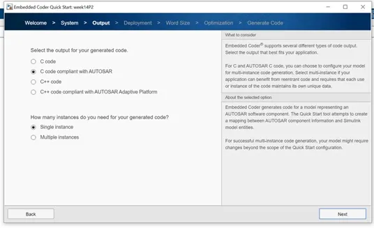
The quick start option will automatically manage model configuration settings to generate code. the code generation folder will contain generated .c, .h, .ARXML Files.
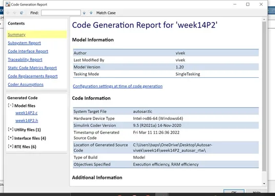
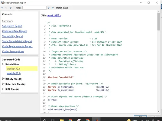
AUTOSAR Compliant C CODE:
/*
*	File: week14P2.c
*
*	Code generated for Simulink model 'week14P2'.
*
*	Model version	: 1.20
*	Simulink Coder version	: 9.5 (R2021a) 14-Nov-2020
*	C/C++ source code generated on : Fri Mar 11 11:26:36 2022
*
*	Target selection: autosar.tlc
*	Embedded hardware selection: Intel->x86-64 (Windows64)
*	Code generation objectives:
*	1. Execution efficiency
*	2. RAM efficiency
*	Validation result: Not run
*/

#include "week14P2.h"

/* Named constants for Chart: '/Chart' */
#define IN_Condition1	((uint8)1U)
#define IN_Condition2	((uint8)2U)

/* Block signals and states (default storage) */ DW rtDW;

/* Model step function */ void week14P2_Step(void)
{
sint32 tmp;
uint8 rtb_Highway_Display_Mode_1; uint8 rtb_Highway_Display_Mode_3; uint8 rtb_Lane_Display_Mode_1;
uint8 rtb_Lane_Display_Mode_2; uint8 rtb_Lane_Display_Mode_3; uint8 rtb_Lane_Display_Mode_4;

/* Chart: '/Chart' incorporates:
*	Inport: '/Enable_Display'
*	Inport: '/Highway_Input_Signal'
*	Inport: '/Input_Switch'
*/
if (rtDW.is_active_c3_week14P2 == 0U) { rtDW.is_active_c3_week14P2 = 1U;
rtDW.is_c3_week14P2 = IN_Condition1; rtb_Highway_Display_Mode_1 = 232U;
rtb_Highway_Display_Mode_3 = 41U;
} else if (rtDW.is_c3_week14P2 == IN_Condition1) { rtb_Highway_Display_Mode_1 = 232U;
rtb_Highway_Display_Mode_3 = 41U;
if ((Rte_IRead_week14P2_Step_Rp_Highway_Input_Signal_DE_Highway_Input_Signal () == 1) &&
(Rte_IRead_week14P2_Step_Rp_Enable_Display_DE_Enable_Display() == 1) && (Rte_IRead_week14P2_Step_Rp_Input_Switch_DE_Input_Switch() == 1)) {
rtDW.is_c3_week14P2 = IN_Condition2; rtb_Highway_Display_Mode_1 = 213U;
rtb_Highway_Display_Mode_3 = 9U;
}
} else {
/* case IN_Condition2: */
rtb_Highway_Display_Mode_1 = 213U; rtb_Highway_Display_Mode_3 = 9U;
if ((Rte_IRead_week14P2_Step_Rp_Highway_Input_Signal_DE_Highway_Input_Signal () == 1) &&
(Rte_IRead_week14P2_Step_Rp_Enable_Display_DE_Enable_Display() == 0) && (Rte_IRead_week14P2_Step_Rp_Input_Switch_DE_Input_Switch() == 1)) {
rtDW.is_c3_week14P2 = IN_Condition1; rtb_Highway_Display_Mode_1 = 232U;
rtb_Highway_Display_Mode_3 = 41U;
}
}

/* End of Chart: '/Chart' */

/* End of Chart: '/Chart' */

/* Chart: '/Chart' incorporates:
*	Inport: '/Enable_Display'
*	Inport: '/Input_Switch'
*	Inport: '/Lane_Input_Signal'
*/
if (rtDW.is_active_c1_week14P2 == 0U) { rtDW.is_active_c1_week14P2 = 1U;
rtDW.is_c1_week14P2 = IN_Condition1; rtb_Lane_Display_Mode_1 = 132U;
rtb_Lane_Display_Mode_2 = 185U; rtb_Lane_Display_Mode_3 = 54U; rtb_Lane_Display_Mode_4 = 67U;
} else if (rtDW.is_c1_week14P2 == IN_Condition1) { rtb_Lane_Display_Mode_1 = 132U;
rtb_Lane_Display_Mode_2 = 185U; rtb_Lane_Display_Mode_3 = 54U; rtb_Lane_Display_Mode_4 = 67U;
if ((Rte_IRead_week14P2_Step_Rp_Lane_Input_Signal_DE_Lane_Input_Signal() ==
6)	&& (Rte_IRead_week14P2_Step_Rp_Enable_Display_DE_Enable_Display() ==
1)	&& (Rte_IRead_week14P2_Step_Rp_Input_Switch_DE_Input_Switch()
== 1)) {
rtDW.is_c1_week14P2 = IN_Condition2; rtb_Lane_Display_Mode_1 = 127U;
rtb_Lane_Display_Mode_2 = 248U; rtb_Lane_Display_Mode_3 = 186U; rtb_Lane_Display_Mode_4 = 84U;
}
} else {
/* case IN_Condition2: */
rtb_Lane_Display_Mode_1 = 127U; rtb_Lane_Display_Mode_2 = 248U;
rtb_Lane_Display_Mode_3 = 186U; rtb_Lane_Display_Mode_4 = 84U;
if ((Rte_IRead_week14P2_Step_Rp_Lane_Input_Signal_DE_Lane_Input_Signal() ==
6) && (Rte_IRead_week14P2_Step_Rp_Enable_Display_DE_Enable_Display() ==
0) && (Rte_IRead_week14P2_Step_Rp_Input_Switch_DE_Input_Switch()
== 1)) {
rtDW.is_c1_week14P2 = IN_Condition1; rtb_Lane_Display_Mode_1 = 132U;
rtb_Lane_Display_Mode_2 = 185U; rtb_Lane_Display_Mode_3 = 54U; rtb_Lane_Display_Mode_4 = 67U;
}
}

/* End of Chart: '/Chart' */

/* Switch: '/Switch' incorporates:
*	Inport: '/Highway_Input_Signal'
*	Switch: '/Switch1'
*	Switch: '/Switch2'
*/
tmp = Rte_IRead_week14P2_Step_Rp_Highway_Input_Signal_DE_Highway_Input_Signal(); if (tmp != 0) {
/* Outport: '/Display_Mode_1' */
Rte_IWrite_week14P2_Step_Pp_Display_Mode_1_DE_Display_Mode_1 (rtb_Highway_Display_Mode_1);
rtb_Lane_Display_Mode_2 = 183U;
} else {
/* Outport: '/Display_Mode_1' */
Rte_IWrite_week14P2_Step_Pp_Display_Mode_1_DE_Display_Mode_1 (rtb_Lane_Display_Mode_1);
}

/* End of Switch: '/Switch' */

/* Outport: '/Display_Mode_2' */
Rte_IWrite_week14P2_Step_Pp_Display_Mode_2_DE_Display_Mode_1 (rtb_Lane_Display_Mode_2);

/* Switch: '/Switch2' incorporates:
*	Switch: '/Switch3'
*/
if (tmp != 0) {
/* Outport: '/Display_Mode_3' */
Rte_IWrite_week14P2_Step_Pp_Display_Mode_3_DE_Display_Mode_1 (rtb_Highway_Display_Mode_3);
rtb_Lane_Display_Mode_4 = 94U;
} else {
/* Outport: '/Display_Mode_3' */
Rte_IWrite_week14P2_Step_Pp_Display_Mode_3_DE_Display_Mode_1 (rtb_Lane_Display_Mode_3);
}

/* Outport: '/Display_Mode_4' */
Rte_IWrite_week14P2_Step_Pp_Display_Mode_4_DE_Display_Mode_1 (rtb_Lane_Display_Mode_4);
}

/* Model initialize function */ void week14P2_Init(void)
{
/* (no initialization code required) */
}

/*
*	File trailer for generated code.
*
*	[EOF]
*/
conclusion :
Thruway Path Right hand created in MATLAB Simulink according to MBD rules.
Code Age Profile is Autosar Coder.
Simulink Information Word reference made for the model and connected to the model.
All the information and result signals planned into the Autosar Manager.
Model Guide Report is Produced and this will be trailed by Code Age.
Every one of the significant Records like model, Code Report, SLDD document, Model Counsel report are Appended.