Project 2 - Development of TFT Cluster Speedometer Software Component
TFT Cluster Speedometer Software:
- Procedure to solve the problem statement
- Developing the Simulink model as per the problem statement given above.
-
Explanation of the Simulink model:
- The main subsystem will have four inputs (In_MainFilt_SpeedValue, In_AuxillaryFilt_SpeedValue, Avg_VehicleSpeed, Timer_Input) and one output (Out_VehicleSpeedDisplay)
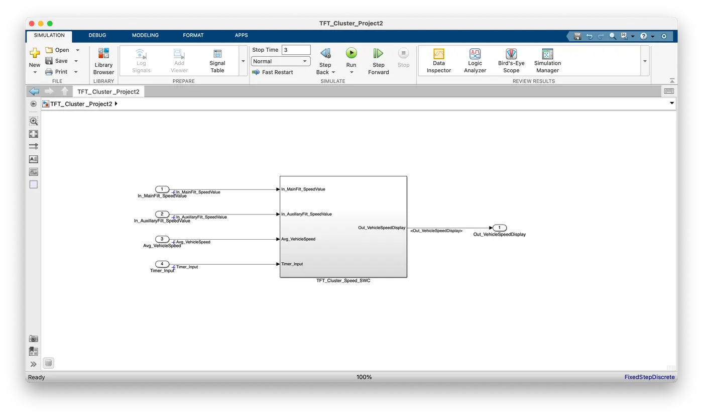
- Inside the main subsystem, we have 4 other subsystems. They are Input_Processing, Main_Data_Filtering, Auxillary_Data_Filtering, and TFT_Speed_Output.
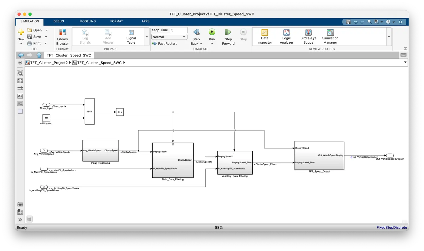
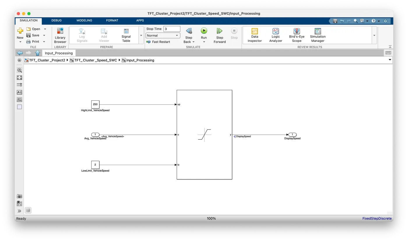
- Inside the input processing, we are saturating the Avg_VehicleSpeed within 250 kmph and 2 kmph. If the Avg_VehicleSpeed is greater than 250 kmph then the output DisplaySpeed will be saturated to 250 kmph. If Avg_VehicleSpeed is less than 2 kmph then the output DisplaySpeed will be saturated to 2 kmph. Else, the output DisplaySpeed will be the same as Avg_VehicleSpeed.
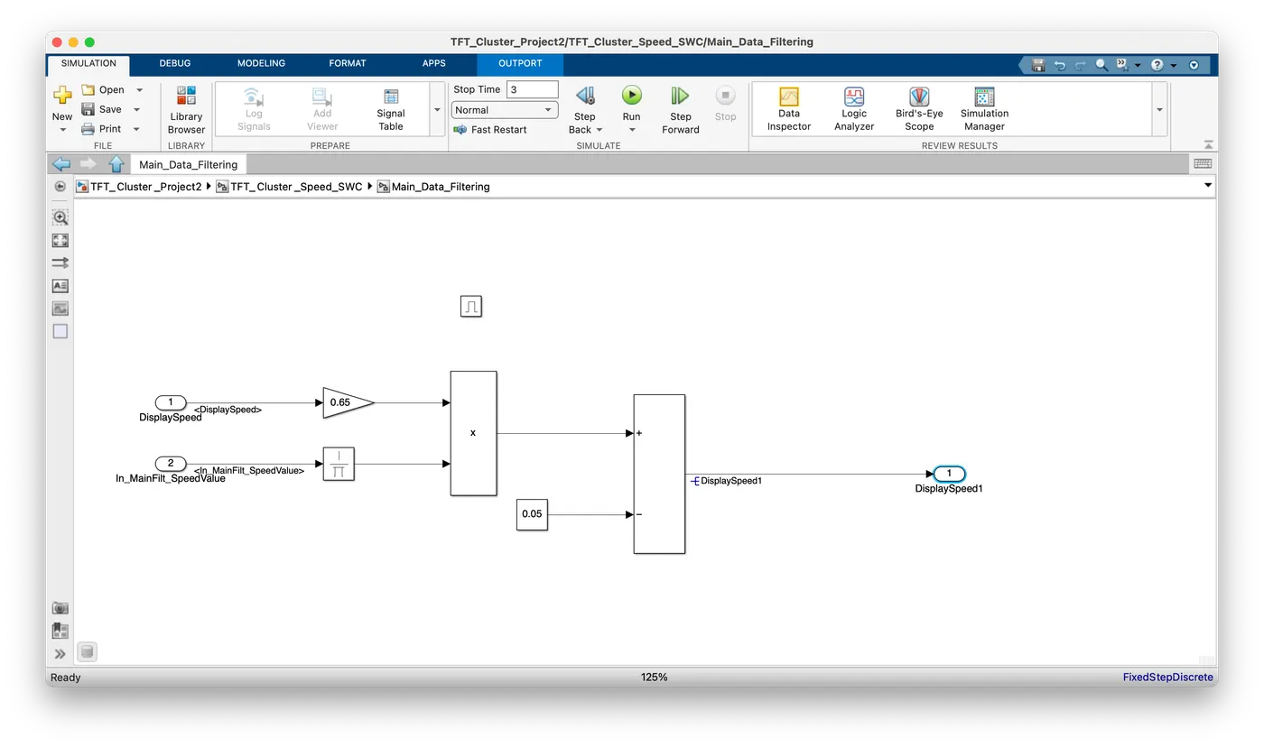
- Main_Data_Filtering: By using the formula, DisplaySpeed1 (t) = ((DisplaySpeed (t) x 0.65)/ Main Filter Speed Value) - 0.05, we find the value of DisplaySpeed1 output. Here the inputs are DisplaySpeed and In_MainFilt_SpeedValue.
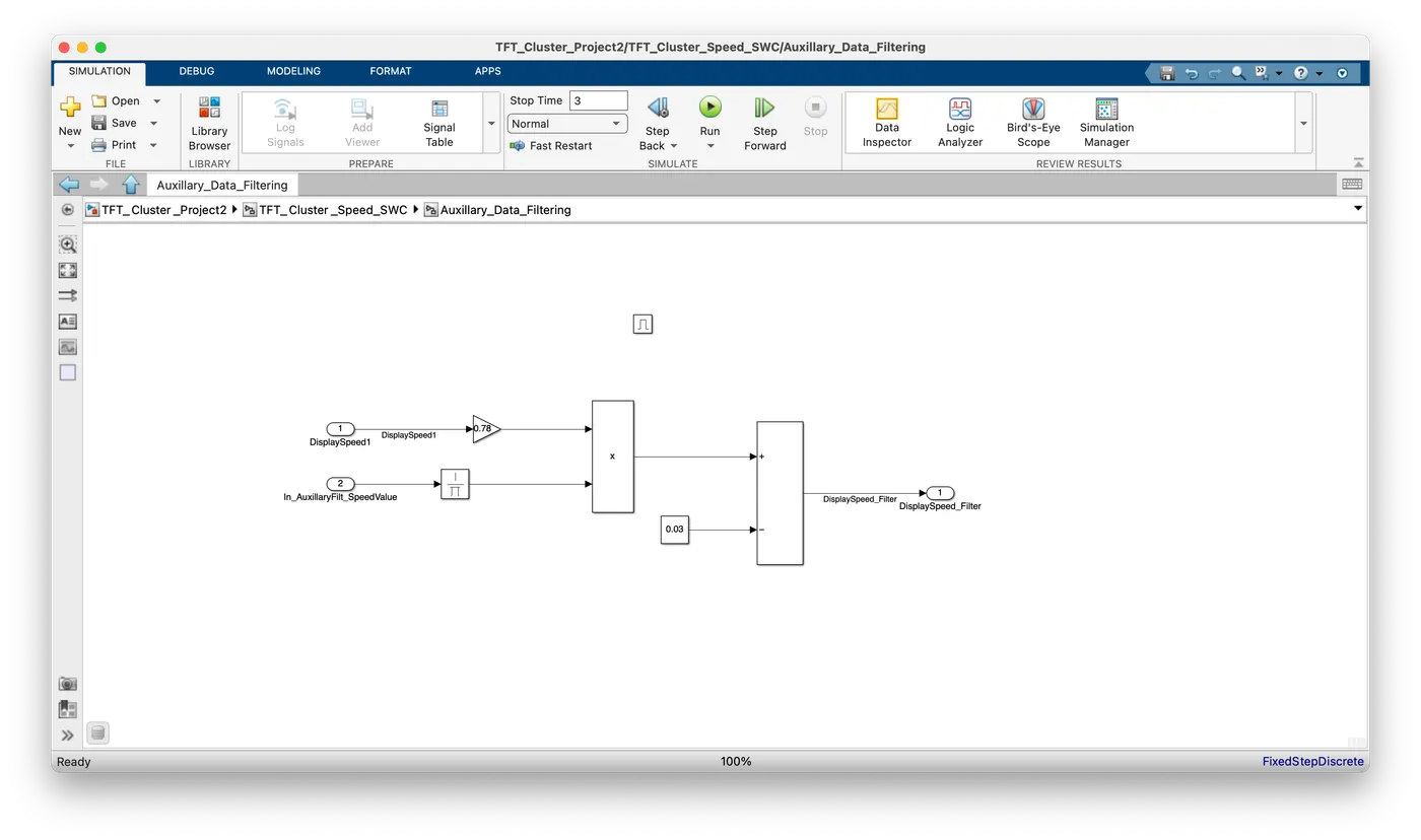
- Auxillary_Data_Filtering: By using the formula, DisplaySpeed_Filter (t) = ((DisplaySpeed1 (t) x 0.78)/ Auxillary Filter Speed Value) - 0.03, we find the value of DisplaySpeed_Filter output. Here the inputs are DisplaySpeed1 and In_AuxillaryFilt_SpeedValue.
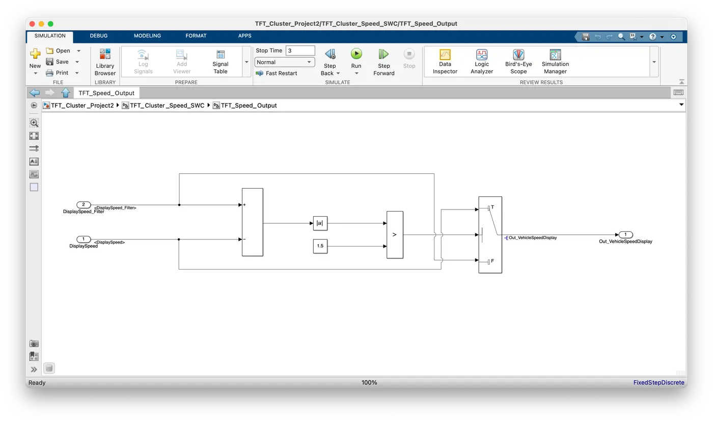
- TFT_Speed_Output: By using the logic,
we find the value of Out_VehicleSpeedDisplay output. Here the inputs are DisplaySpeed_Filter and DisplaySpeed.If |(DisplaySpeedFilter - DisplaySpeed)| > 1.5
{
Vehicle Speed Display = DisplaySpeed
}
else
{
Vehicle Speed Display = DisplaySpeed Filter
}
-
SLDD of the Simulink model:
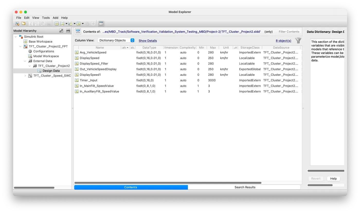
- In_MainFilt_SpeedValue, In_AuxillaryFilt_SpeedValue, Avg_VehicleSpeed, and Timer_Input are the sensor in the car and Out_VehicleSpeedDisplay is an output parameter signal which will be given to the motor. We have prepared the SLDD for the same.
-
Requirement Tagging:
- Go to Apps -> click "Requirement editor" -> click "New Requirement Set"
- Save the requirement set
- Select the requirement set and click Add Requirement
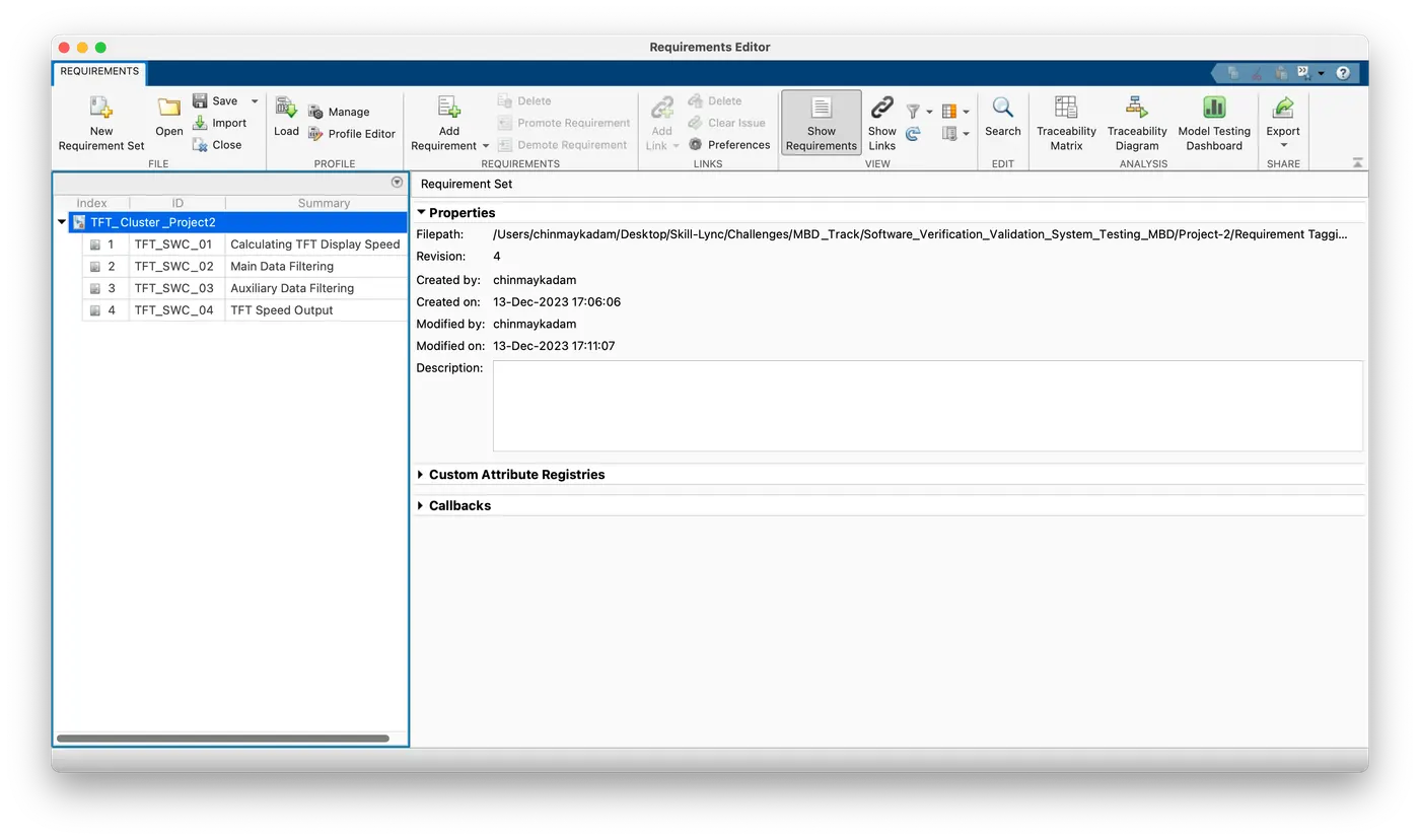
- In the Properties pane, we entered details for the requirement. In total, we added 3 requirements from the problem statement.
- Linked the requirements to their specified blocks by right-clicking the requirement and selecting Link from "object name"
-
Model Advisor Report:
- First "Run" the program without errors.
- Then click the "Model Advisor" tab from the "Modeling" section.
- Select the "modeling standards for JMAAB v5.1 and v6.0" and unselect everything else.
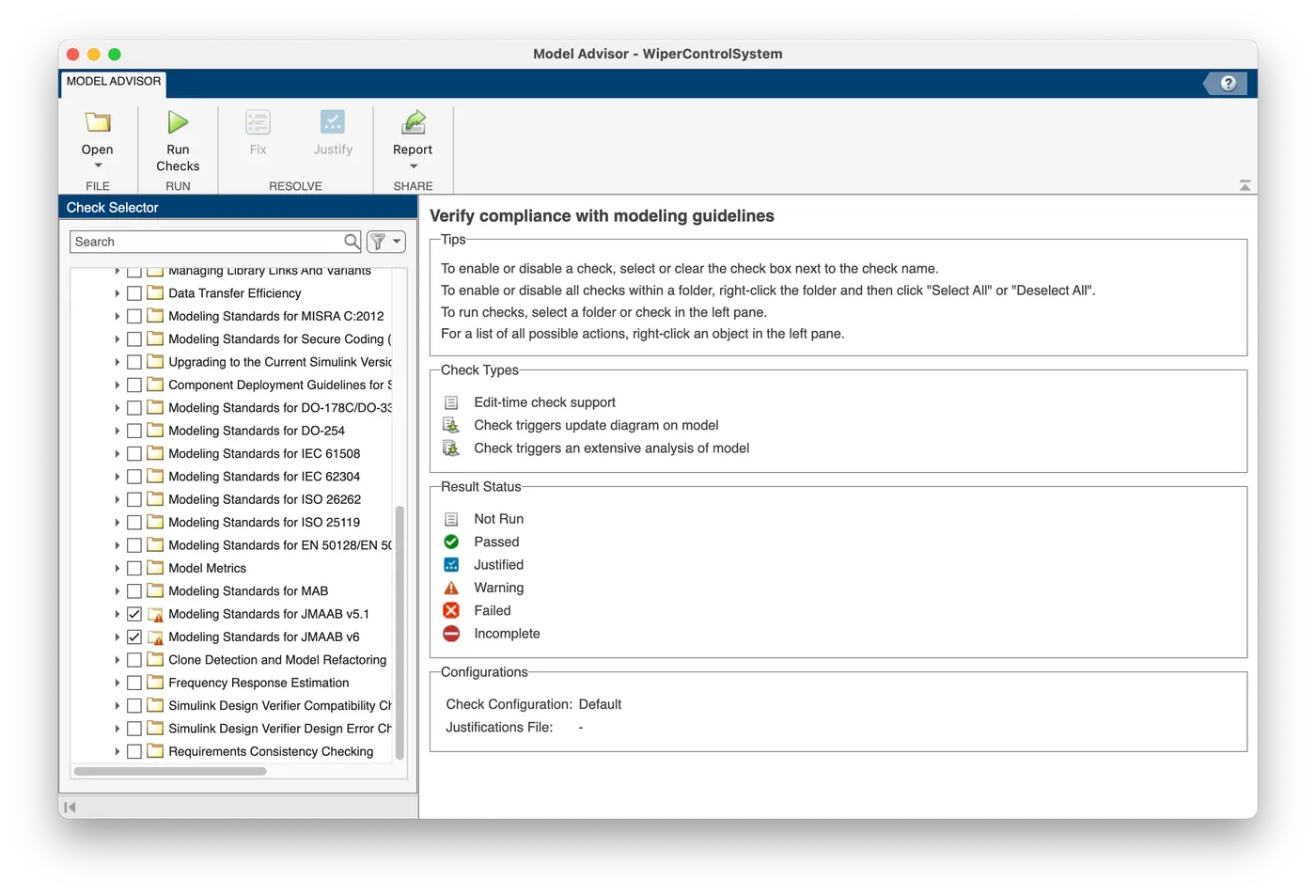
- Then press "Run checks" and try to clear the maximum warnings as possible.
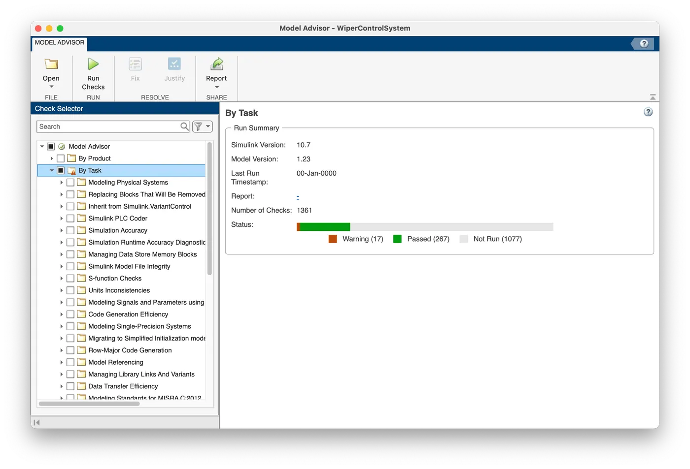
- Model Advisor Report is attached separately for the same.
-
Fixed Point Tool Test:
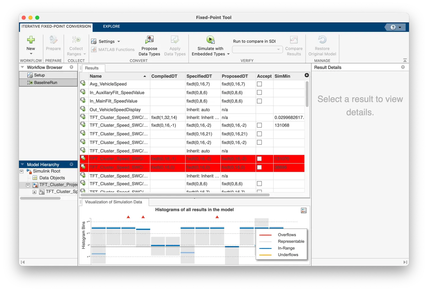
- Go to Apps -> click on "Fixed point tool"
- select "iterative fixed point conversion"
- Click "collect ranges"
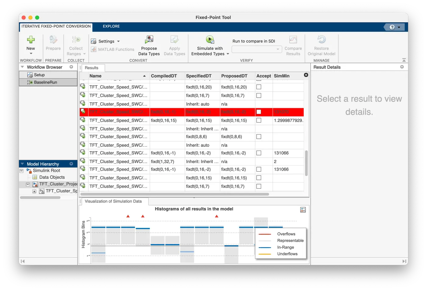
- Click "Propose data types" and one suggestion to change the data type for input RainDensity was suggested.
- Click "Apply datatypes"
-
SLDV Design Error Detection Report:
- Go to Apps and click "Design Verifier"
- Go to "Error detection settings" click "report" enable the option "Generate a report of the result" and click Apply
- Click "Detect Desing Errors" and a report is generated.
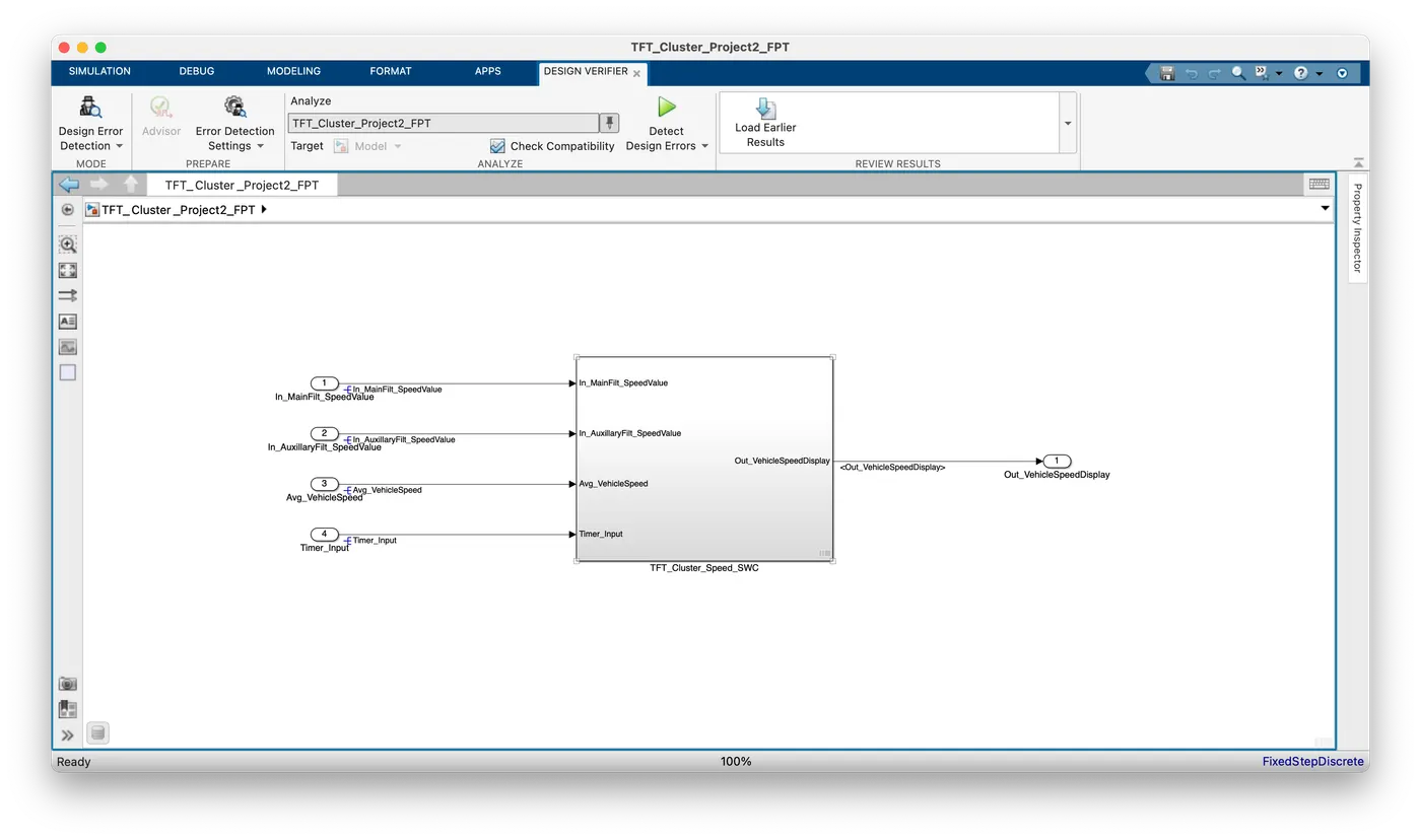
- The design Error Detection report is attached separately.
-
Coverage Report:
- Go to the modeling tab and click Model settings
- Go to coverage and enable the option "Enable coverage analysis"
- Click "Run ( Coverage)"
-
MIL:
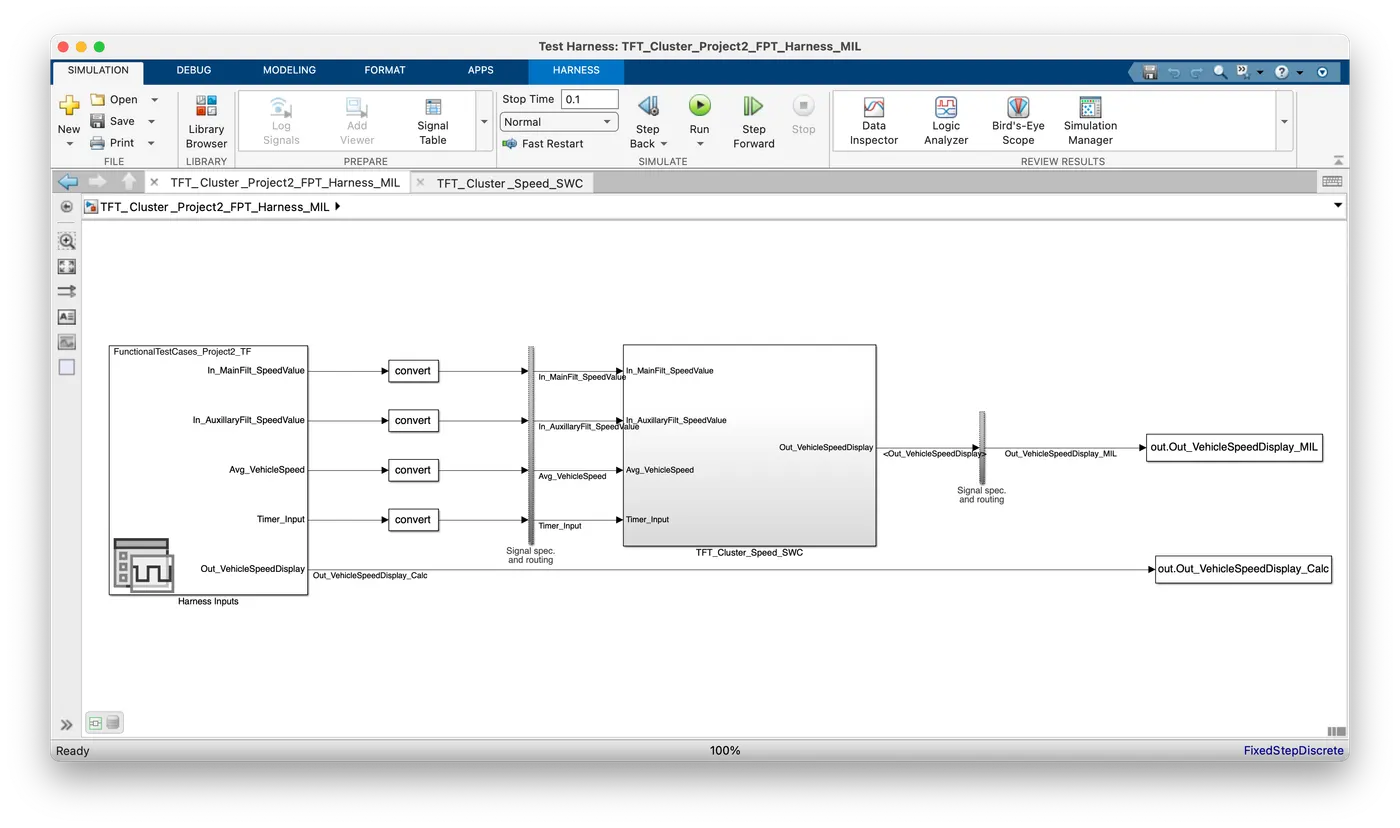
- Right-click on the main subsystem and create the harness
- Select "Signal builder" as the inport and "from workspace" as the outport
- Enable "create external harness of the model" and click apply
- This creates a separate harness.
- Now, click on the signal builder and inport the functional test case Excel file.
- This will create an extra output port from the signal builder. We take the output from this to a different workspace named "calculated wind velocity" and output from the harness has a workspace block named "MIL wind velocity".
- With the help of this, we can compare the values and observe that the same values are obtained from the model as calculated. This makes the MIL testing successful.
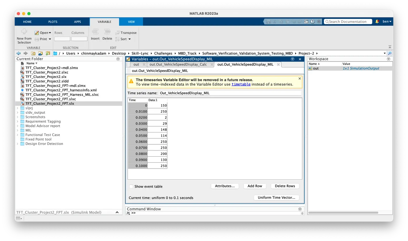
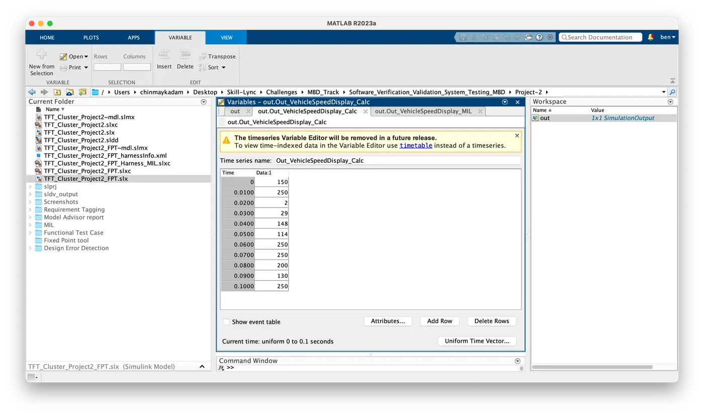
- The MIL & Data inspector report's coverage report is attached for your reference.
-
SLDV Test Generation:
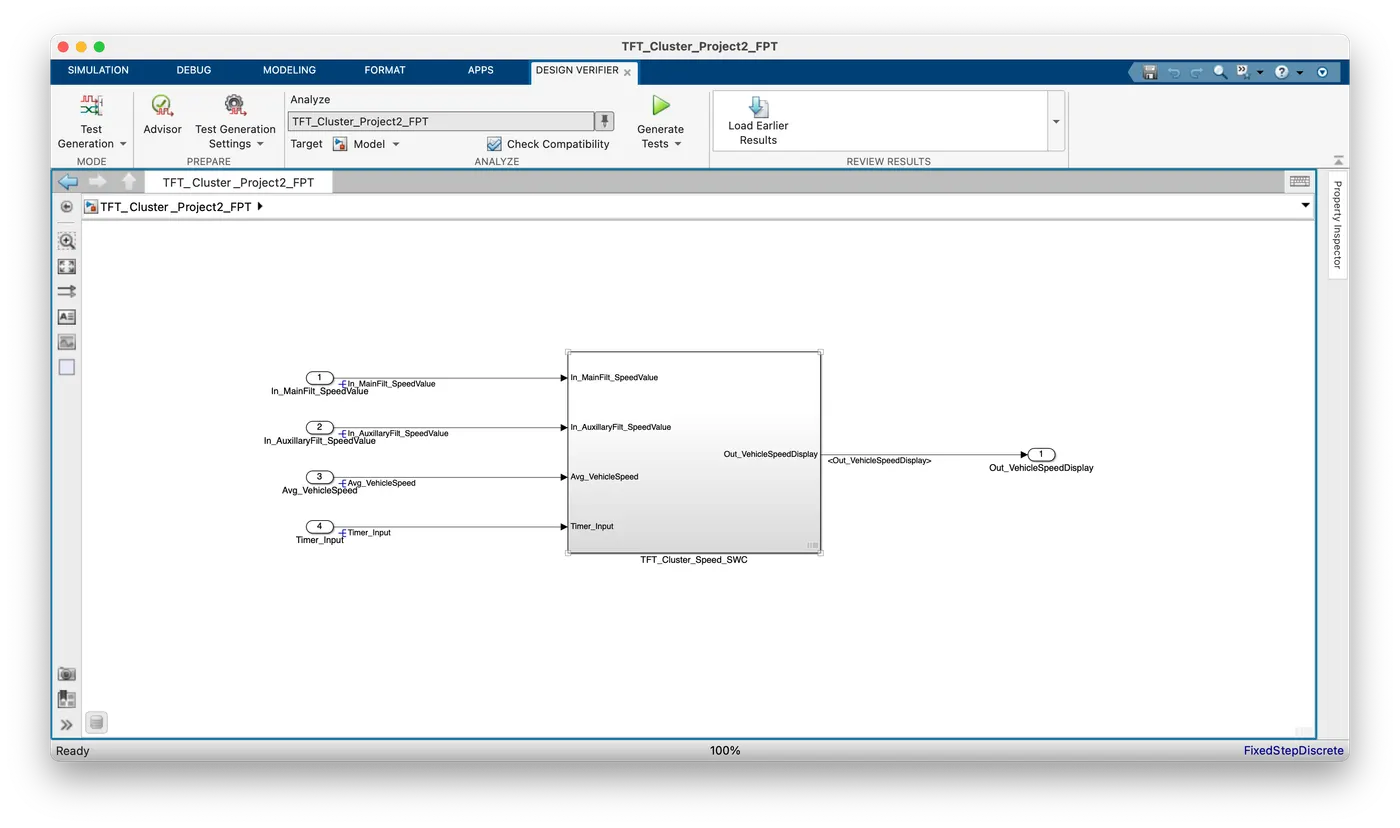
- Go to Apps and click "Design Verifier"
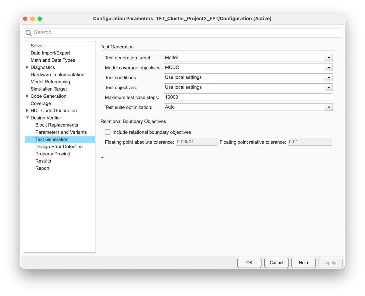
- Go to "Test Generation" select "MCDC" and click Apply
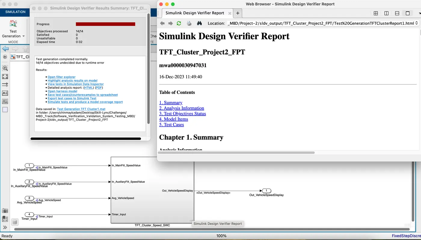
- Click "Test Generation" and a report is generated
- Result Summary & Test Generation Report:
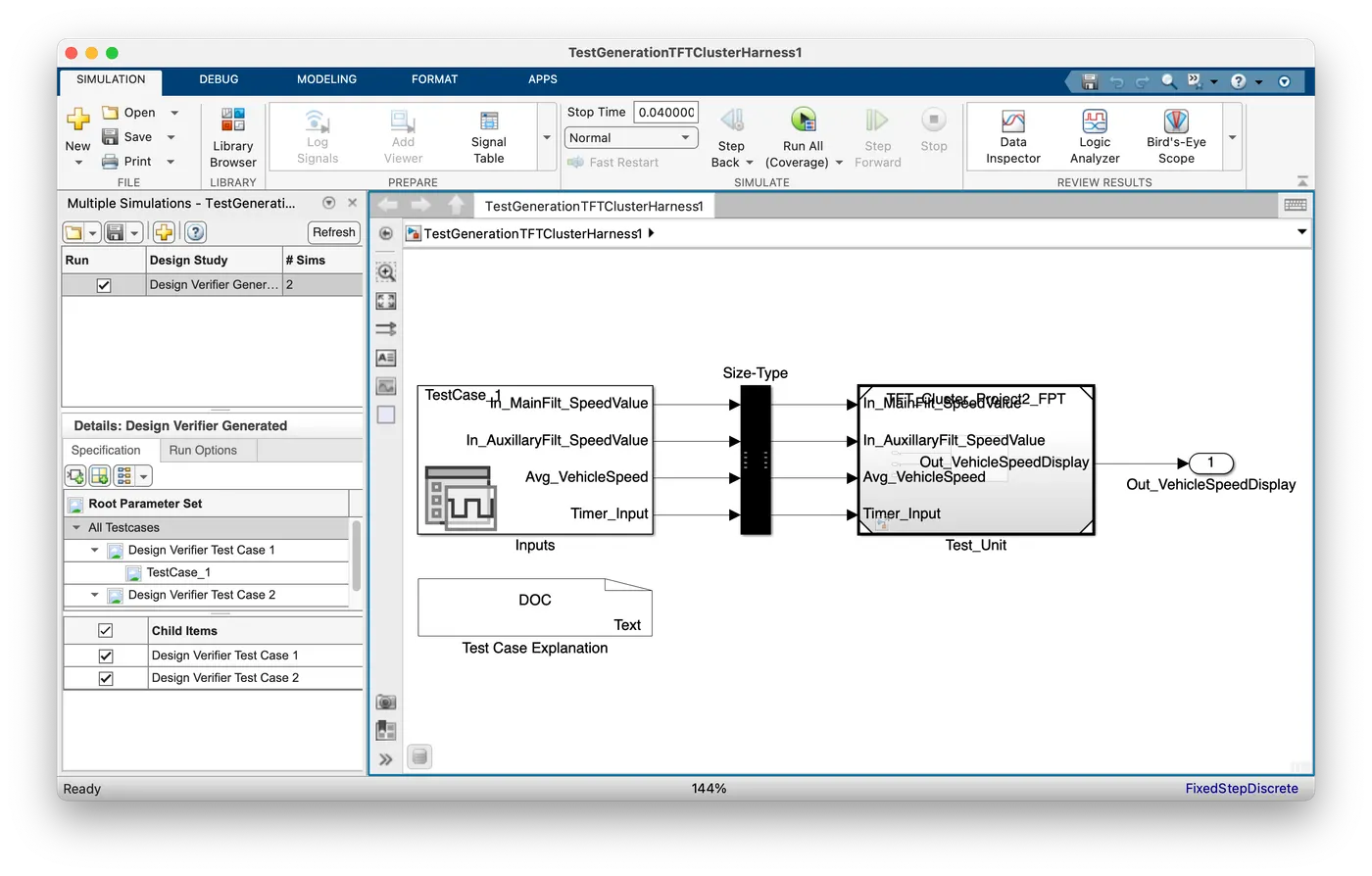
- Test Generation Harness:
-
Baseline Testing:
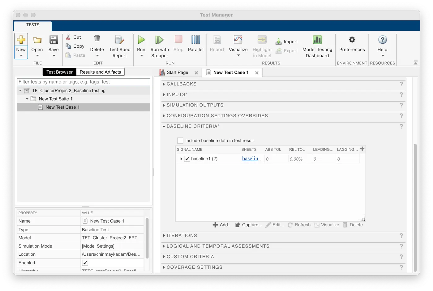
- Go to Apps -> "Simulink Test Manager" -> Click "New" -> Click "Test file"
- In the test file section fill in the details for the following tabs.
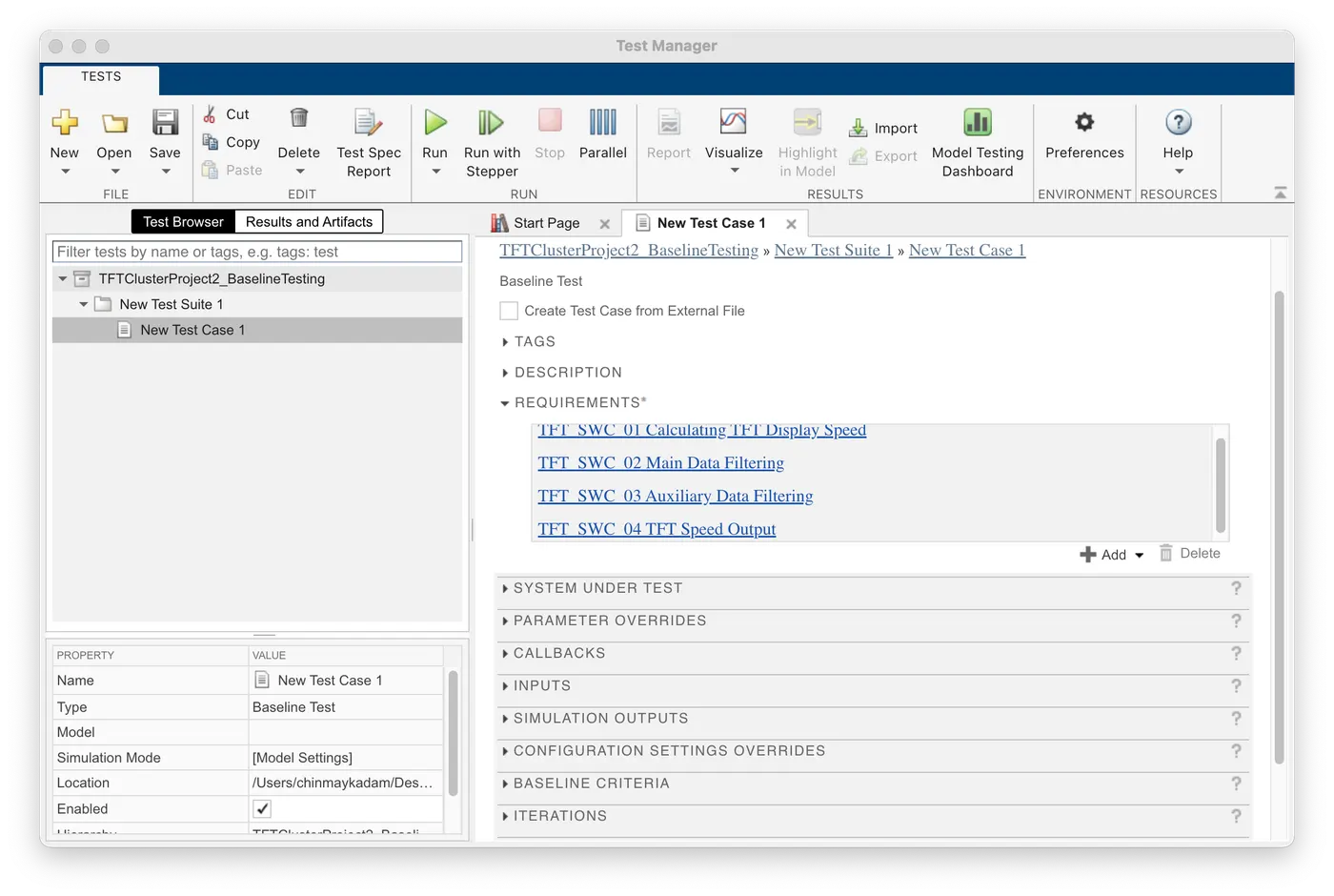
- Requirements: Add the slreq file to the requirements section by checking the requirement toolbox option inside the tab.
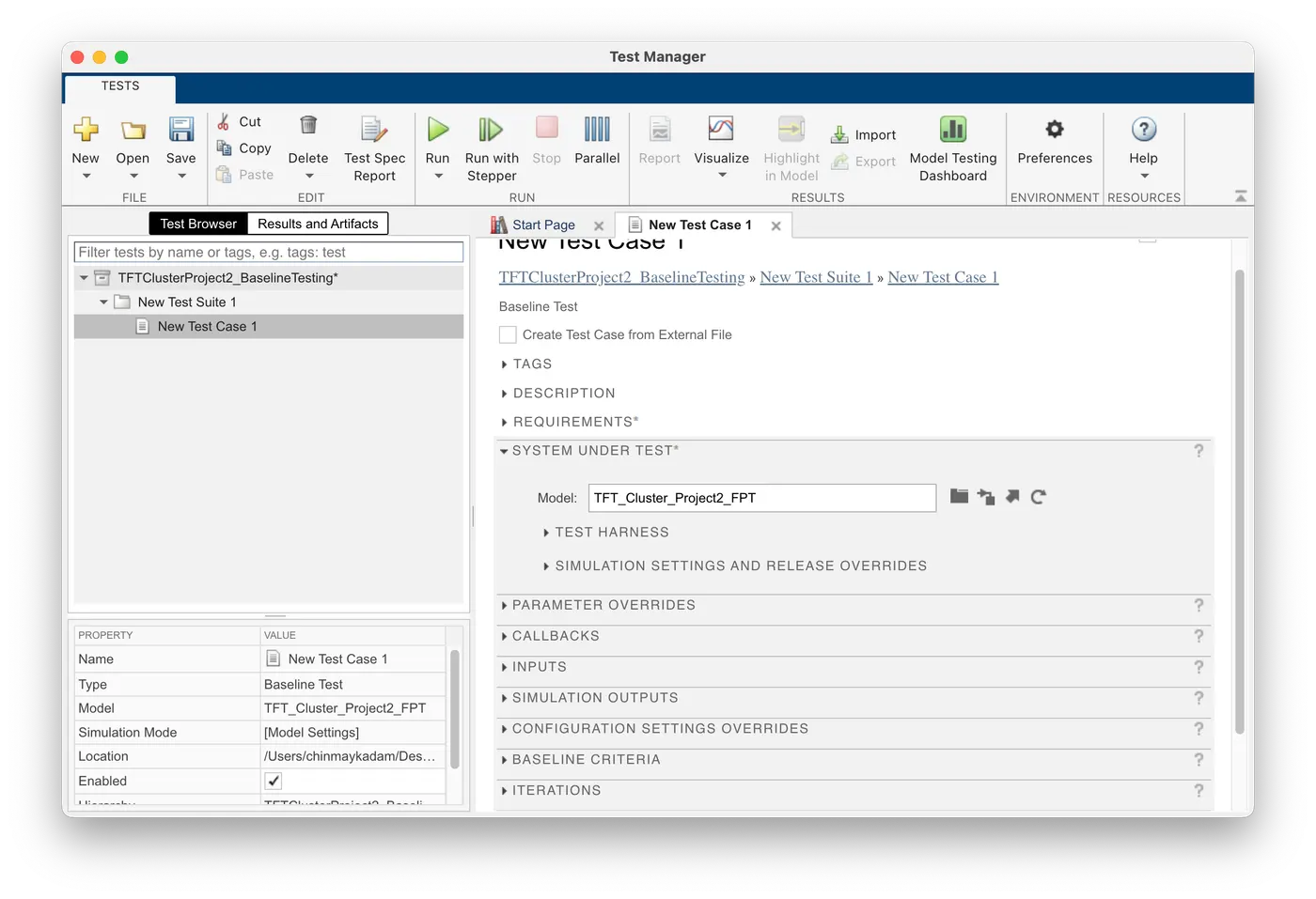
- Go to the next section "System under test". In this add the Simulink model .slx file to this section.
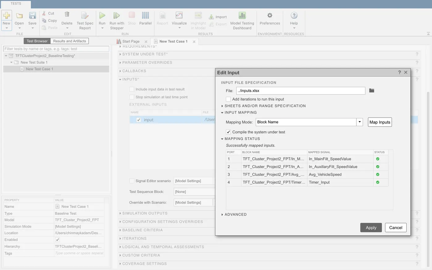
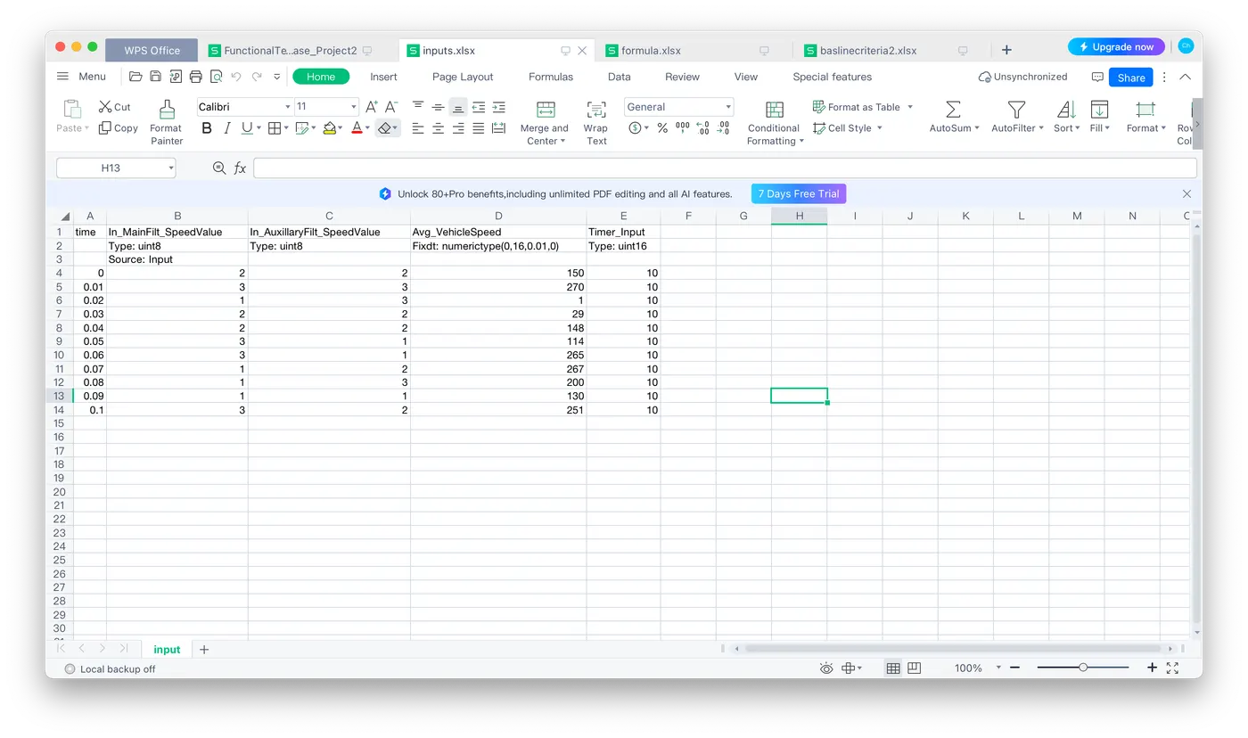
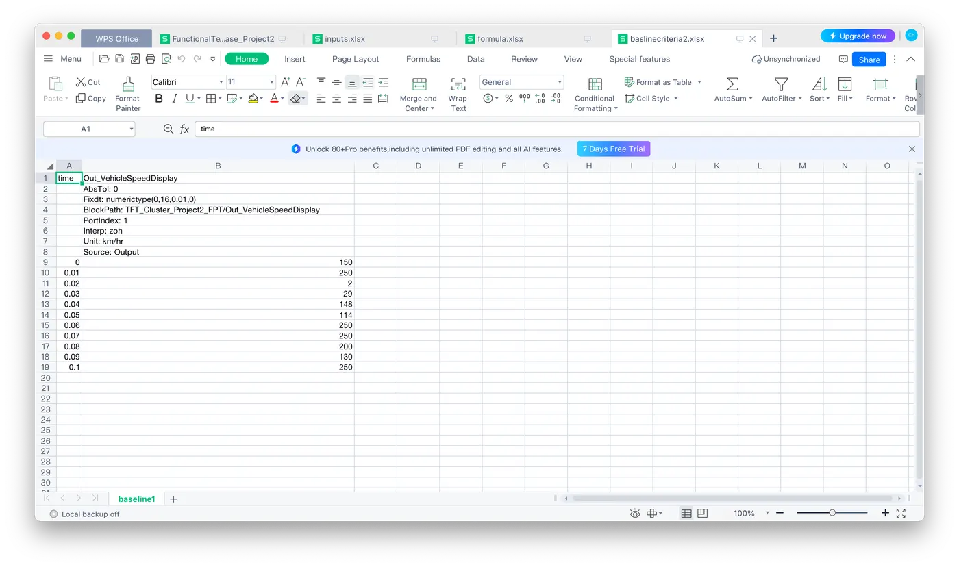
- Next, go to the inputs section and create an Excel sheet where all the input data or the input signals of the Simulink model are created.
- After creating the excel sheet, we have to manually enter all the input states we prepared in the functional test case file.
- Click the next section "Baseline Criteria". In this, we have to capture the time and output of the designed Simulink model inside an Excel sheet. Once, we click the capture button, an Excel sheet is created with the time and output data based on the modification done inside the inputs Excel sheet.
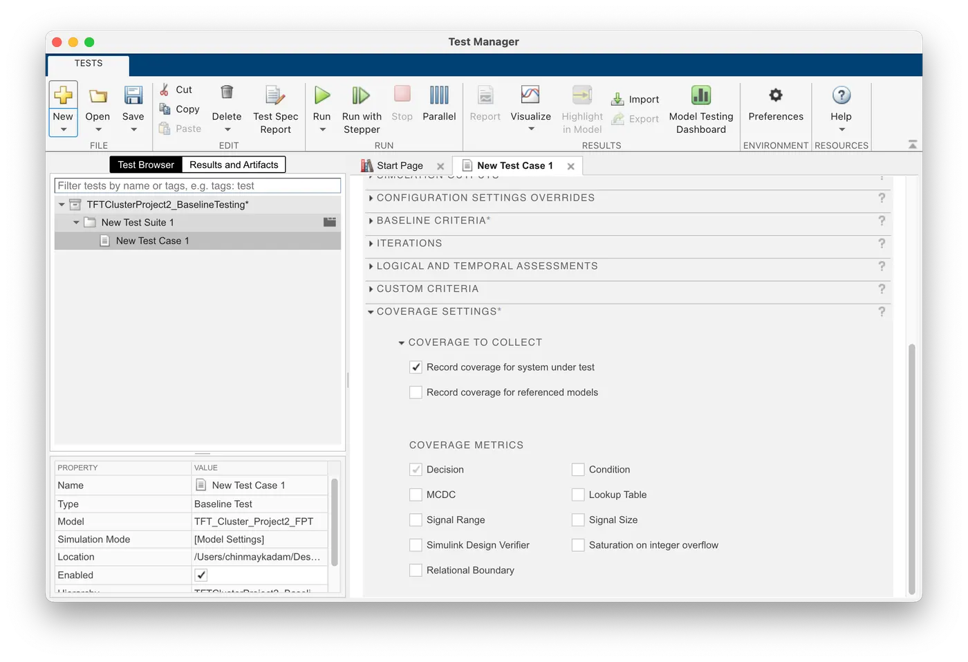
- Go to the next section "Coverage settings". Enable the "Record coverage system under test"
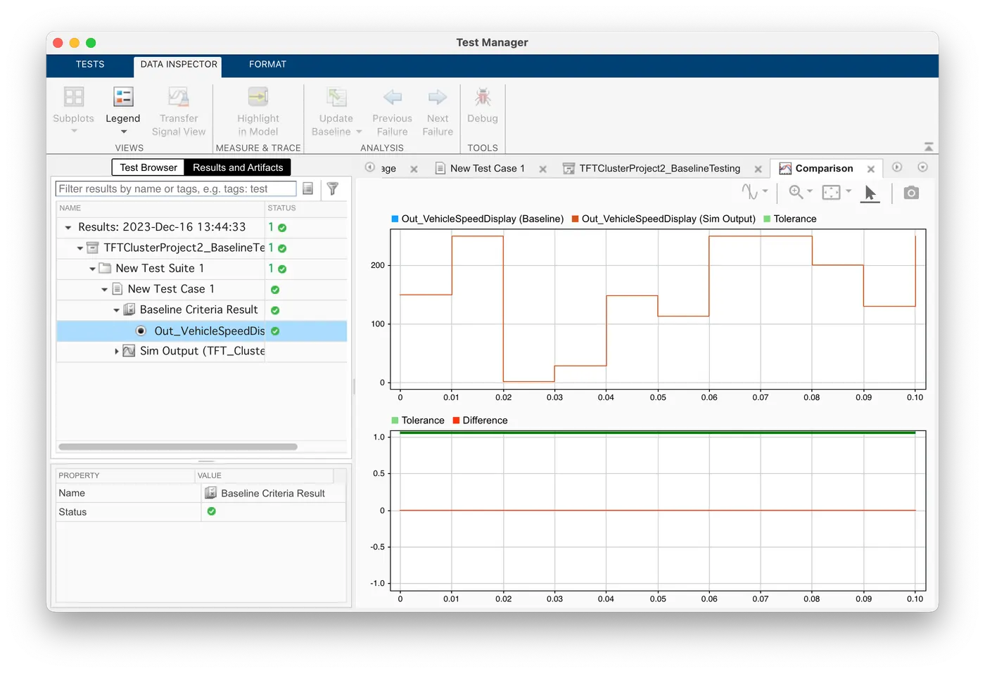
- After this, click RUN. Results are shown under the section "results and artifacts"
- A report is generated for Baseline testing.
-
Back to Back Testing:
- Open apps -> Go to "Simulink Tester" -> Go to "Simulink Test Manager"
- Test Manager window opens separately. Select New -> Test File -> Go back to the model and select the "Top Model" i.e the 1st subsystem of the model -> Comeback to the Test manager window and select New again -> Click "Test for component model"
- "Create Test for component model window opens" -> Click the "use current model" tab for the top model to be selected -> Click Next
- Test inputs -> Select the option with "Use Design Verifier to generate test input scenarios" and click Next
- Verification strategy -> Select "Perform back-to-back testing" and select Normal for simulation.1 and SIL for simulation 2. Also, enable "Set Model coverage objectives as Enhanced MCDC"
- Generated test -> Select input source as "Inports" and file format as "Excel" -> Click Done
- Two harnesses were created. Normal harness and SIL harness.
- Result:
- Harness Creation after running the Back to Backtesting
- Normal Harness
- SIL Harness
-
SIL Testing:
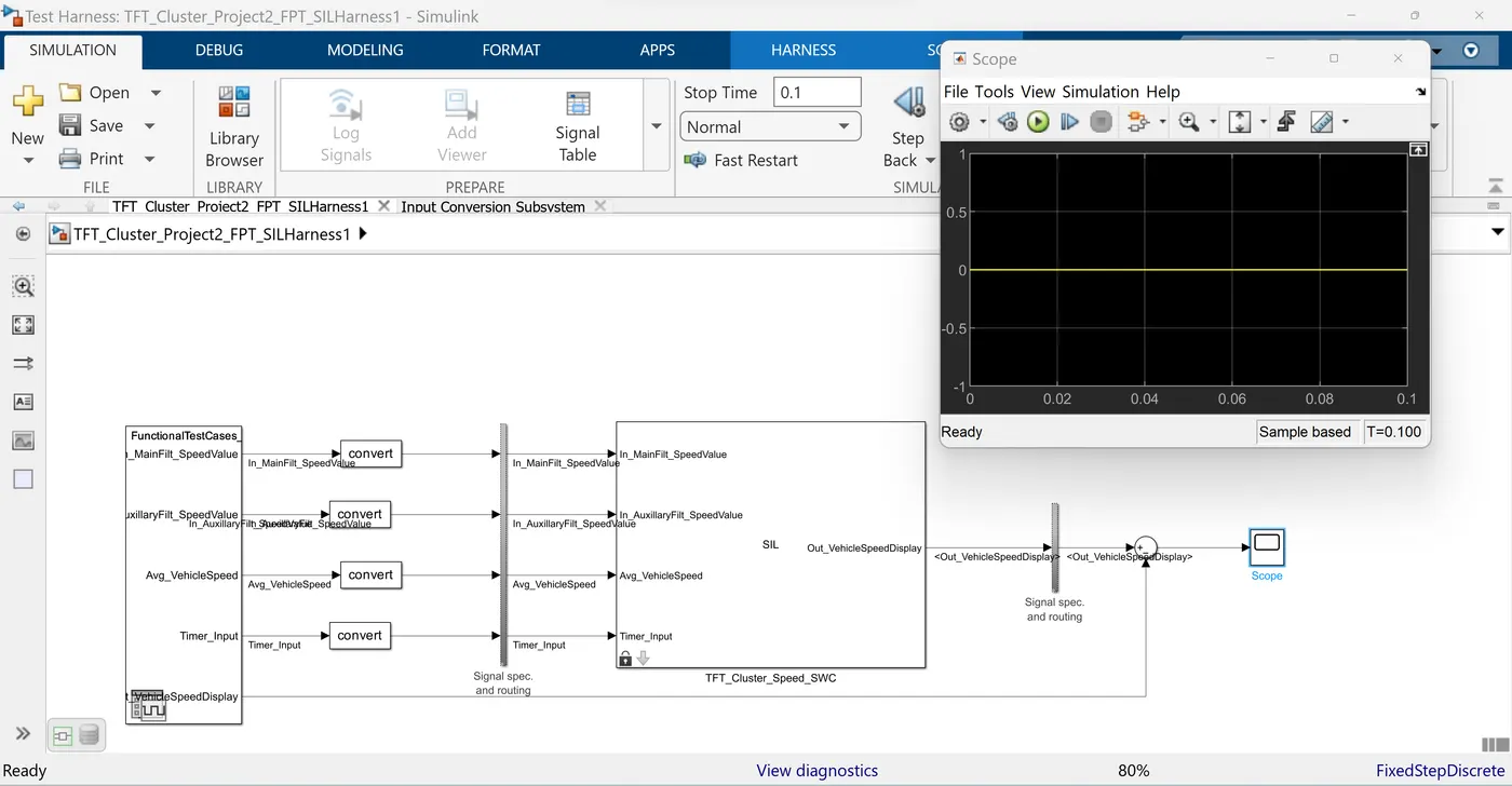
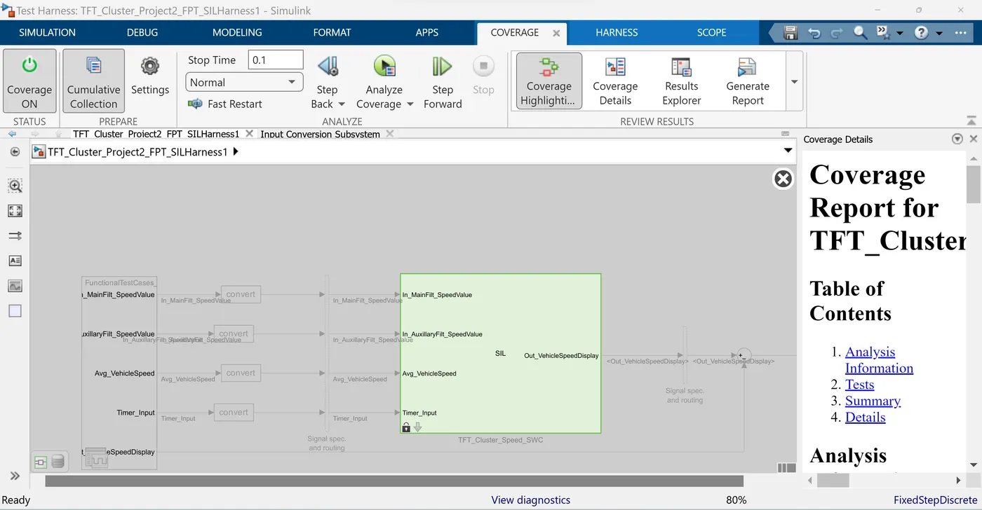
- Harness for SIL is made by right-clicking the subsystem and selecting Create Harness.
- Then select SIL Harness in advance parameters.
- SIL Harness is created with inport as the signal editor and outport as the scope
- We import functional test cases into the signal editor and compare the output of calculated test cases with SIL output with a sum block.
- We subtract the SIL output from the calculated output and give it to the scope
- We observe zero value which shows that the SIL testing is successful.
-
Auto-Code Generation:
- Right-click on the subsystem
- Go to C/C++ code
- Build this system
- Code gets generated after these steps.