Project 2 - Development of TFT Cluster Speedometer Software Component
Development of TFT Cluster Speedometer Software Component
AIM:
To develope a simulink model as per the requirement and sldd creation, JMAAB Testing, MIL and SIL Coverage report & Harness results for the model to be done.
DESCRIPTION:
Cluster Instrument receives the signals from other ECU via CAN bus interface. It also receives commands from the driver via steering wheel buttons. The signals are then processed by the Cluster ECU, after which the Cluster ECU may send the vehicle information to the LCD or light the LEDs and so forth, according to the results. Therefore, the Cluster ECU can be viewed as a carrier of the information flow.
SIMULINK MODEL:
A TFT Cluster Speedmeter is developed using MATLAB/Simulink using the requirement given.
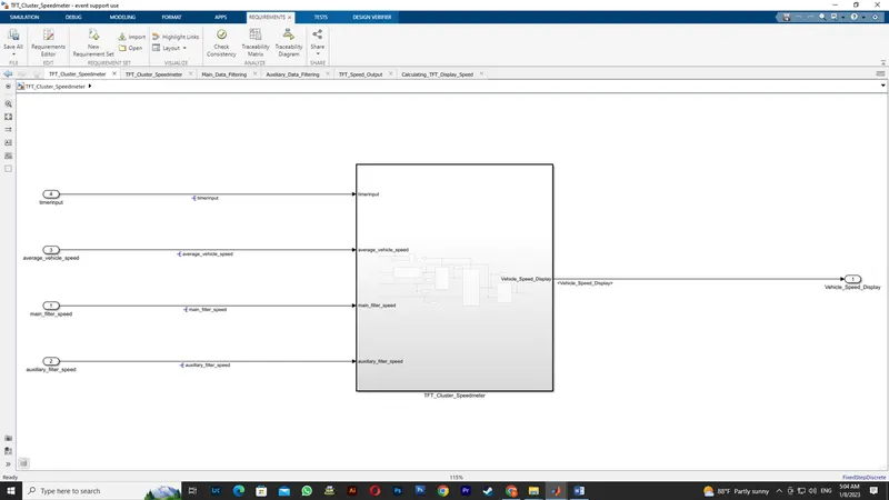
Inside TFT_Cluster_Speedmeter subsystem it consist of below Model.
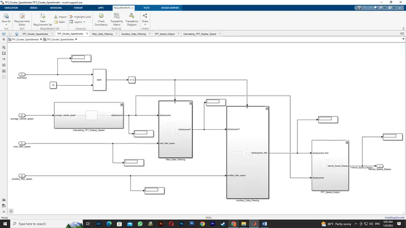
As per Requirements the subsystems are made which is as seen below.
Requirements:
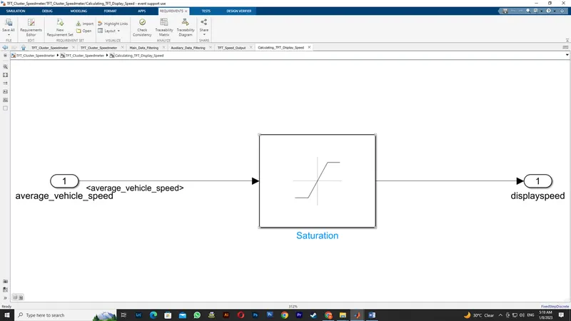
1.1 Calculating TFT Display Speed
|
Average Vehicle Speed would be displayed only if its between 2 kmph & 250 kmph. Any value outside this range will be discarded by its lower limit & upper limit |
|
When Average Vehicle Speed is < 2 kmph, DisplaySpeed = 2 kmph |
|
When Average Vehicle Speed is in between 2 kmph & 250 kmph, DisplaySpeed = Average Vehicle Speed |
|
When Average Vehicle Speed is > 250 kmph, DisplaySpeed = 250 kmph |
 1.2 Main Data Filtering
|
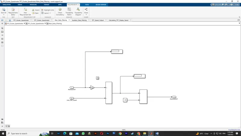
Main Data Filtering subsystem will be activated for every 10th millisecond |
|
DisplaySpeed1 (t) = ((DisplaySpeed (t) x 0.65)/ Main Filter Speed Value) 0.05 |
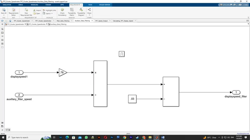
1.3 Auxiliary Data Filtering
|
Auxiliary Data Filtering subsystem will be activated for every 10th millisecond |
|
DisplaySpeed_Filter (t) = ((DisplaySpeed1 (t) x 0.78)/ Auxillary Filter Speed Value) - 0.03 |
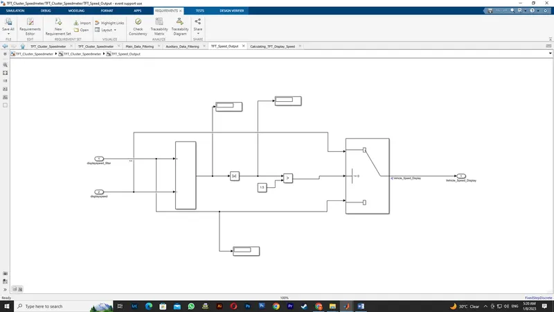
1.4 TFT Speed Output
|
If |(DisplaySpeedFilter - DisplaySpeed)| > 1.5 |
|
{ |
|
Vehicle Speed Display = DisplaySpeed |
|
} |
|
else |
|
{ |
|
Vehicle Speed Display = DisplaySpeed Filter |
|
} |
SLDD:
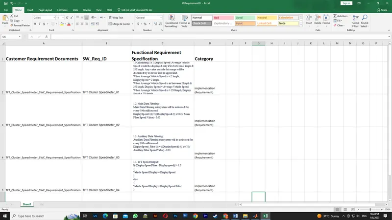
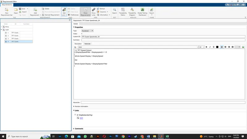
REQUIREMENT TAGGING REPORT:
Requirement tagging is done to the subsystem which is as seen below
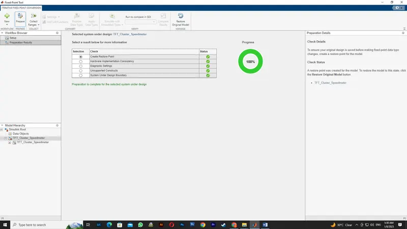
FIXED POINT TOOL:
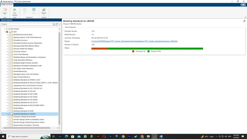
MODEL ADVISOR JMAAB COMPLAINCE TEST:
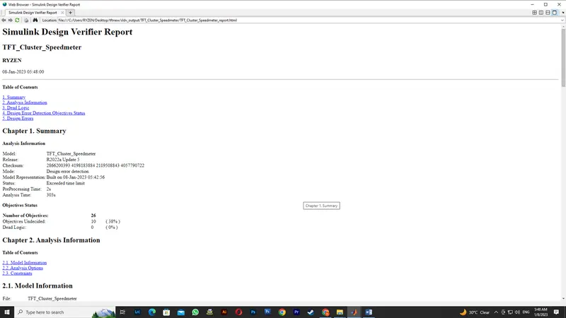
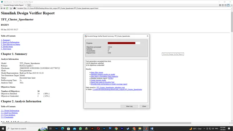
SLDV DESIGN ERROR DETECTION REPORT:
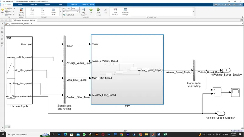
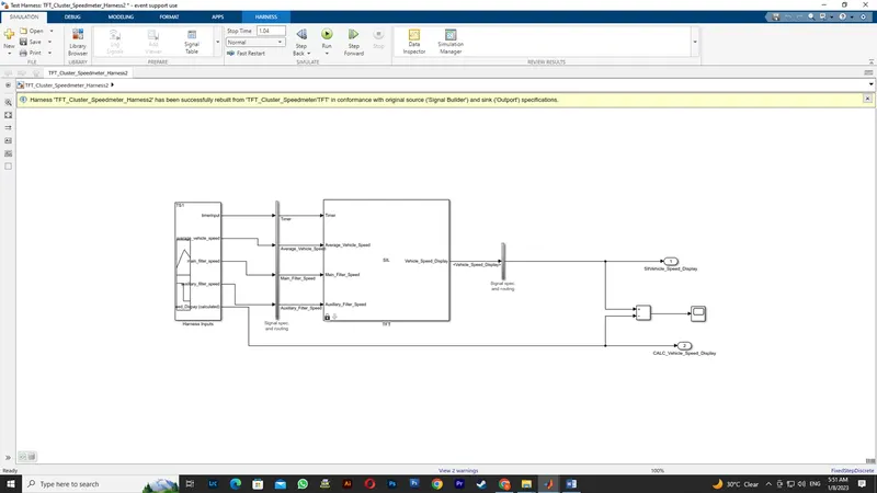
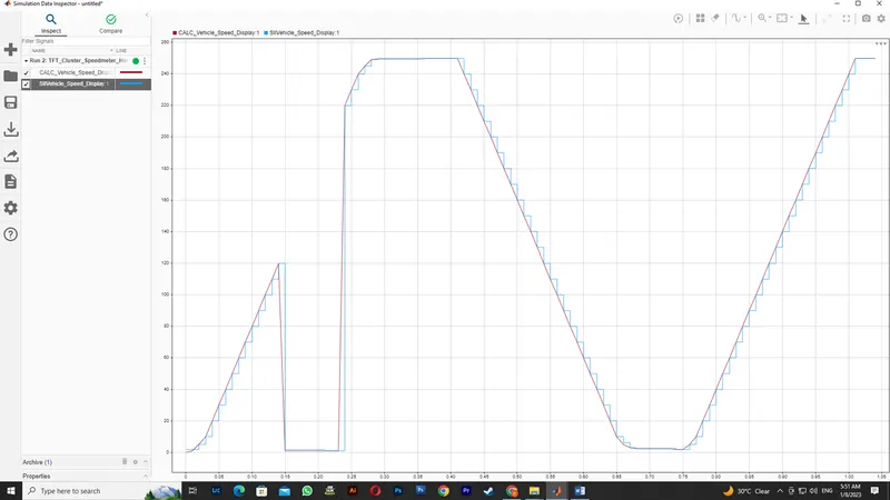
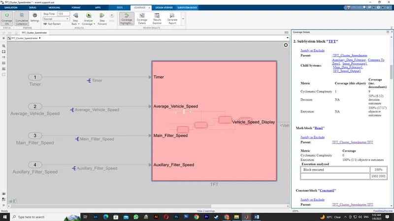
FUNCTIONAL TESTCASE ,MIL,SIL,COVERAGE ANALYSIS:
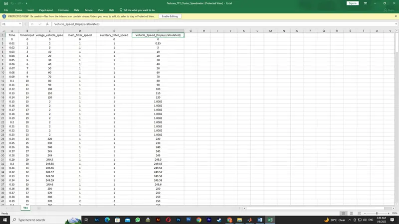
MIL
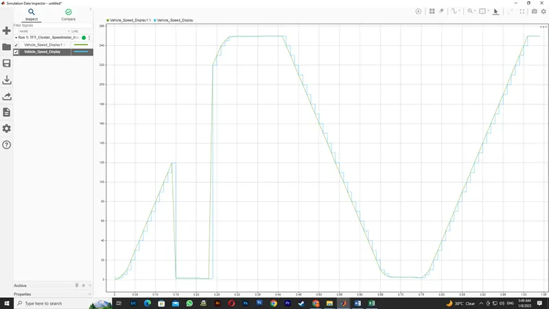
SIL
SLDV TEST GENERATION REPORT:
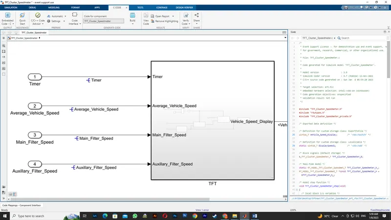
AUTOCODE GENERATION REPORT:
POLYSPACE ANALYSIS REPORT:
Steps to create a Polyspace Report:
- Initially, open the Polyspace in that new project click on start new project.
- The Project Properties dialogue box will open in that give the project name as we saved in the MATLAB,then select the location where it we need to save after that click Next or use the default location.
- Then ,it asks for the Projrct source,click on browserand select the folder where th .c file are generated then optionally we can add the include folder then clock on finish,the polyspace environment will open.
- In the configuraton settings option called Target & compiler select the source code language as c,change the target processor as X86_64.
- In the coding standards & code Metrics in that enable the check MISRA C:2004 also select the calculate the code metrics option
- After that go to bug finder analysis under that select the default one.
- Go to reporting enable the generate report option and ouput formet as PDF or any file we need
- Finally save the polyspace and run the Bug Finder.
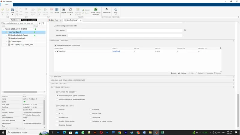
TEST MANAGER REPORTS:
RESULTS:
The simulink model is developed as per the requirement and sldd creation, JMAAB Testing, MIL and SIL Coverage report & Harness results for the model are done.