Project 2_Design & Analysis of a Hostel building at Guwahati, Assam
AIM
This project aims to model,analyse ,design and preparation of constructional drawings of a G+3 Hostel building located in Guwahati, Assam by provided seismic details of the location and type of building to be constructed using ETABS software. This project also aims the complete checks of the analysis results confirmed by various IS codes before preparation of final drawings by analysing multiple models of the same building. Another main goal of this project is to model, analyse, design and detailing of piles caps to transfer column load to pile foundation by using pile capacities and subsoil data obtained from soil reports by using SAFE software. Preparation of sectional details of RCC members and their reinforcement details of respective selected sections using AUTOCAD software is the final goal of this project.
MODELLING OD TRIAL FRAMING PLAN 1
Modelling started by selecting built in settings

<!--[endif]-->
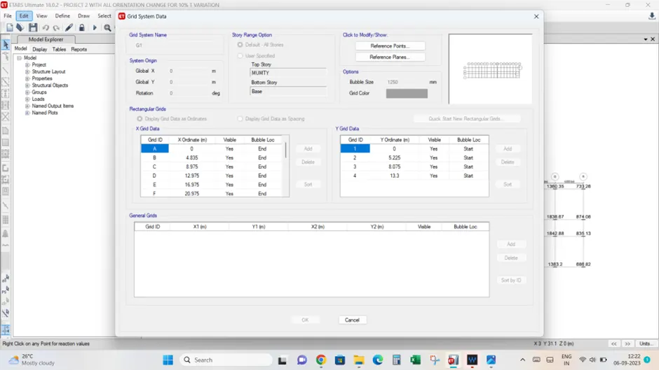
Model is created by providing corresponding grid data provided
<!--[endif]-->
Grid system completed
<!--[endif]-->
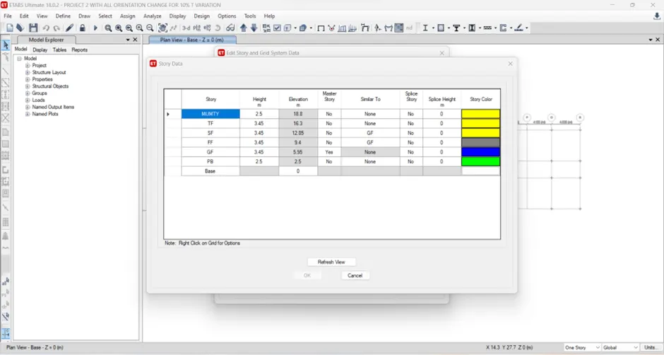
Story data of G+3 building along with mumty level for staircase roof and watertank provisions are also considered. Floor level of building lies at a height of 2.5m above foundation level inorder to control flood water into the building.
<!--[endif]-->
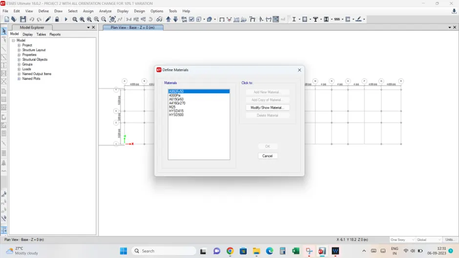
Material properties defined as M25 grade concrete and Fe500 steel for longitudinal and Fe 415 grade steel fo shear reinforcements
<!--[endif]-->
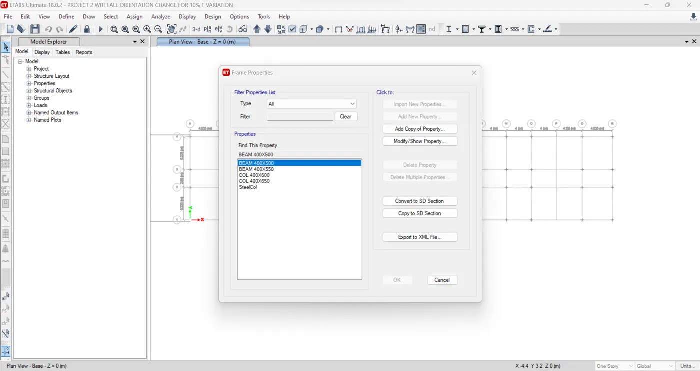
Frame section properties defined. Since analysis is a trial and error process, multiple section properties for columns and beams are defined. Appropriate effective moment of inertia (0.7I for columns and
0.35I for beams and torsion constant as 0.001 )are considered for seismic analysis in property modifiers.
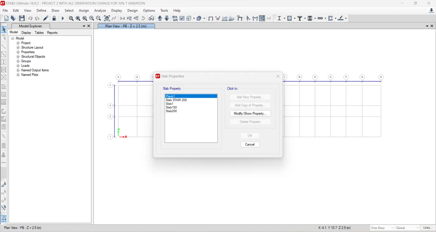
Slab section considered for different places (150 mm thick for common areas,200 mm thick for staicase slab and water tank slabs - slabs are modelled as 'membrane' elements)
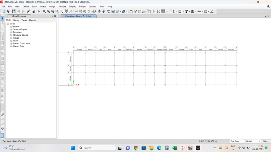
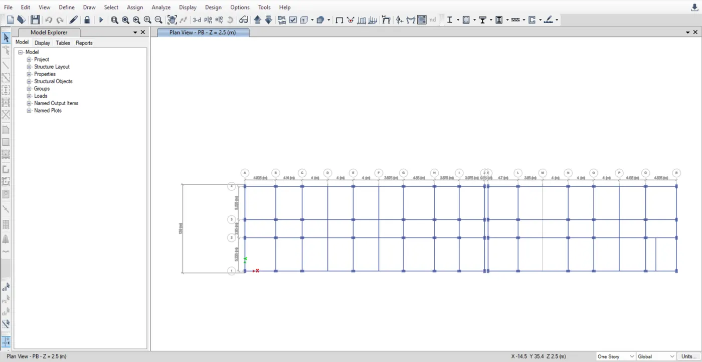
Trial 1 framing plan for Plinth beam level, typical intermediate story level and mumty level as shown below.
Column - 400 mm x 600 mm
Beams - 400 mm x 500 mm
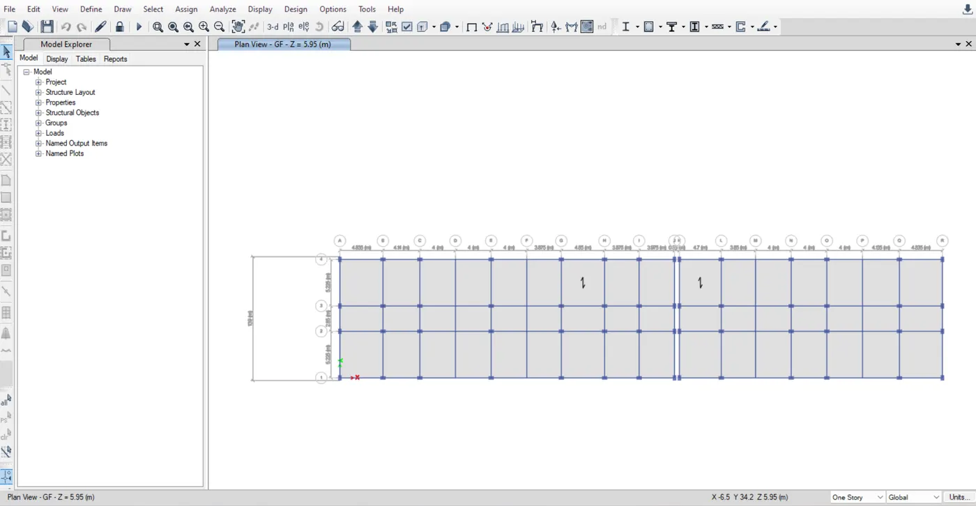
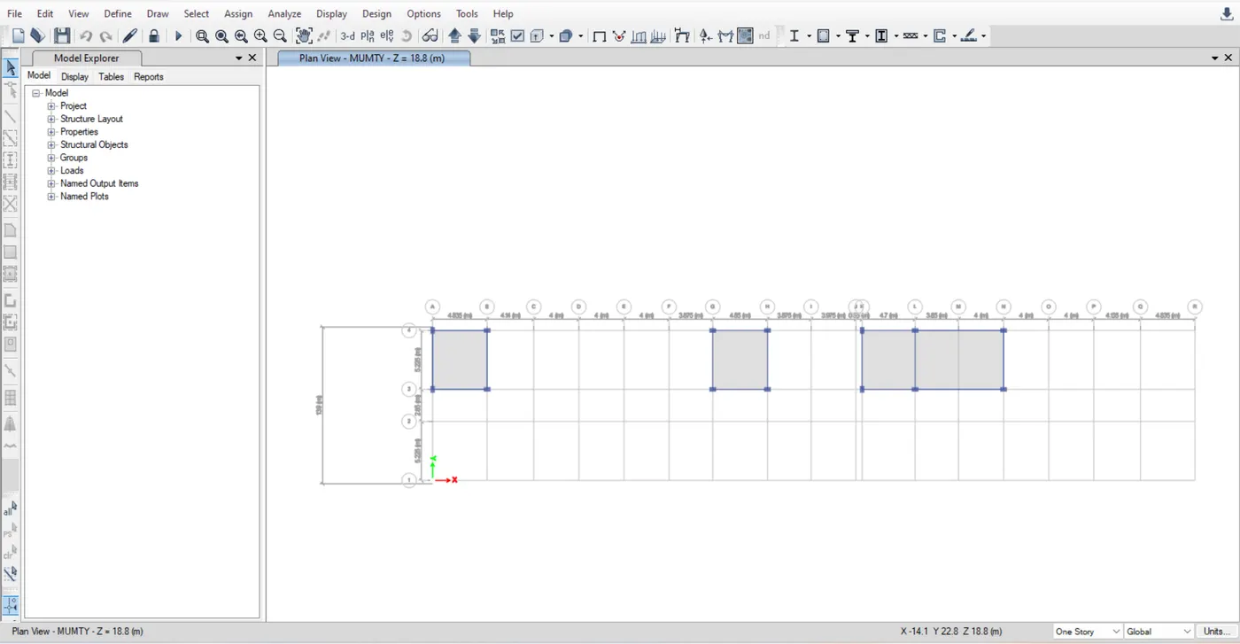
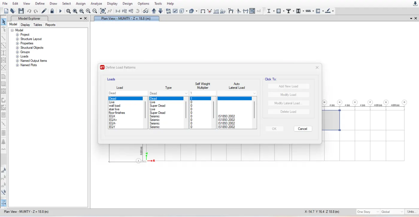
Load patterns are defined accordingly. Earthquake load patterns are also defined with permissible eccentricity. Seismic data provided as per location and importance of building provided in the project.
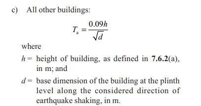
Time period is given as per IS 1893:2016 , Cl 7.6.2 case "c" for all other buildings
h=18.8m and d=67.8m Ta=0.206 sec
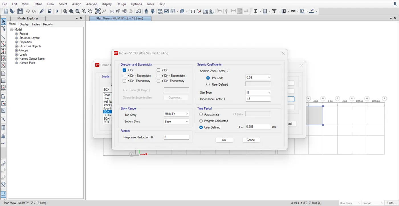
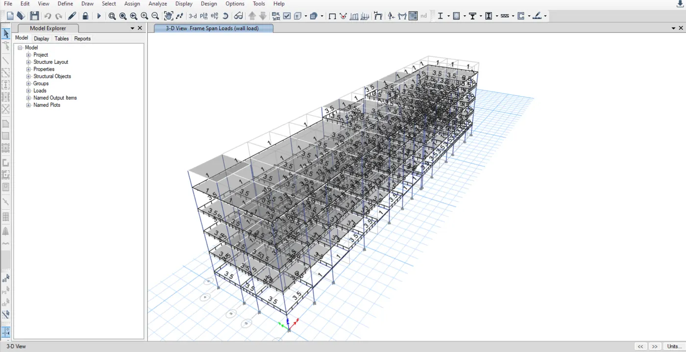
LOAD APPLICATION ON FRAMES
Wall live load = 3.5 kN/m
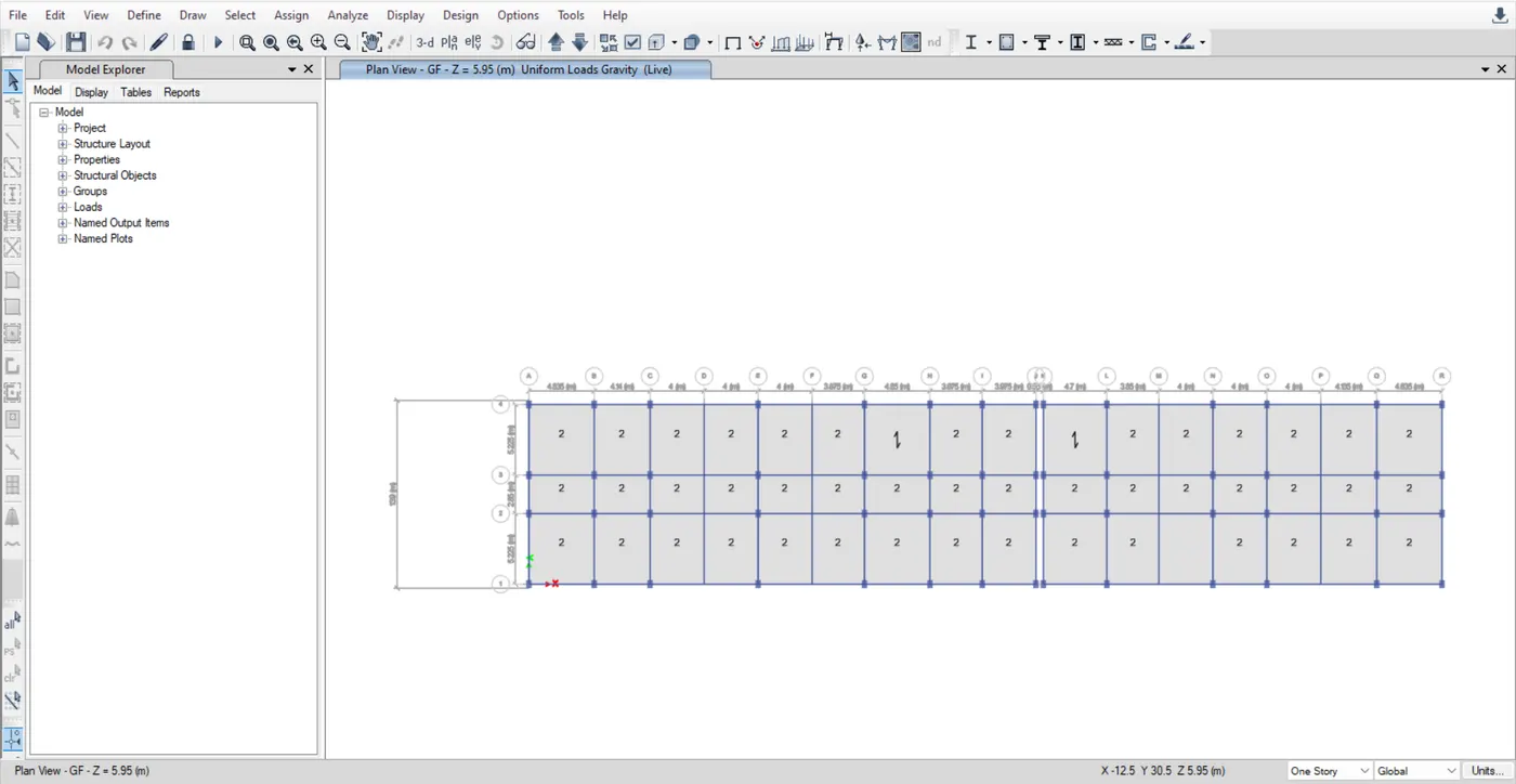
Live load on floors = 2kN/m2
Wall load on balconies = 1 kN/m
Floor finishes = 1 kN/m2
Roof live load = 1kN/m2
Stair live load = 3 kN/m2
Water tank load = 5 kN/m2 ( as per assumed capacity of 25000 L)
All these loads are applied as per specific load patterns corresponding to respective elements as per IS 875 part 2
Frame load
Typical floor live load
Mass source defined for seismic weight calculation. Live load is considered with a factor of 25% for up to and including load intensity of 3 kN/m2 as per IS 1893 Table 10
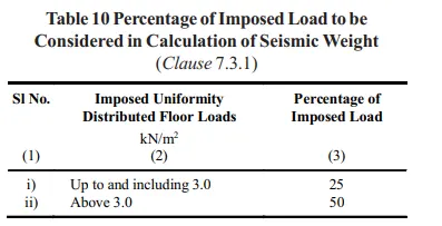
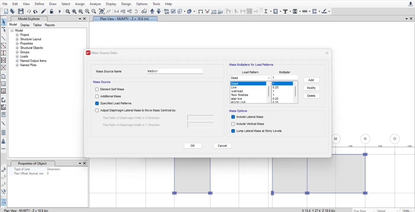
Since it is a G+3 Building live load reduction as per IS 875 part 2 Cl 3.2 is NOT CONSIDERED
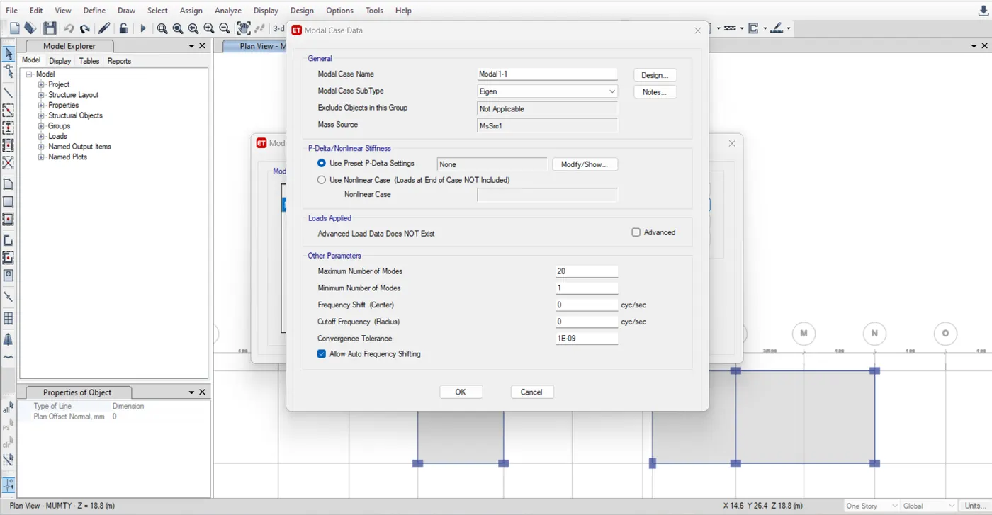
Modal case defined for modal response spectrum analysis with number of modes considered for initial analysis as 20
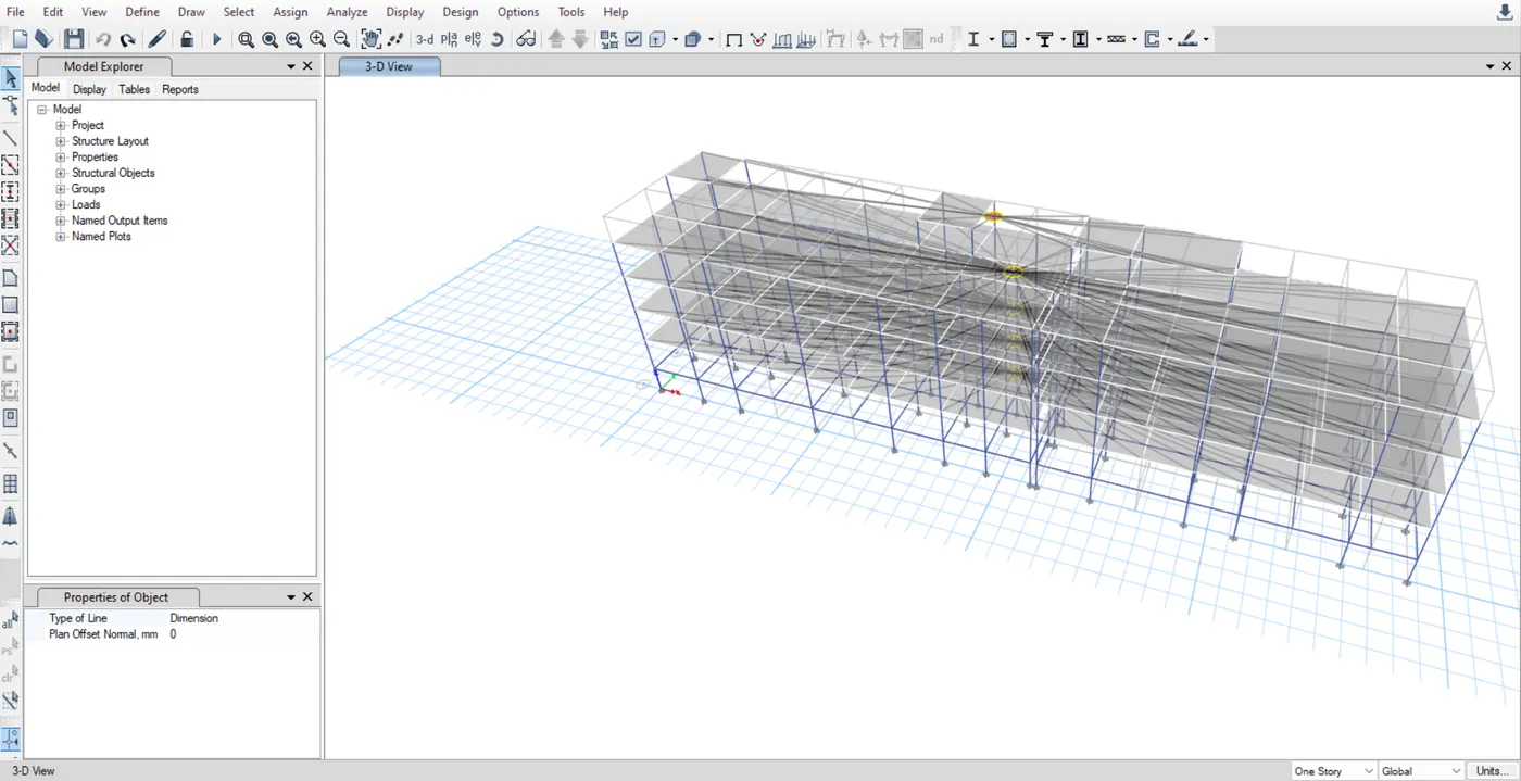
Diaphrams are assigned for each floor slabs for lateral load transfer.
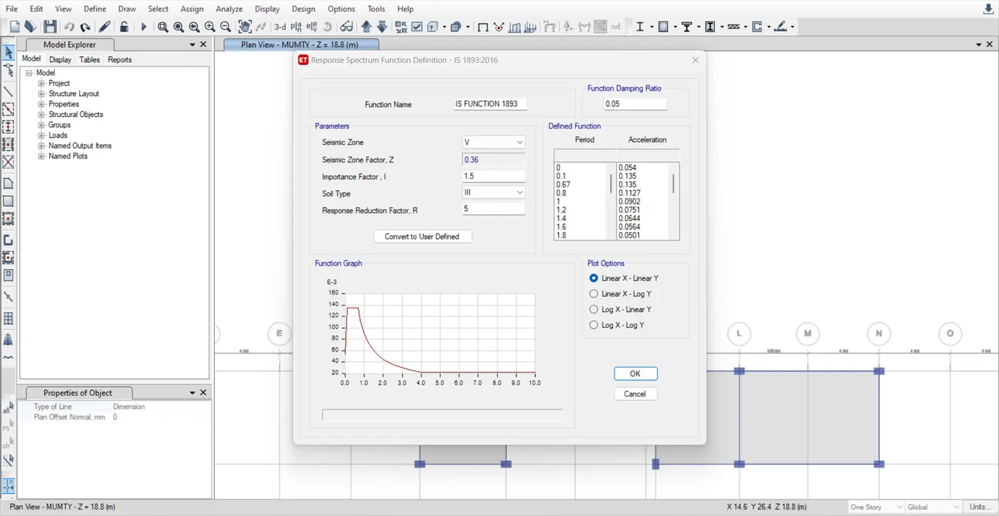
Defining response spectrum
New response spectrum function is defined based on IS 1893 and all the required data is submitted
Based on this data new response spectrum load cases also defined (RSX and RSY with generated scale factor)
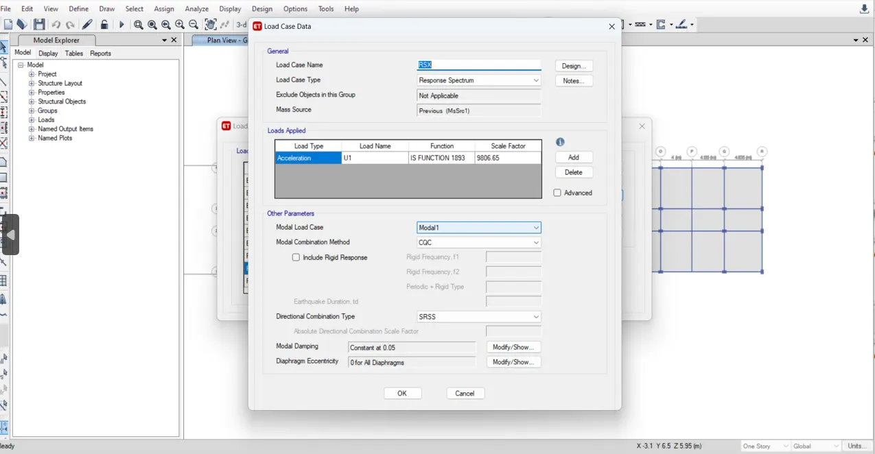
similarly defined for RSY with same scale factor
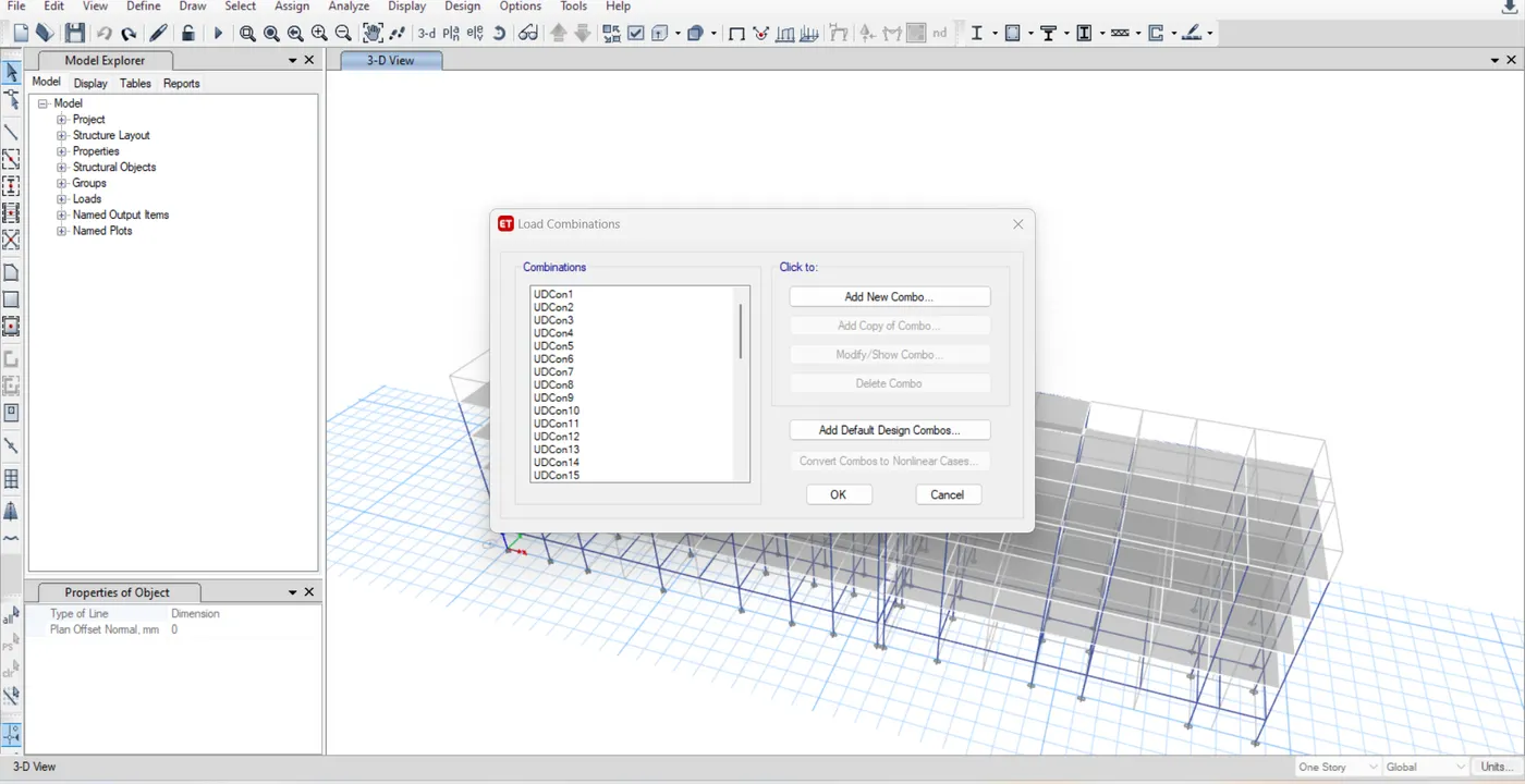
Defined load combinations as per system generated based on respective IS codes
ANALYSIS IS COMPLETED AND MODEL IS TAKEN FOR FURTHER CHECKS
SCALE FACTOR CORRECTION
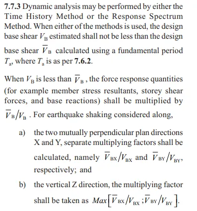
As per IS 1893 :2016 cl 7.7.3
 F
F
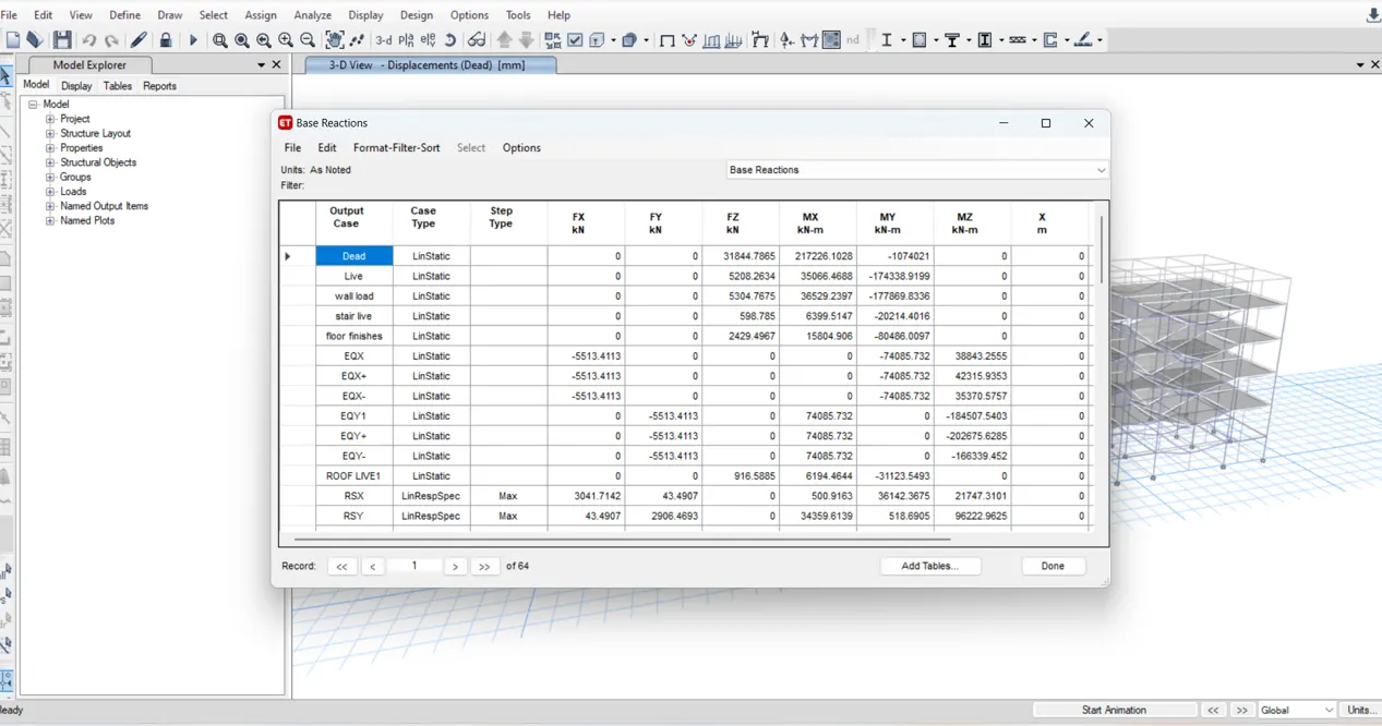
From the analysis
EQX = 5513.41 kN
EQY =5513.41 kN
RSX = 3041.71 kN
RSY = 2906.49 kN
as per given clause of IS 1893:2016
Response spectrum scale factor should be multiplied with a factor (VB'/VB) to satisfy the codal provisions
VBx'/VBx = 5513.41/3041.17 = 1.81
VBy'/VBy = 5513.41/2906.49 = 1.9
Multiplied the scale factor genered initially (9806.65) with thses factor to obtain story response and base shear etc. calculation we get as
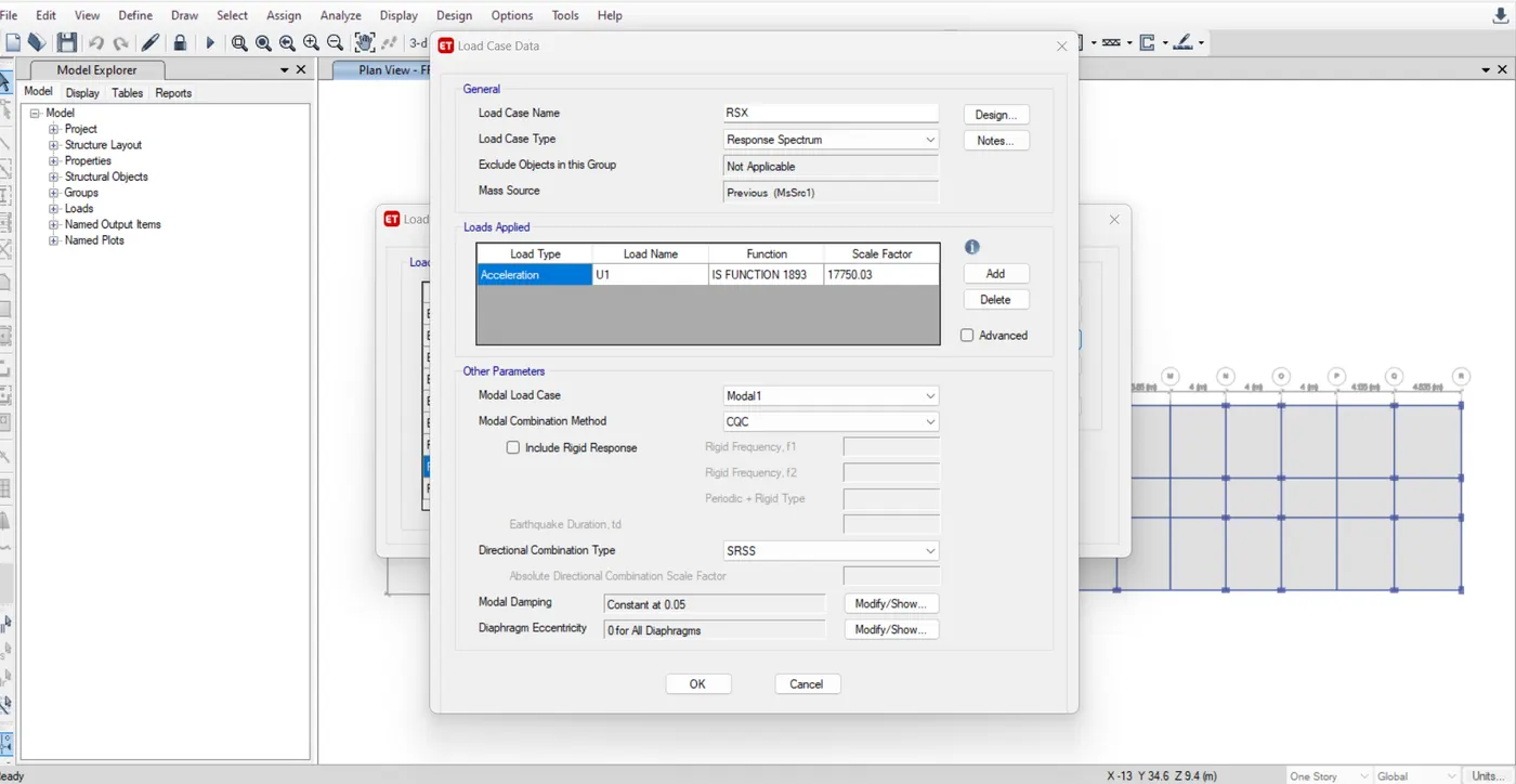
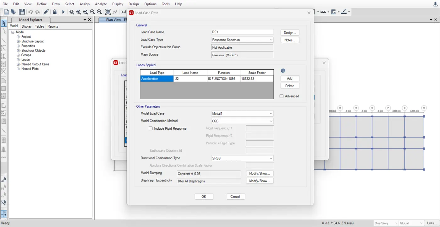
Run the analysis again and check the base reaction. We can see that Response spectrum base reaction became almost equal to the base reaction obtained from equivalent lateral force analysis
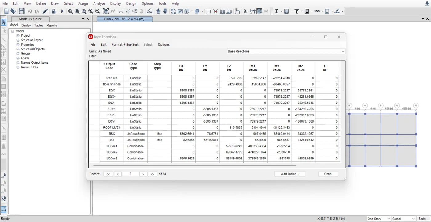
Now we can save the file and open new one with only response spectrum load cases. Earthquake load cases ran only to get the corrected scale factor.
NOM FOLLOWING IMPORTANT CHECKS SHOULD BE PERFORMED
- CHECK FOR VERTICAL IRREGULARITY BY ANALYSING MODAL MASS PARTICIPATING RATIOS
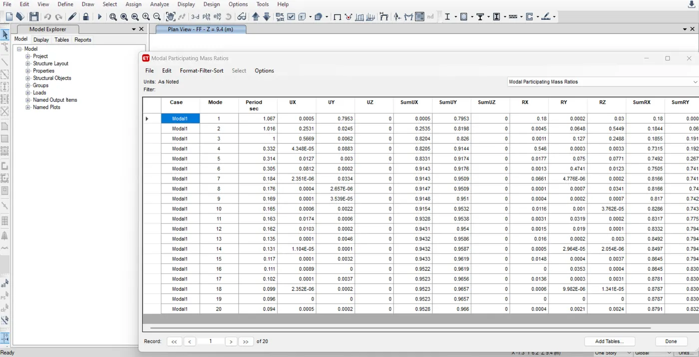
From the analysis result it is clear that eventhough forst mode is translational but second mode is dominated by torsion which is not satisfactory under seismic load conditions. From trial 1 frame analysis we can conclude that the framing plan is torsionally sensitive and unsafe under earthquake actions. Framing plan must be revised.
From the result it is evident that we need to improve the stiffness of the structure in X direction. Since we dont use any shear walls in the framing plan we can check the lateral stability of the structure by changing the orientation of the columns situated in the periphery.
FRAMING PLAN 2 WITH CHAGED ORIENTATION OF THE COLUMNS IN THE PERIPHERY OF THE BUILDING
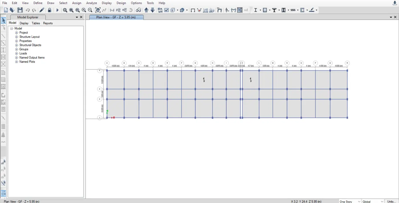
All the other things remined the same and analysis was done again and checked the modal mass participating ratios
- CHECK FOR VERTICAL IRREGULARITY BY ANALYSING MODAL MASS PARTICIPATING RATIOS
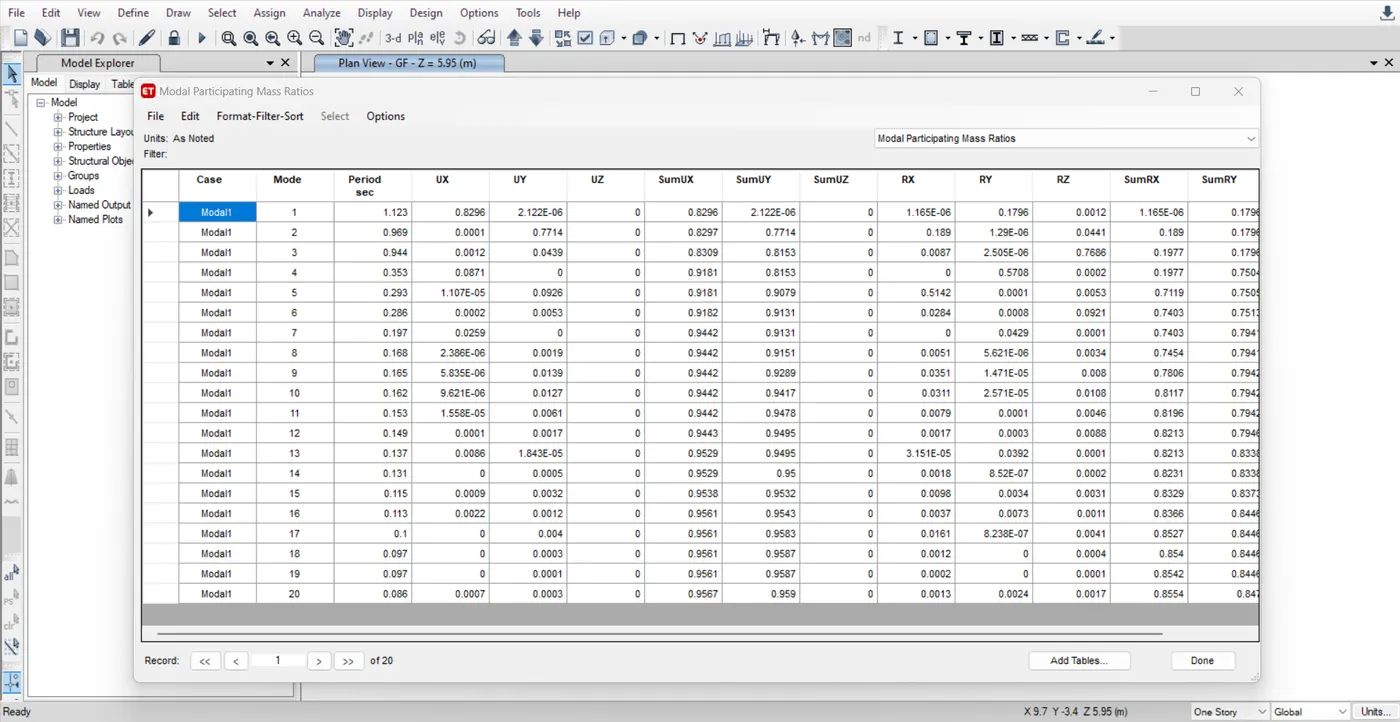
Now it is ok . The first two fundamental modes constituting translational and third mode falls to rotation.
2. CHECK FOR IRREGULAR MODES OF OSCILLATION IN TWO PRINCIPAL PLAN DIMENSIONS AS PER TABLE 6 , IS 1893:2016
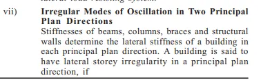
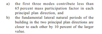
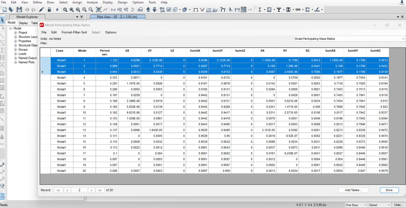
As we can see the first three modes contributing more than 65% mass participation in all the mutually perpendicular direction . HENCE OK
Also time period corresponding to Mode 1 and Mode 2 are 1.123 sec and 0.969 sec respectively. Clearly variation is larger than 10% of the larger value . HENCE OK
3. NUMBER OF MODES CONSIDERED AS PER CL 7.7.5.2 IS 1893 :2016
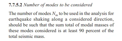
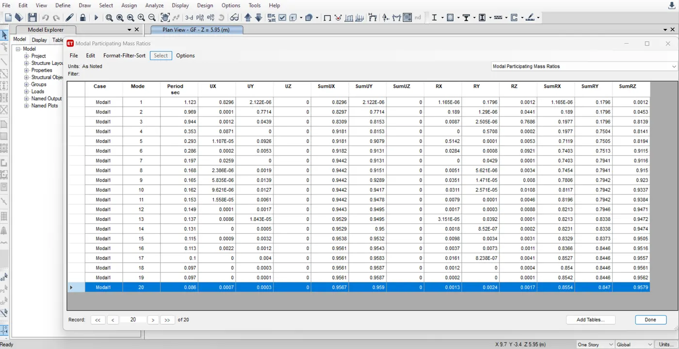
Number of modes considered is 20. It is clear from the data is tha 20 modes contributes more than 90% of total seismic mass. HENCE OK.
4. CHECK FOR AXIAL LOAD RATIO OF COLUMNS TO FIX ITS DIMENSION.
Axial load ratio of the columns should be less than 0.4 fck
Here all the columns having the same size (400x600). lets take a column with maximum reaction expected under a load combination of 1.5(DL +LL) and checking the axial load ratio is within the limit. By considering the column with largest reation this criterial will be satisfied by all the columns.
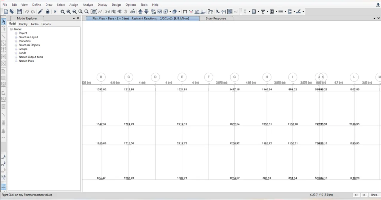
Consider the column in Grid 3-E with maximum reaction of 2219 kN.
Axial load ratio = Reaction load/Cross sectional area(fck)= 2219000/(400x600)25 = 0.37 which is less than 0.4 . HENCE OK
5. CHECK FOR TENSION IN COLUMN BASE
Tension may generate on column under lowest gravity load combination. Checking the reactions of column for the load combination with 0.9 load factor (for gravity loads)
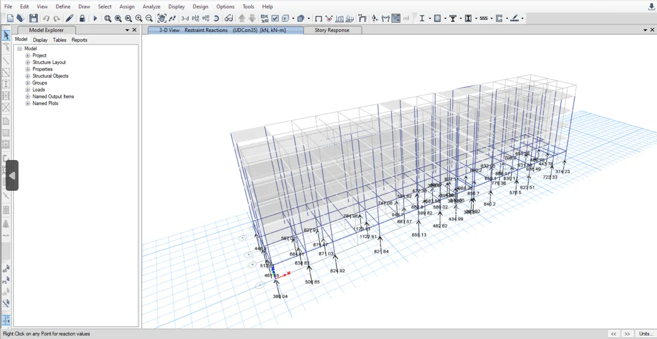
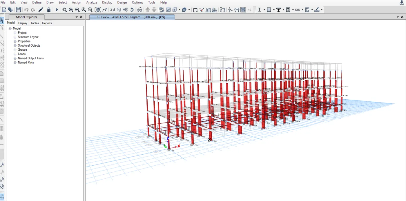
From the analysis results no column is under tension obtained .HENCE OK
6. CHECK FOR MAXIMUM STORY DRIFT
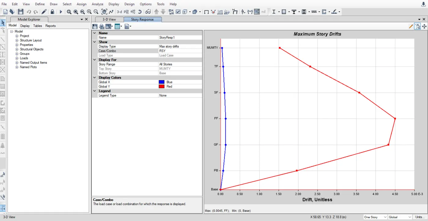
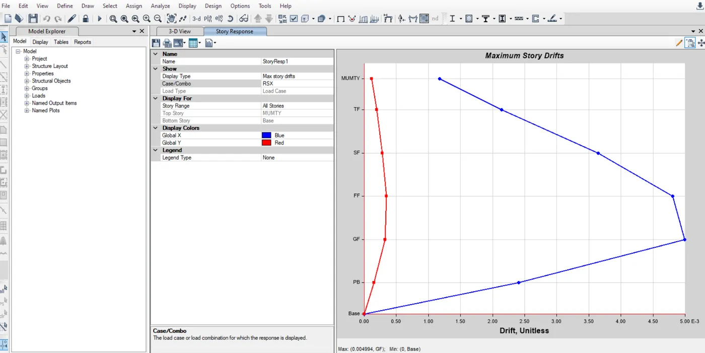
Maximum story drift should be less than 0.004 . Here in both response spectrum load cases it comes around 0.004 . HENCE OK
Now we can proceed for detailed design of the structure.
All members passed the design check
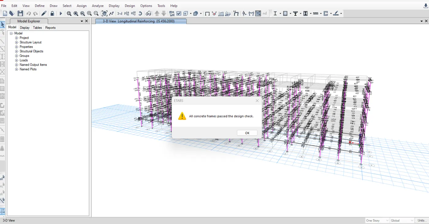
Column reinforcement data
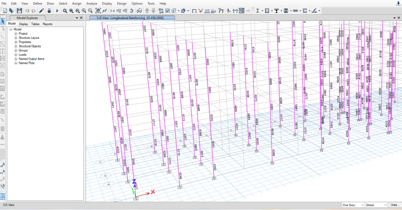
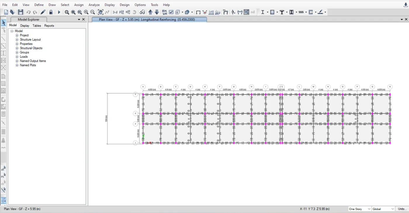
Typical Beam longitudinal reimforcement data
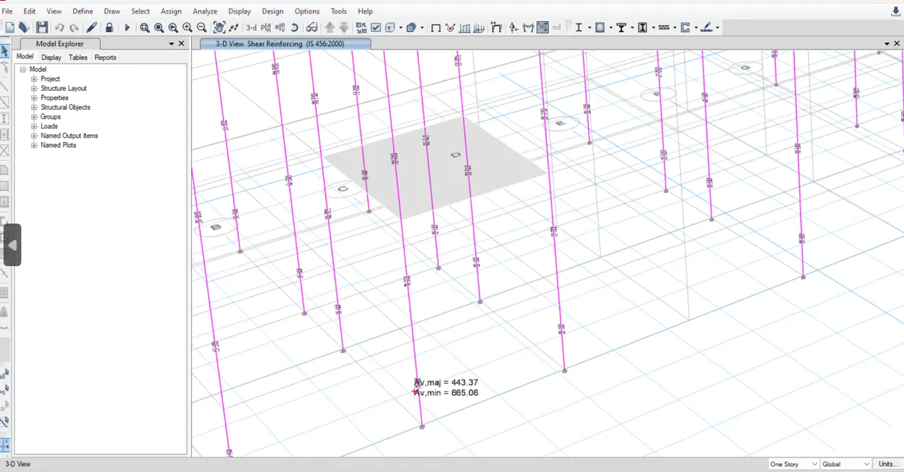
Shear reinforcement data for beams and columns
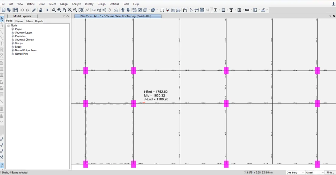
DEATAILING OF ALL STRUCTURAL MEMBERS CAN BE DONE AND THE MODEL CAN BE SEND TO SAFE SOFTWARE FOR PILE CAP DESIGN
Data available for SAFE input
Building rests on Type 3 Soil
Length of pile = 10m
Dia of Pile = 500mm
Pile capacity of single pile = 280 kN
Grade of concrete = 25 MPa
Grade of steel = Fe 500 and Fe 415
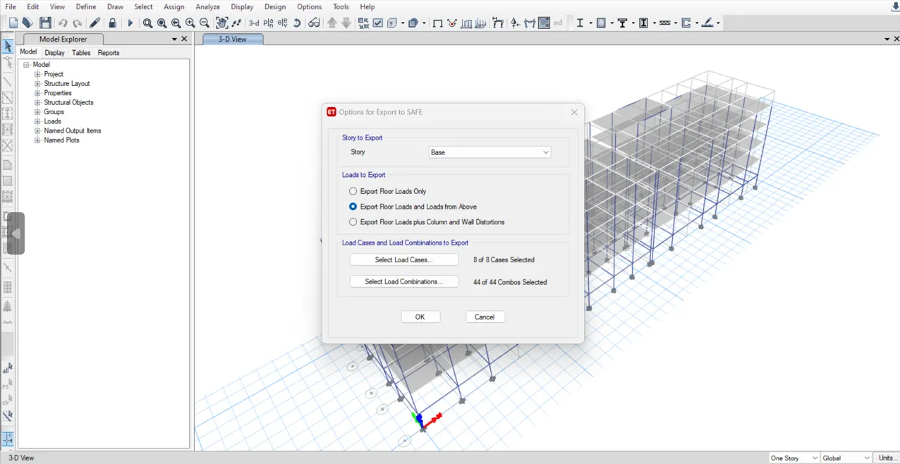
Exporting ETABS outputs for design of pile caps to SAFE software 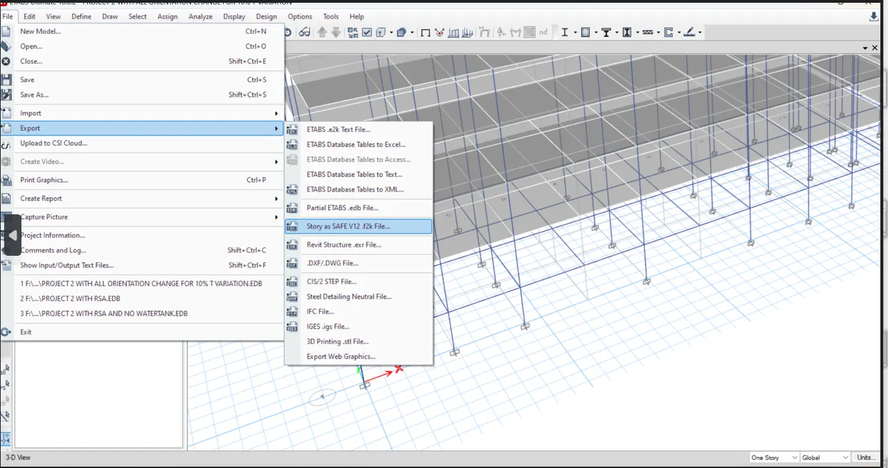
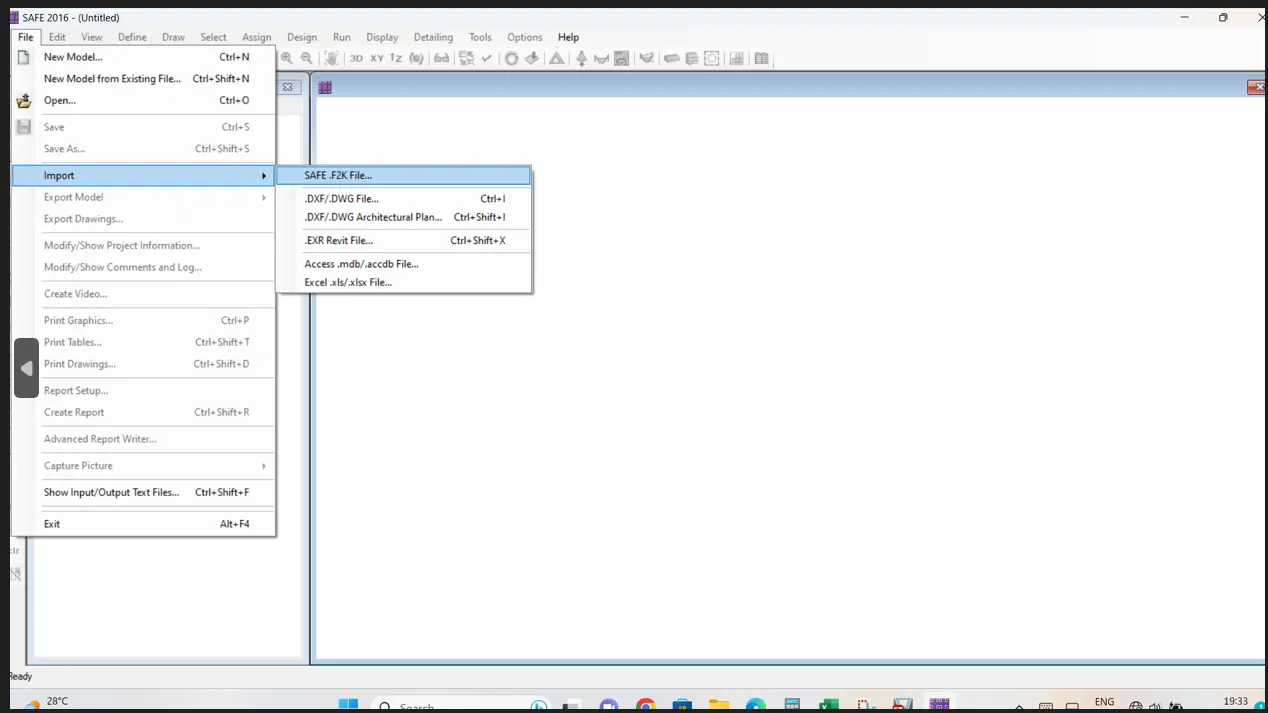
Importing data in SAFE
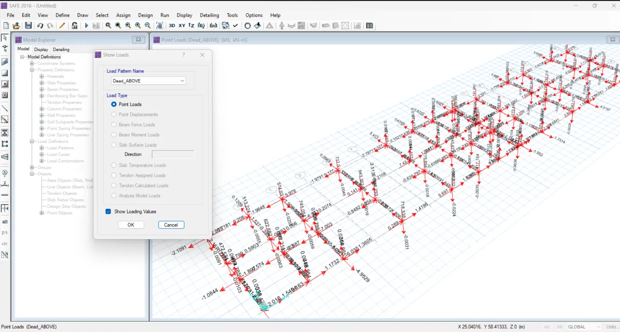
Cheked whether all loads are present at base level or not.
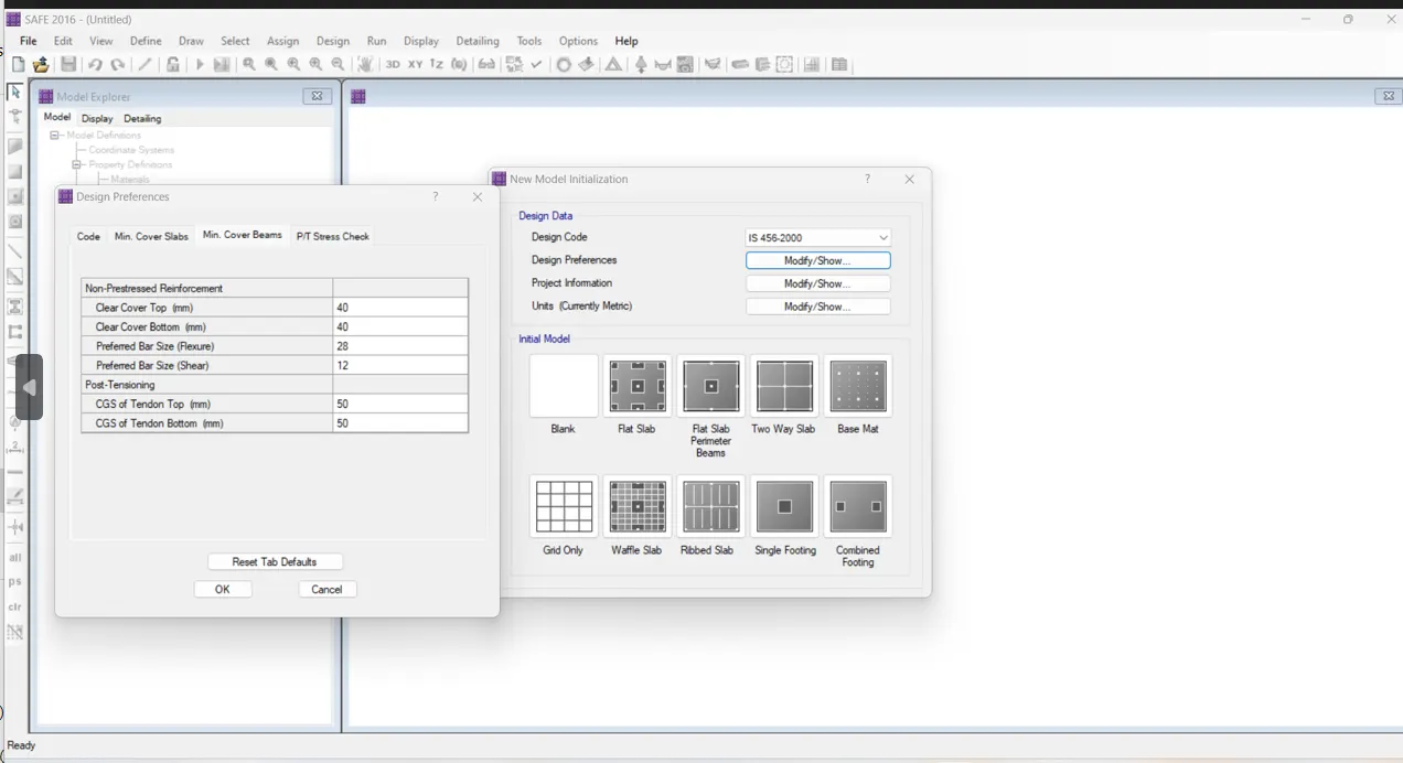
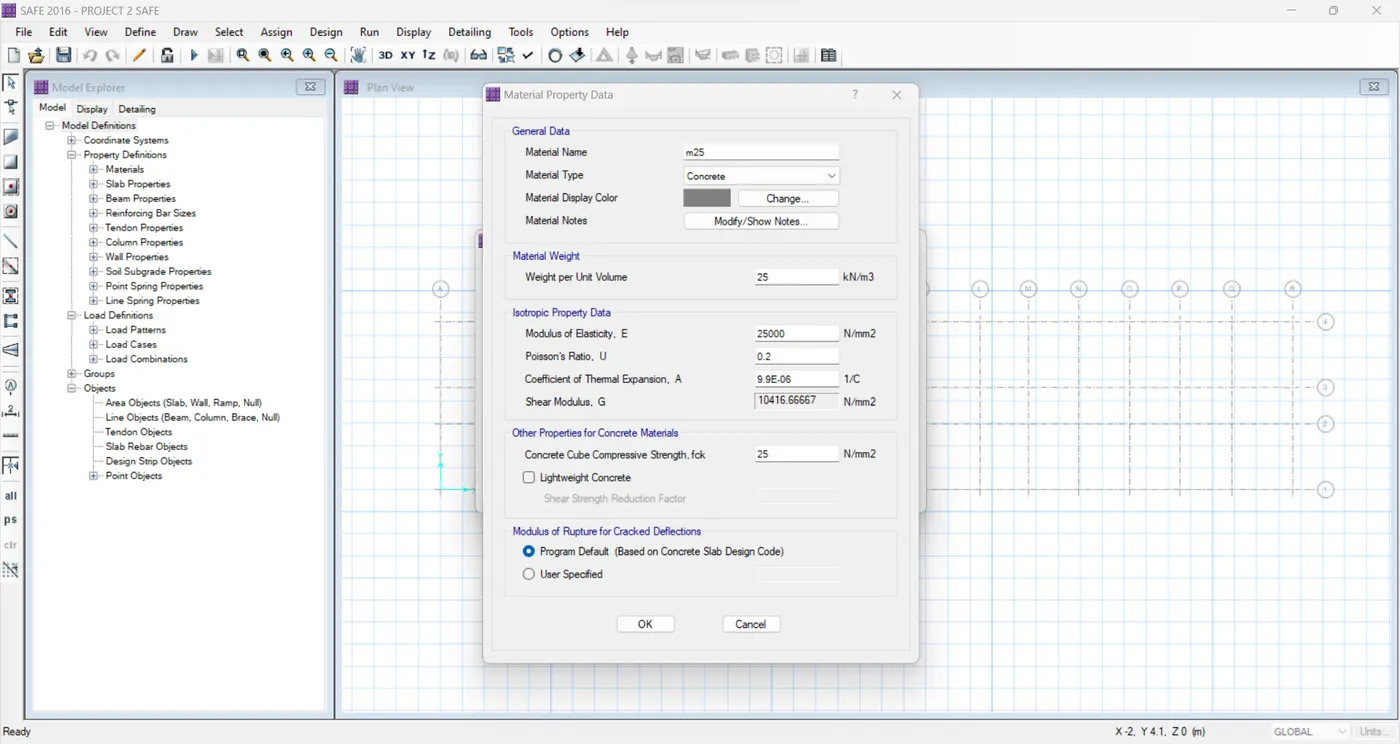
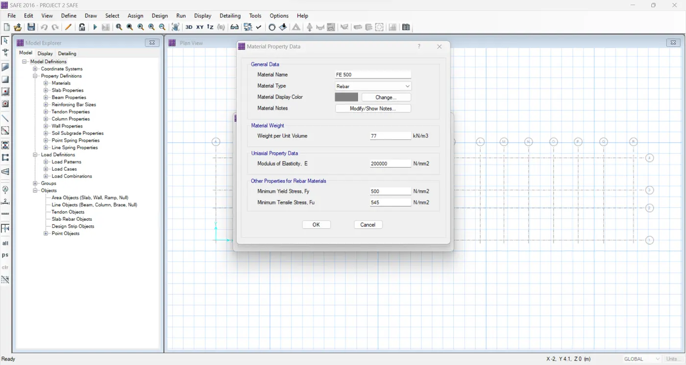
Defined Codes, Design preferences and Materials M25 concrete and Fe 500 steel
We have to define 3 slab properties for Pile cap design they are pile, pile cap and column. Pile and pile cap are defined as 'Mat' and column as 'stiff' elements. Intially all are given with a thickness of 800mm
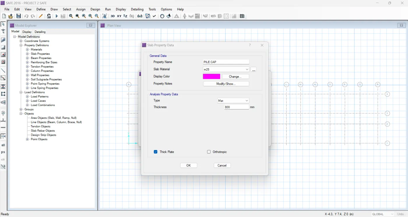
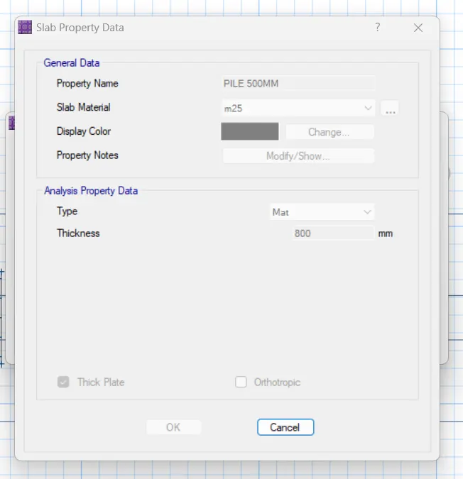
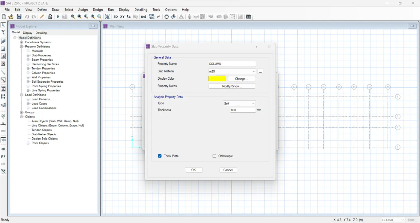
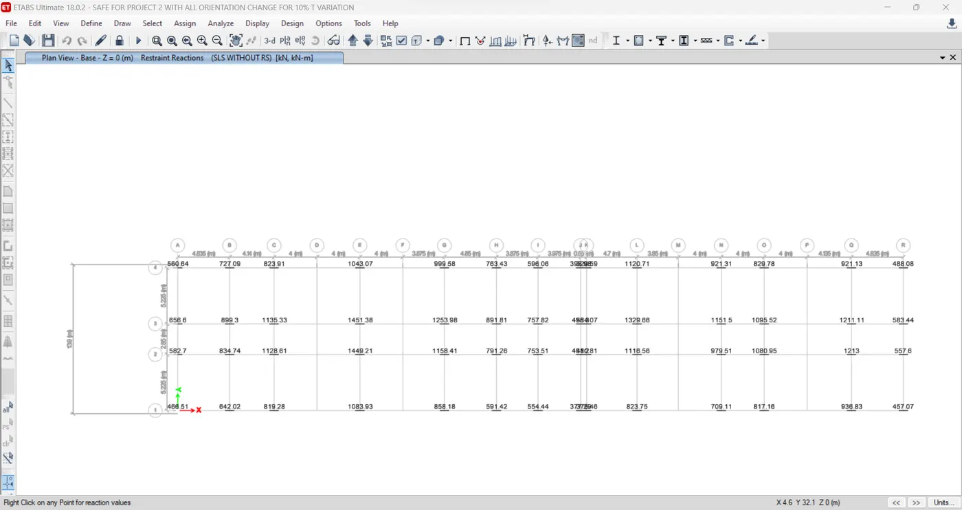
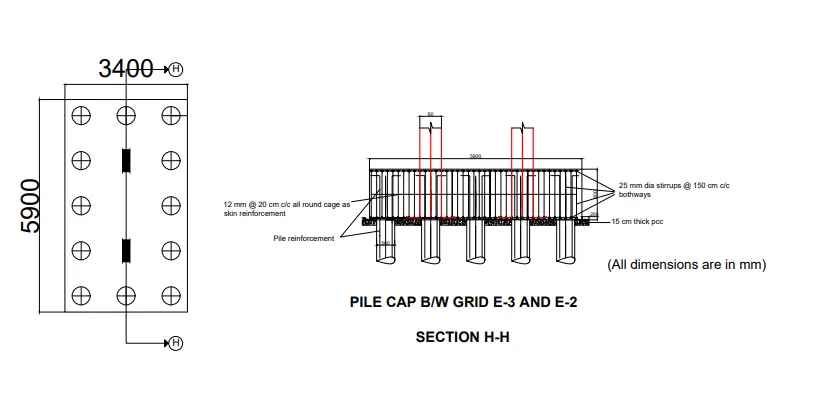
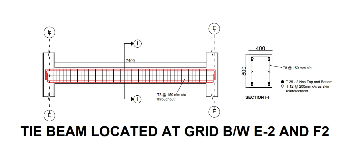
From the reactions with service load combinations from the ETABS and pile capacity obtained from soil report pile cap layout and tie beam lay out has been modelled. Tie beams are used to prevent the differential settlement of individual pile caps. Depth of tie beams are selected as the same depth of pile caps. Initial pile and pile cap specifications are taken as per IS 2911 Design and construction of pile foundation. C/ Distance between piles are taken as 2.5 times dia of pile. For the design Pile cap in the Grid E-3 and E-2. Size of pile cap is 3400mm x 5900mm. Depth is 800mm.
Service load reaction from ETABS output
Pile, pile cap and tie beam layout form SAFE
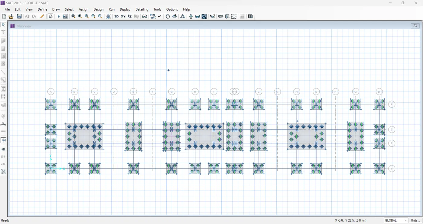
Reactions are also present 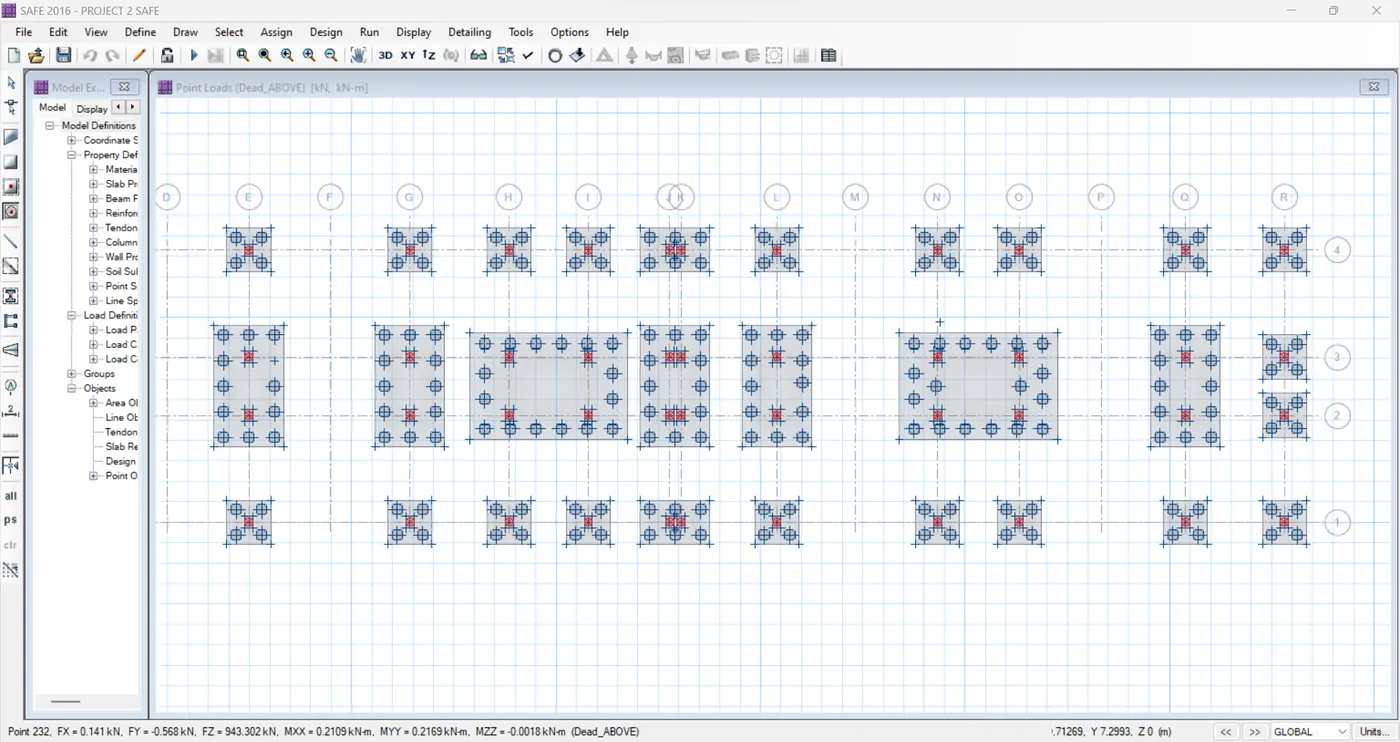
We assume the piles caps are rests directly on piles. Load trasfer to soil is generally negleted. We assume the piles as Pile springs with specific stiffness. We have to provide value of stiffness depend on modulus of elasticity of conctere, area of pile cross section and inversly proportional to length of pile.
K = EA/L
= 5000sqrt(fck) x (0.786 x 500x500)/10000
= 491.25 kN/mm
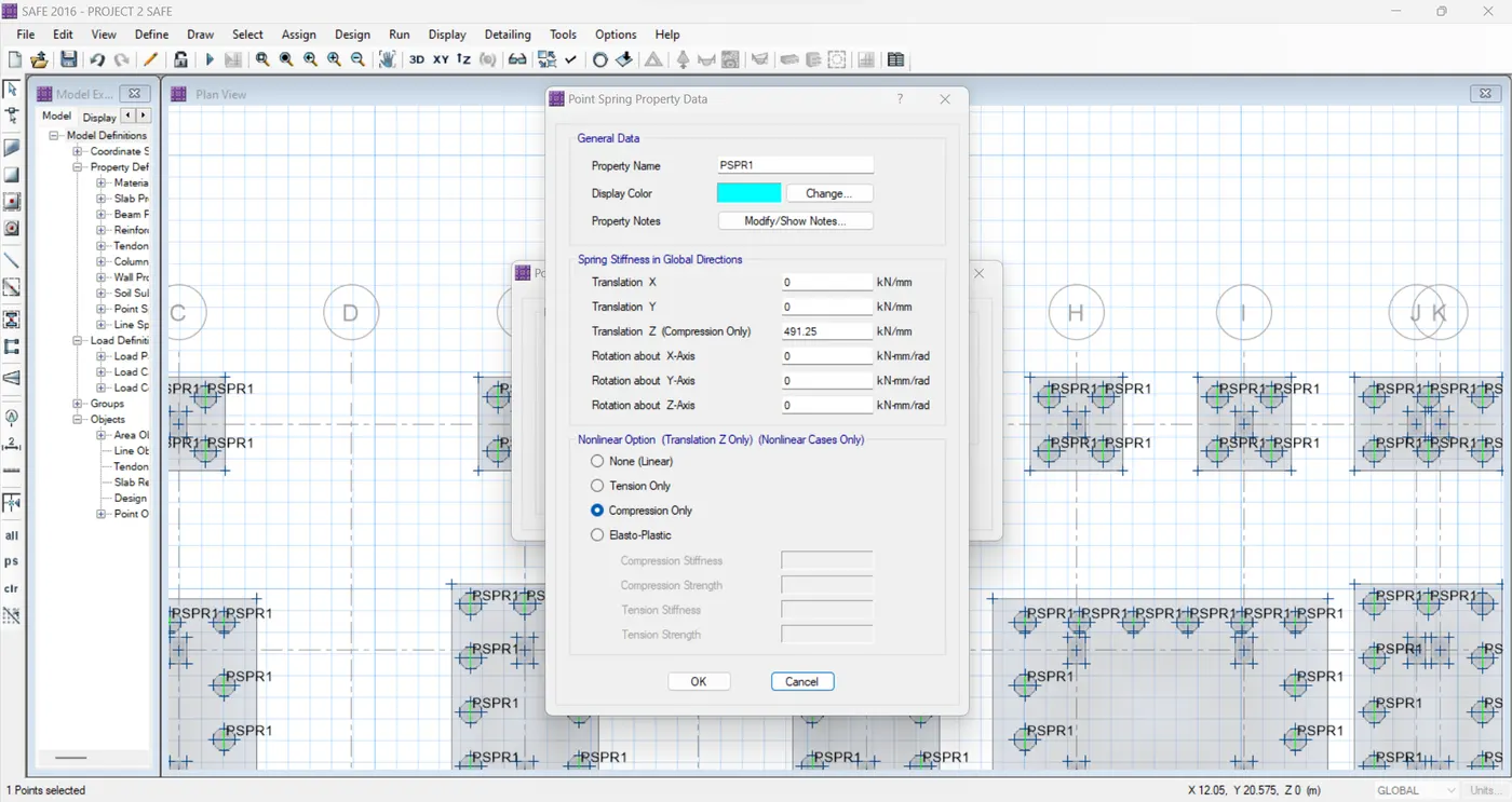
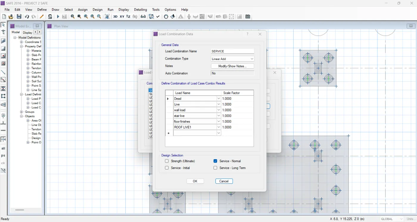
Service load combinations for settlement, bearing pressure, and punching shear check and Ultimate load combinations for steel calculation is defined
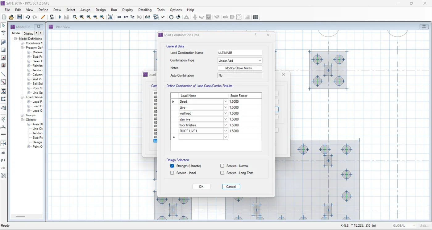
Analysis completed
1. Checking the deflection
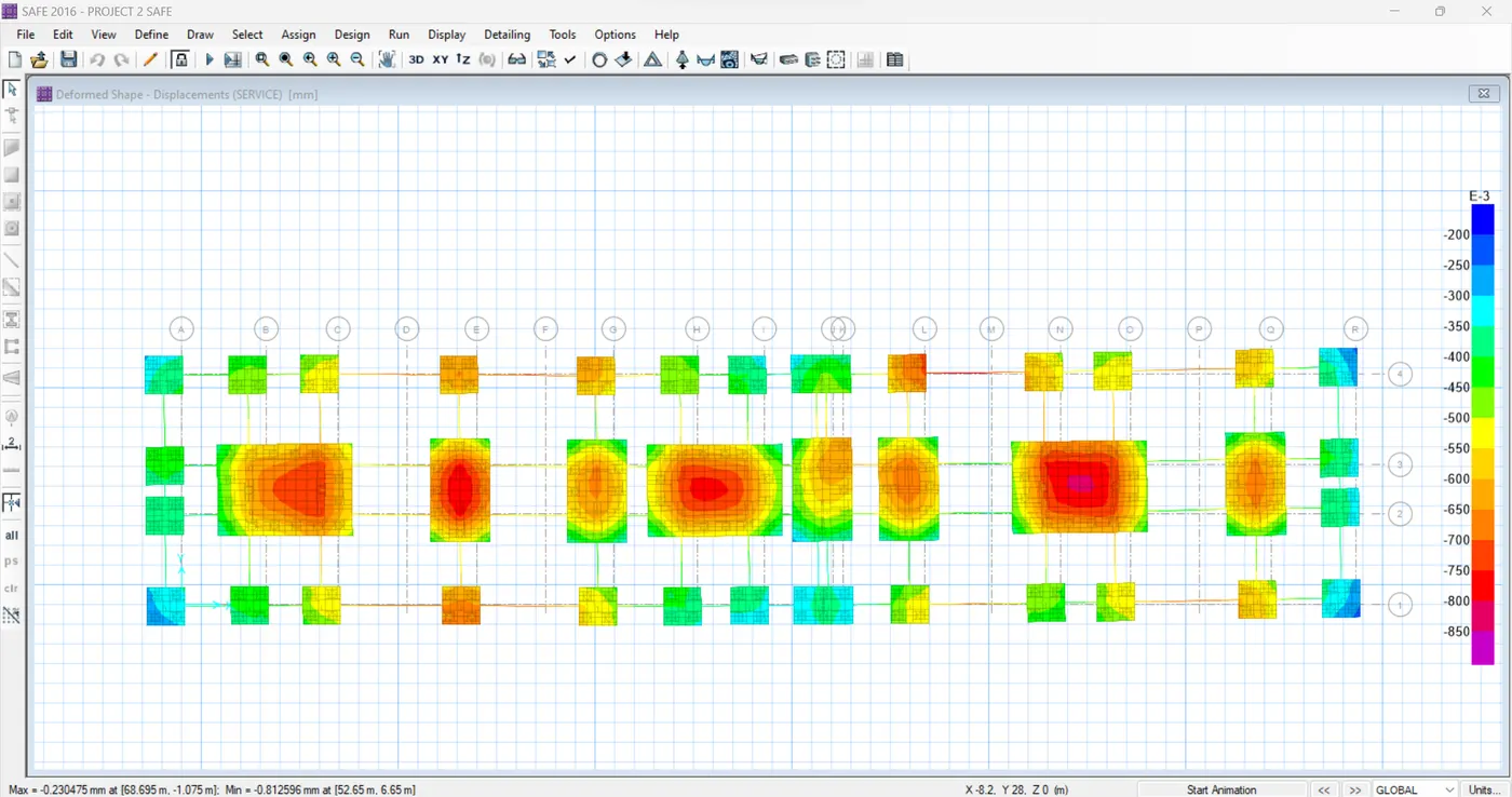
Maximum deflection is around 0.25 mm . Which is less and and satisfied for deflection criteria
2. Check for bearing pressure
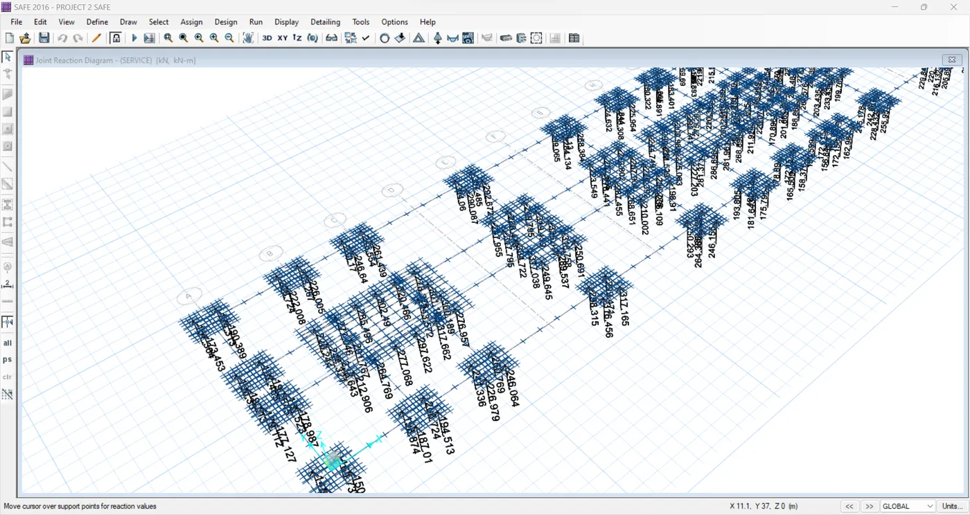
Almost all the value is below and near to 280kN which is the pile capacity. So bearing capacity criteria is also satisfied
3. Check for punching shear
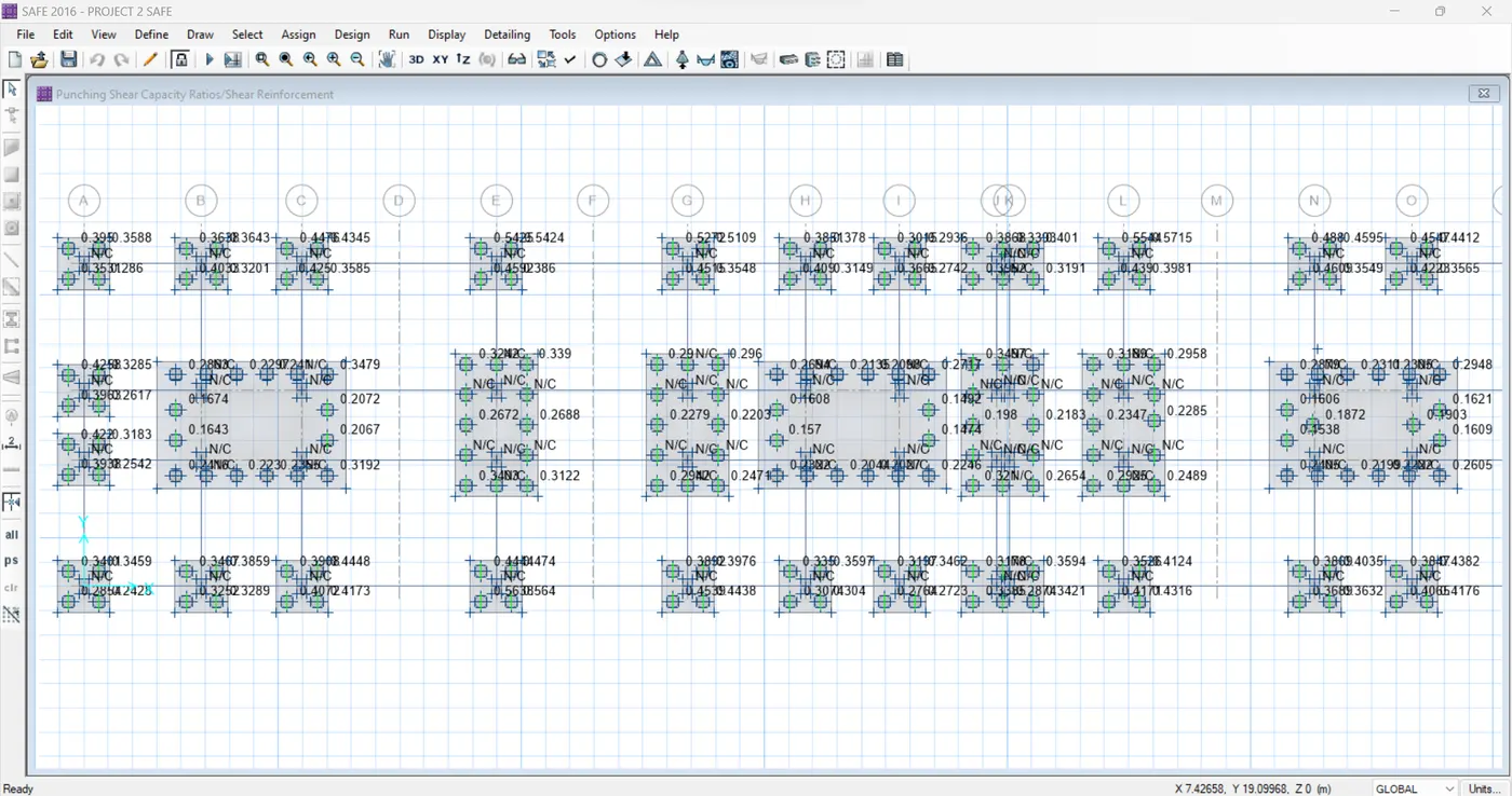
All the value is way below 1. Which is OK.For columns they are joined by tie beams so no punching shear is calculated (N/C) by the software. Which is also ok
Design of Pile cap and tie beams
For the design Pile cap in the Grid E-3 and E-2. Size of pile cap is 3400mm x 5900mm. Depth is 800mm.
For design of pile caps we need to draw design strips in both directions.
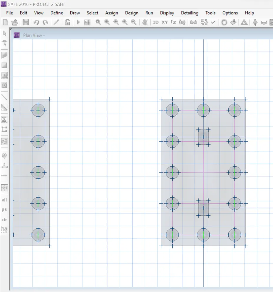
Strip based design values are obtained
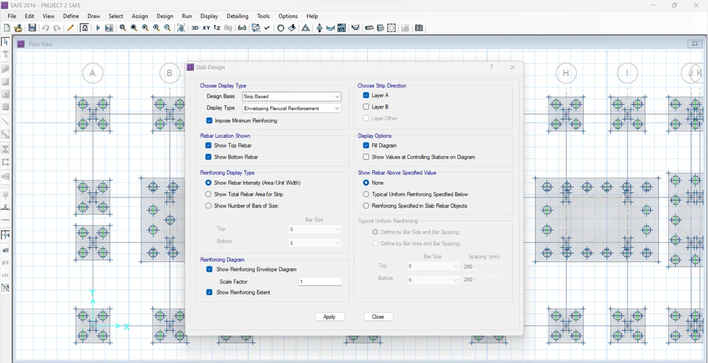
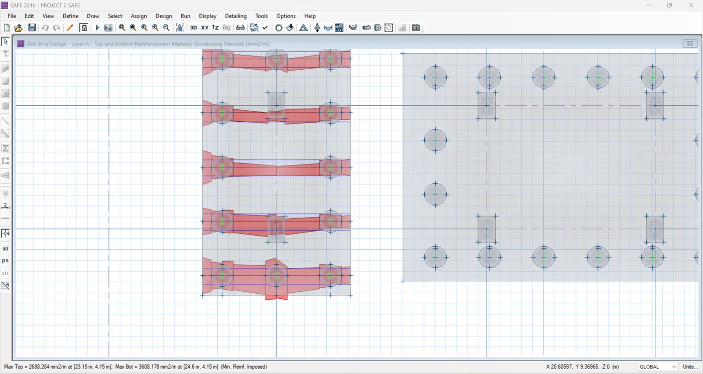
Max steel at bottom is obtained as around 3400 mm2/m in both layers which is almost equal to 25 mm @ 150 mm c/c. Conisering the easiness and to avoid confusions at construction stage uniform spacing od reinforements are provided throughout. We provide steel as stirrups allround and form a cage. We have to provide nominal amount of steel as Skin reinforcement. Provide it as 12 mm @ 20 cm c/c. Pile reinforements and column reinforcements are anchored at pile caps firmly.
ANALYSIS AND DESIGN ARE COMPLETED. FOLLOWING REINFORCEMENT AND RCC SECTIONAL DETAILS CAN BE SEND TO COSTRUCTION SITE.
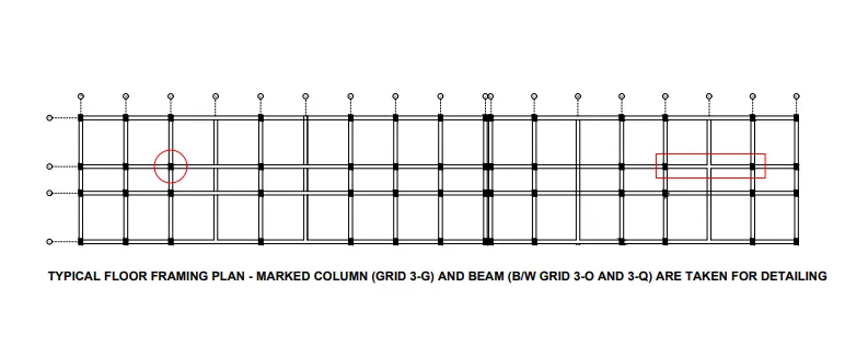
1.TYPICAL FLOOR FRAMING PLAN
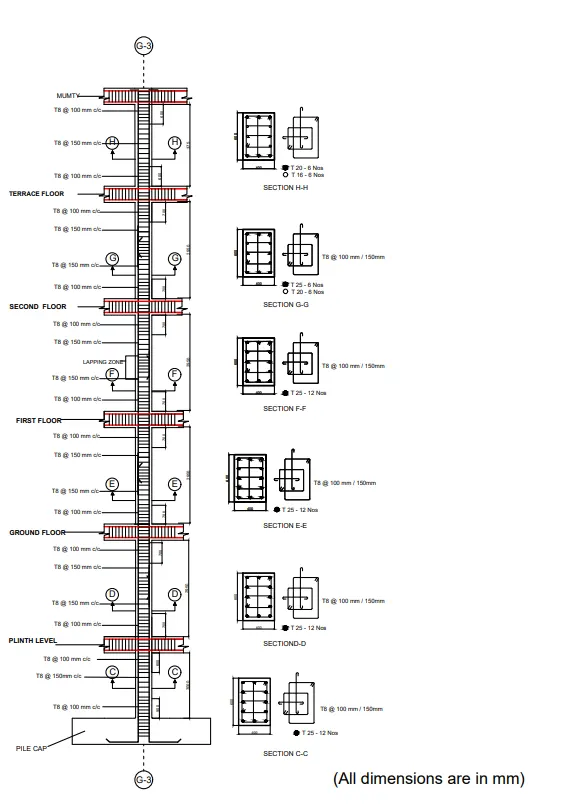
2. TYPICAL COLUMN SECTIONAL DETAIL
3. TYPICAL PILE CAP DETAIL
4. TYPICAL TIE BEAM DETAIL
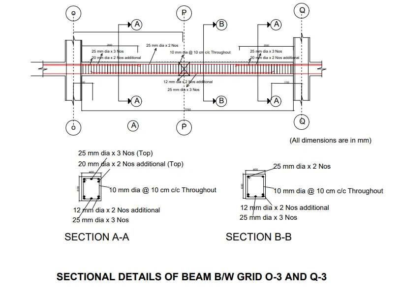
4. TYPICAL ROOF BEAM SECTIONAL DETAILS